Kleinn RAMHDOBA-6450 User manual

RAMHD-734KIT6450
Installation and Operation Manual
Go to Table of Contents PG 1/32 REV: A (08/05/2022)
Table of Contents
1. How to Use this Manual ......................................................................................Error! Bookmark not defined.
2. Safety First ..........................................................................................................................................................3
3. Application Chart................................................................................................................................................3
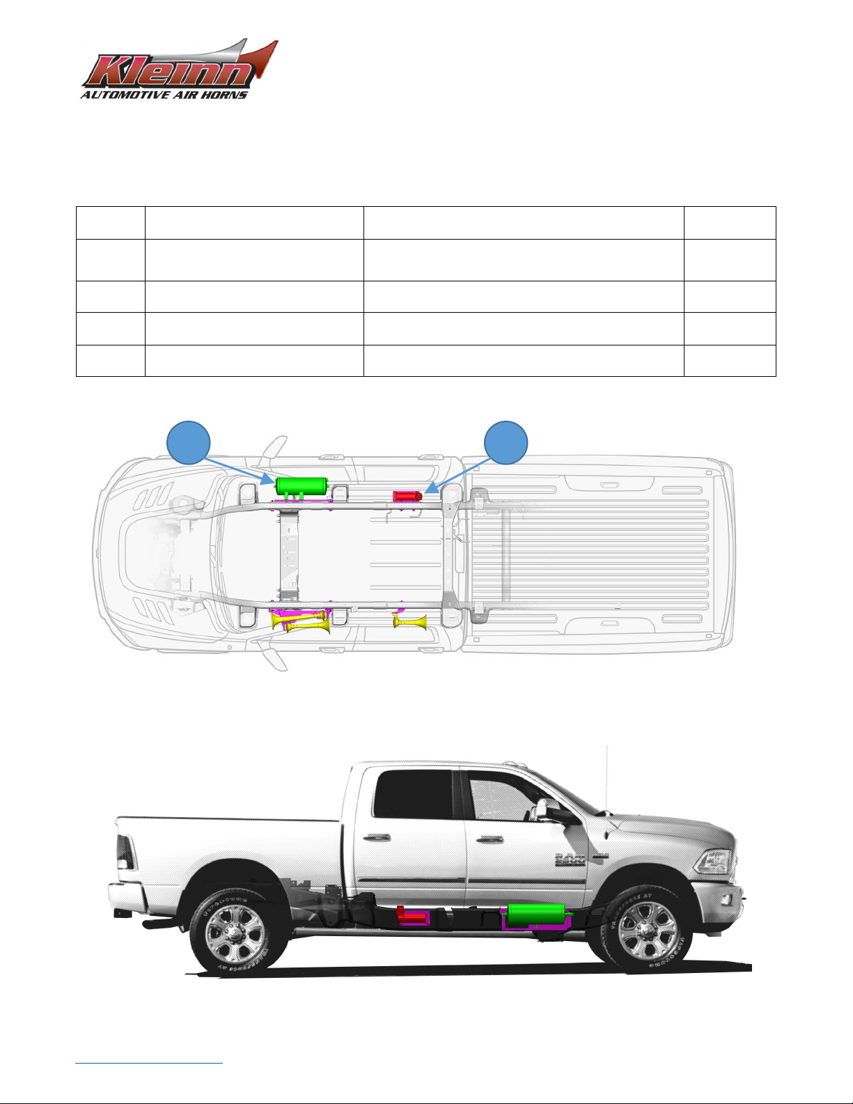
4. Kit Installation Overview ....................................................................................................................................4
4.1. Approximate Installation Time ...................................................................................................................5
5. List of Tools and Supplies ...................................................................................................................................6
5.1. Standard Tool List (Required) .....................................................................................................................6
5.2. Special Tool List (Recommended) ..............................................................................................................6
5.3. Shop Consumables List (Recommended) ...................................................................................................6
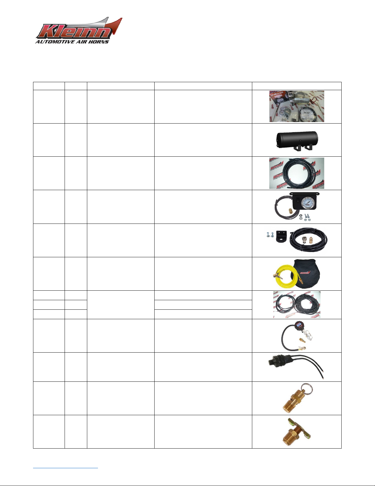
6. Parts List .............................................................................................................................................................7
7. Bench Assembly Steps.........................................................................................Error! Bookmark not defined.
7.1 Unpack and Layout Kit Parts........................................................................Error! Bookmark not defined.
7.2 Disassemble Train Horn Kit..........................................................................Error! Bookmark not defined.
7.3 Mount Medium and Large Horn Drivers to Bracket....................................Error! Bookmark not defined.
7.4 Mount Small Horn Driver to Bracket...........................................................Error! Bookmark not defined.
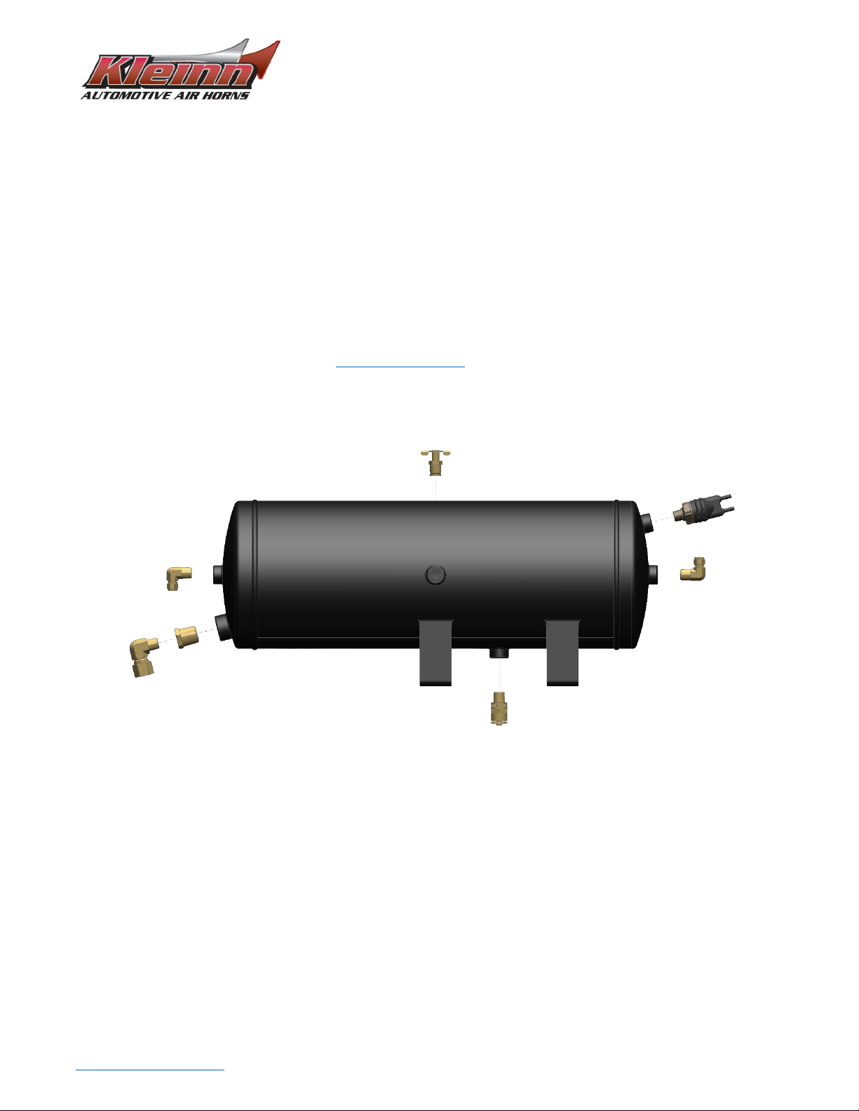
7.5 Mount Air Tank to Bracket ..........................................................................Error! Bookmark not defined.
8. On-Vehicle Mechanical Assembly Steps.......................................................................................................... 12
8.1 Large-Medium Horn Assembly Installation ............................................................................................. 12
8.2 Small Horn Assembly Installation ............................................................................................................ 15
8.3 Air Tank Assembly Installation ................................................................................................................ 18
8.4 Compressor and Bracket Installation ...................................................................................................... 21
9. On Vehicle Air Line Installation ....................................................................................................................... 24
10. On Vehicle Electrical Installation ................................................................................................................. 27
10.1. Disconnect Vehicle Battery(s).............................................................................................................. 27
10.2. Attach Relay to Vehicle........................................................................................................................ 27
10.3. Route Wiring and Install Horn Button ................................................................................................. 27
10.4. Connect Relay to Wiring...................................................................................................................... 28
10.5. Connect Air Horn Solenoid .................................................................................................................. 28
10.6. Reconnect Vehicle Battery(s) .............................................................................................................. 28
11. Initial Testing of Kit...................................................................................................................................... 29
11.1. Test Air Compressor ............................................................................................................................ 29
11.2. Test Train Horns................................................................................................................................... 29

RAMHD-734KIT6450
Installation and Operation Manual
Go to Table of Contents PG 2/32 REV: A (08/05/2022)
11.3. Test Quick Connect Coupler ................................................................................................................ 29
12. General Operation of Kit ............................................................................................................................. 30
12.1. Compressor Operation ........................................................................................................................ 30
12.2. Horn Operation.................................................................................................................................... 30
13. Routine Maintenance .................................................................................................................................. 31
14. Warranty Information ................................................................................................................................. 32

RAMHD-734KIT6450
Installation and Operation Manual
Go to Table of Contents PG 3/32 REV: A (08/05/2022)
1. Safety First
Read manual thoroughly before starting installation of this kit. Verify you have all parts listed and that you
clearly understand this installation procedure. Contact Kleinn technical support for any questions.
Installation of this kit requires moderate mechanical aptitude; seek professional help if you’re not competent
using hand tools in tight uncomfortable spaces, and around possibly rusted and sharp vehicle parts.
Before starting, obtain proper tools required to perform installation correctly, adequate lighting, eye protection,
hearing protection for operating train horns, and hand protection to guard against sharp edges and metal burrs,
which may be present on kit and vehicle parts.
2. Application Chart
RAMHDOBA-6450 is a bolt-on aftermarket product for all DODGE vehicles listed in below chart.
All vehicles listed may require drilling holes for ground wires and installing switches, based on preference of
switch locations and wire grounding points.
MODEL YR
MODEL
DRIVE
ENGINE
BODY
TRIM
2014-2021
RAM 2500
2WD, 4WD
ALL
Crew Cab (short
bed**), Mega Cab
ALL
2014-2021
RAM 3500
2WD, 4WD,
DUALIE
ALL
Crew Cab (short
bed**), Mega Cab
ALL
**Exclusions:
Crew Cab Long Bed, or Regular/Standard Cab frames; these frames will require drilling holes to attach the
following brackets. Contact Kleinn sales for more information.
Compressor Bracket – drill mounting holes for hardware in approximate location shown in instructions
Product Compatibility:
This kit has been designed and tested to be compatible with leading manufacturers of aftermarket truck steps,
such as Amp Research Power Steps ® and all OEM standard and optional steps.

RAMHD-734KIT6450
Installation and Operation Manual
Go to Table of Contents PG 4/32 REV: A (08/05/2022)
3. Kit Installation Overview
RAMHDOBA-6450 consists of the following major components, located on vehicle per following pictures and
chart
Item No. Component Vehicle Location
Install Time
(Approximate)
1. 6355RT
3.0 Gallon Air Tank
Under passenger side front door.
Bolted to outside of frame rail. 2+ Hours
2.
6450RC
150 PSI Waterproof Compressor
Under passenger side rear door.
Bolted to outside of frame rail.
1-2 Hours
*3.
1301
Illuminated Dash Panel Gauge Kit
Installer/Customer Preference 1+ Hours
*4.
1302
Remote Quick Connect Kit
Installer/Customer Preference 1+ Hours
*Not Illustrated
Top View – Ram 2500 Crew Cab Short Bed
Passenger Side View – 2014 Ram 2500 Crew Cab Short Bed
2
1

RAMHD-734KIT6450
Installation and Operation Manual
Go to Table of Contents PG 5/32 REV: A (08/05/2022)
3.1. Approximate Installation Time
RAMHDOBA-6450 is a multi-faceted product consisting of multiple mechanical, electrical, and pneumatic
components.
For a typical home mechanic, or auto enthusiast, a professional installation job with setup and testing of
final product, is estimated to take:
•6+ Hours

RAMHD-734KIT6450
Installation and Operation Manual
Go to Table of Contents PG 6/32 REV: A (08/05/2022)
4. List of Tools and Supplies
4.1. Standard Tool List (Required)
1. Basic mechanic’s 3/8” drive socket sets with extensions
a. Inch Size Sockets (1/4” – 1” Hex)
b. Metric Size Sockets (6mm – 20mm Hex)
2. Basic mechanic’s combination wrenches (box/open-end)
a. Inch Size Wrenches (1/4” – 1” Hex)
b. Metric Size Wrenches (6mm – 20mm Hex)
3. Basic mechanic’s screwdriver set (Philips, Flat Head)
4. Diagonal Cutter/Wire Cutter Pliers
5. Wire Strippers
6. Wire Terminal Crimpers
7. Slip-Joint Pliers
8. Utility Knife, or Utility Razor blade
4.2. Special Tool List (Recommended)
1. 10-100 ft.-lb. torque wrench
2. 50-150 in.-lb. torque wrench
3. Multi-Meter for 12V DC electrical systems, or equivalent
4. 12V DC Test Light, or equivalent
4.3. Shop Consumables List (Recommended)
1. Quality Electrical tape
2. Di-electric grease for electrical connections
3. Heat Shrink tubing for electrical connections
4. Sandpaper, or Wire Brushes for installing ground wires
5. Extra plastic zip ties > 6” long
6. Extra NPT sealant (i.e., Kleinn Air Horn Juice, Teflon tape, etc.)
7. Touch-up paint for frame/chassis
8. Typical cleanup supplies

RAMHD-734KIT6450
Installation and Operation Manual
Go to Table of Contents PG 7/32 REV: A (08/05/2022)
5. Parts List
RAMHDOBA-6450 includes following items:
Item No.
Qty.
Part Number
Description
Picture
1. 1 6450RC 150 PSI Waterproof Compressor with
hardware & remote air supply
2. 1 6355RT 3.0 Gallon Air Tank
3. 12 Ft 25014-1 1/4” Air Tubing
4. 1 1301 Illuminated Dash Panel Gauge Kit
5. 1 1302 Quick Connect Air Coupler Kit, with
relocation bracket
6. 1 INF-1 Tire Inflation Kit w/ bag & fittings
7. 20 Ft
N/A
Loom Pack – 1/4”
8. 10 Ft Loom Pack – 1/8”
9. 5 Ft Loom Pack – 3/8”
10. 1 59830 Digital Tire Inflator w/ Pressure Release
11. 1 2151 1/4” NPT Pressure Switch
110 PSI On, 145 PSI Off
12. 1 52175 1/4” NPT, 175 PSI Safety Valve
13. 1 52835 Drain Valve
1/4” NPT

RAMHD-734KIT6450
Installation and Operation Manual
Go to Table of Contents PG 8/32 REV: A (08/05/2022)
14. 2 51414L 1/4” NPT X 1/4” Compression Fitting
90 Deg Elbow
15. 1 51214R 1/2” NPT to 1/4” NPT Reducer, Female
16. 1 51414F 1/4” NPT F X 1/4” Compression Fitting
17. 1 JUICE Thread Sealant for NPT Fittings
18. 1 N/A 4-Bolt Tank Hardware:
7/16”-14 Bolts, Nuts, and Washers
19. 1 N/A
Hardware Pack:
1/2”-13 Bolts, Nuts and Washers
7/16-14 Nuts and Washers
20. 1 6852 Compressor Wiring Kit, Complete
21. 1 RAMHD_TANK_BRKT-ASSY Air Tank Bracket
22. 1 RAMHD-200 Air Compressor Bracket
23. 3 RAMHD_WASHER Washer for Frame Slots
24. 1 RAMHD-201
(for 2019+ RAMHD) Compressor Bracket Bolt Tie

RAMHD-734KIT6450
Installation and Operation Manual
Go to Table of Contents PG 9/32 REV: A (08/05/2022)
6. Bench Assembly Steps
Complete following steps off vehicle to facilitate final installation.
6.1. Component Layout
Unpackage RAMHDOBA-6450 and verify all parts are included per above Parts List. Contact Kleinn support if any
questions arise.
6.2. Air Tank Fittings
1. Attach and tighten air fittings to tank, per below illustrations.
a. Apply two small drops of Kleinn Air Horn Juice to each male pipe thread.
b. Hand-tighten each fitting, then further tighten each 1/4-1/2 turn using proper sized combination
wrench (or equivalent); adjust as necessary to match fitting orientation shown.

RAMHD-734KIT6450
Installation and Operation Manual
Go to Table of Contents PG 10/32 REV: A (08/05/2022)
2. Attach air tank to bracket, per below illustration.
a. Use 4 Bolt Tank Hardware kit
i. Assemble fasteners clean and dry; tank should not move freely, but can be repositioned
with some hand force.
ii. Final tightening will be completed on vehicle.

RAMHD-734KIT6450
Installation and Operation Manual
Go to Table of Contents PG 12/32 REV: A (08/05/2022)
6. On-Vehicle Mechanical Assembly Steps
Complete following steps on vehicle.
Raise vehicle off ground using appropriate vehicle lift, ramps, or jack stands.
DANGER: Installation requires being underneath vehicle and applying forces to vehicle chassis. Follow all
recommended safety preCAUTIONs for raising vehicle; consult vehicle owner’s manual.
8.1 Large-Medium Horn Assembly Installation
1. Attach Large-Medium Horn bracket assembly onto vehicle chassis, per below illustration.
a. Use RAMHD Hardware kit.
i. Finger tighten fasteners only, but ensure bracket is sitting entirely flush on chassis.
b. Install Medium trumpet into open driver and tighten firmly.
Crew Cab and Mega Cab Orientation

RAMHD-734KIT6450
Installation and Operation Manual
Go to Table of Contents PG 13/32 REV: A (08/05/2022)
Crew Cab and Mega Cab Orientation
2. Position bracket properly and tighten fasteners, per below illustration.
a. Move bracket up-down, and fore-aft, as necessary to ensure adequate clearance between all
trumpets and underbody
i. Large Horn Trumpet must have minimum 1/4” (i.e., thickness of Bic Pen) clearance
between underbody floor brace.
ii. Horns can also be repositioned on bracket slots.
b. Hold bracket in correct position and tighten mounting fasteners firmly
c. Tighten horn mounting fasteners to bracket firmly

RAMHD-734KIT6450
Installation and Operation Manual
Go to Table of Contents PG 15/32 REV: A (08/05/2022)
8.2 Small Horn Assembly Installation
1. Attach Small Horn bracket assembly onto vehicle chassis, per below illustration.
a. Use RAMHD Hardware kit.
i. Finger tighten fasteners only, but ensure bracket is sitting entirely flush on chassis.
b. Install Small trumpet into open driver and tighten firmly.
Crew Cab Orientation

RAMHD-734KIT6450
Installation and Operation Manual
Go to Table of Contents PG 17/32 REV: A (08/05/2022)
Mega Cab Orientation
2. Position bracket properly and tighten fasteners, per below illustration.
a. Move bracket up-down, and fore-aft, as necessary to ensure adequate clearance between
trumpet and underbody
i. Horn can also be repositioned on bracket slots.
b. Hold bracket in correct position and tighten mounting fasteners firmly
c. Tighten horn mounting fasteners to bracket firmly
Crew Cab Orientation

RAMHD-734KIT6450
Installation and Operation Manual
Go to Table of Contents PG 18/32 REV: A (08/05/2022)
8.3 Air Tank Assembly Installation
WARNING:Installing air tank onto vehicle chassis requires hands to be near exhaust system; make sure
vehicle exhaust is cool enough to touch before installation.
1. Attach Air Tank assembly onto vehicle chassis, per below illustration.
a. Use RAMHD Hardware kit.
i. Ensure bracket is sitting entirely flush on chassis and finger tighten fasteners
Crew Cab and Mega Cab Orientation

RAMHD-734KIT6450
Installation and Operation Manual
Go to Table of Contents PG 19/32 REV: A (08/05/2022)
Crew Cab and Mega Cab Orientation
2. Position bracket properly and tighten fasteners, per below illustrations.
b. Move bracket up/down, and fore/aft, as necessary to ensure adequate clearance around tank
i. Air Tank must have minimum 1/4” clearance between underbody and rocker panels
ii. Reposition Tank up/down on bracket slots, if necessary
c. Hold bracket in correct position and tighten mounting fasteners firmly
d. Tighten Tank mounting fasteners to bracket firmly
Other manuals for RAMHDOBA-6450
1
Table of contents
Other Kleinn Horn manuals