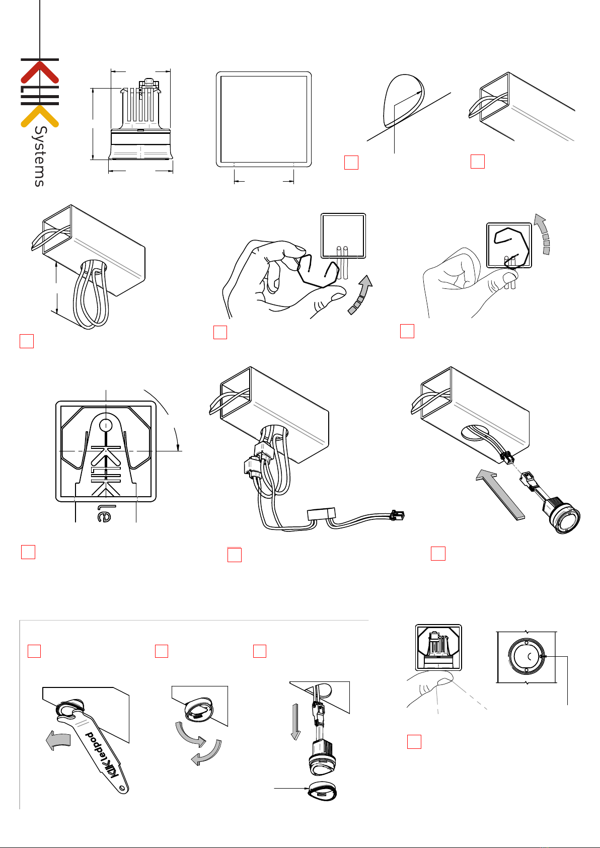
Feed wires through tube. Be careful
not to sever wires whilst feed past
pre-installed retaining clasps.
Pull a loop of wire through as shown.
Rotate retaining clasps in as shown. Apply pressure as shown to deform
clasp into place in a circular motion.
Fit clasp into place until the clamping
ends are equally centred over the hole.
Use tool to centre clasp until equally
pressure can be felt and inspect by eye.
LEDPOD 40SQ Installation Instructions
Patent pending
90°
www.kliksystems.com.au - info@kliksystems.com.au
60mm
Install Scotchlok connectors to the
18-16 AWG (0.75-1.5) red and black
wires. Connect the corresponding colour
wires of the Driver to the Scotchloks and
assure the clamp is secured. Max wire
insulation 3.5mm OD
Push LEDPOD in until it snaps into place
and the outer surface is flush with the outer
surface of the tube.
Prod the rim of the clear silicone IP Seal to
provide a tighter fit.
CAREFULLY feed the Scotchloks to
the left of the clasp and the driver to
the right with the driver connector
hanging out.
Proceed to connect the LEDPOD
The notch indicates
the direction of the light,
Asymmetrical LEDPods
Light
direction
LEDPOD Removal Steps
Insert removal tool into the
2mm holes in the LEDPOD
With firm pressure, rotate
the LEDPod 90° to release
the luminaire from the clasp.
Carefully peel back
the IP silicone seal
one side at a time.
Carefully remove the LEDPOD
from the clasp, ensuring not to
damage or disconnect wires in
the process.
NEGATIVE [ - ]: Black
POSITIVE [ + ]: Red
32865-A
1
234
567
8
12 3
30
26.9
O
24.8
O
25 ±0.2
O
Be sure to re-attach
the silicone seal ready
for reinsertion.
Ensure pre-drilled holes are deburred
and excess swarf is removed.
LEDpod 40 Square Installation Instructions
25 ±0.2
O
O
26
24.7
O
30
90°
www.kliksystems.com.au - info@kliksystems.com.au
60mm
Push LEDPOD in until it snaps into place
and the outer surface is flush with the
outer surface of the tube.
Prod the rim of the clear siliconeIP Seal to
provide a tighter fit.
The notch indicates
the direction of the light,
Asymmetrical LEDPods
Light
direction
LEDPOD Removal Steps
Insert removal tool into the
2mm holes in the LEDPOD
With firm pressure, rotate
the LEDPod 90°
Carefully peel back
the IP silicone seal
one side at a time.
Carefully remove the LEDPOD
from the clasp, ensuring not to
damage or disconnect wires in
the process.
Be sure to re-attach
the silicone seal ready
for reinsertion.
NEGATIVE [ - ]: Black
POSITIVE [ + ]: Red
9
1 2 3
Thru.
wire
LEDPOD 40 Installation Instructions
R
Pull a loop of wire through hole. Rotate retaining clasps in as shown. Avoid
tangling or severing through wire.
3 4 5
Apply pressure as shown to deform clasp into place in
a circular motion. Avoid damaging the surface of tube
and tangling or severing through wire.
PAGE 1 OF 2
Install Scotchlok connectors to the (0.75-1.5sq) red
and black wires. Connect the corresponding colour
wires of the Driver to the Scotchloks and assure the
clamp is secured.
CAREFULLY feed the Scotchloks to the left
of the clasp and the driver to the right with the
driver connector hanging out. Ensure wires
are clear from where the LEDPOD is to fit.
Proceed to connect the LEDPOD
6 7 8
Fit clasp into place until the clamping
ends are equally centred over the hole.
Use the tool to centre the clasp until
equal pressure can be felt and inspect
by eye.
Feed through appropriate
wires (0.75-1.5mm²).
2
Make sure drilled holes are
deburred and excess swarf
is removed from railing.
1
32863-C
Feed wires through tube. Be careful
not to sever wires whilst feed past
pre-installed retaining clasps.
Pull a loop of wire through as shown.
Rotate retaining clasps in as shown. Apply pressure as shown to deform
clasp into place in a circular motion.
Fit clasp into place until the clamping
ends are equally centred over the hole.
Use tool to centre clasp until equally
pressure can be felt and inspect by eye.
LEDPOD 40SQ Installation Instructions
Patent pending
90°
www.kliksystems.com.au - info@kliksystems.com.au
60mm
Install Scotchlok connectors to the
18-16 AWG (0.75-1.5) red and black
wires. Connect the corresponding colour
wires of the Driver to the Scotchloks and
assure the clamp is secured. Max wire
insulation 3.5mm OD
Push LEDPOD in until it snaps into place
and the outer surface is flush with the outer
surface of the tube.
Prod the rim of the clear silicone IP Seal to
provide a tighter fit.
CAREFULLY feed the Scotchloks to
the left of the clasp and the driver to
the right with the driver connector
hanging out.
Proceed to connect the LEDPOD
The notch indicates
the direction of the light,
Asymmetrical LEDPods
Light
direction
LEDPOD Removal Steps
Insert removal tool into the
2mm holes in the LEDPOD
With firm pressure, rotate
the LEDPod 90° to release
the luminaire from the clasp.
Carefully peel back
the IP silicone seal
one side at a time.
Carefully remove the LEDPOD
from the clasp, ensuring not to
damage or disconnect wires in
the process.
NEGATIVE [ - ]: Black
POSITIVE [ + ]: Red
32865-A
1
234
567
8
12 3
30
26.9
O
24.8
O
25 ±0.2
O
Be sure to re-attach
the silicone seal ready
for reinsertion.
Ensure pre-drilled holes are deburred
and excess swarf is removed.
25 ±0.2
O
O
26
24.7
O
30
90°
www.kliksystems.com.au - info@kliksystems.com.au
60mm
Push LEDPOD in until it snaps into place
and the outer surface is flush with the
outer surface of the tube.
Prod the rim of the clear siliconeIP Seal to
provide a tighter fit.
The notch indicates
the direction of the light,
Asymmetrical LEDPods
Light
direction
LEDPOD Removal Steps
Insert removal tool into the
2mm holes in the LEDPOD
With firm pressure, rotate
the LEDPod 90°
Carefully peel back
the IP silicone seal
one side at a time.
Carefully remove the LEDPOD
from the clasp, ensuring not to
damage or disconnect wires in
the process.
Be sure to re-attach
the silicone seal ready
for reinsertion.
NEGATIVE [ - ]: Black
POSITIVE [ + ]: Red
9
1 2 3
Thru.
wire
LEDPOD 40 Installation Instructions
R
Pull a loop of wire through hole. Rotate retaining clasps in as shown. Avoid
tangling or severing through wire.
3 4 5
Apply pressure as shown to deform clasp into place in
a circular motion. Avoid damaging the surface of tube
and tangling or severing through wire.
PAGE 1 OF 2
Install Scotchlok connectors to the (0.75-1.5sq) red
and black wires. Connect the corresponding colour
wires of the Driver to the Scotchloks and assure the
clamp is secured.
CAREFULLY feed the Scotchloks to the left
of the clasp and the driver to the right with the
driver connector hanging out. Ensure wires
are clear from where the LEDPOD is to fit.
Proceed to connect the LEDPOD
6 7 8
Fit clasp into place until the clamping
ends are equally centred over the hole.
Use the tool to centre the clasp until
equal pressure can be felt and inspect
by eye.
Feed through appropriate
wires (0.75-1.5mm²).
2
Make sure drilled holes are
deburred and excess swarf
is removed from railing.
1
32863-C
9
Feed wires through tube. Be careful
not to sever wires whilst feed past
pre-installed retaining clasps.
Pull a loop of wire through as shown.
Rotate retaining clasps in as shown. Apply pressure as shown to deform
clasp into place in a circular motion.
Fit clasp into place until the clamping
ends are equally centred over the hole.
Use tool to centre clasp until equally
pressure can be felt and inspect by eye.
LEDPOD 40SQ Installation Instructions
Patent pending
90°
www.kliksystems.com.au - info@kliksystems.com.au
60mm
Install Scotchlok connectors to the
18-16 AWG (0.75-1.5) red and black
wires. Connect the corresponding colour
wires of the Driver to the Scotchloks and
assure the clamp is secured. Max wire
insulation 3.5mm OD
Push LEDPOD in until it snaps into place
and the outer surface is flush with the outer
surface of the tube.
Prod the rim of the clear silicone IP Seal to
provide a tighter fit.
CAREFULLY feed the Scotchloks to
the left of the clasp and the driver to
the right with the driver connector
hanging out.
Proceed to connect the LEDPOD
The notch indicates
the direction of the light,
Asymmetrical LEDPods
Light
direction
LEDPOD Removal Steps
Insert removal tool into the
2mm holes in the LEDPOD
With firm pressure, rotate
the LEDPod 90° to release
the luminaire from the clasp.
Carefully peel back
the IP silicone seal
one side at a time.
Carefully remove the LEDPOD
from the clasp, ensuring not to
damage or disconnect wires in
the process.
NEGATIVE [ - ]: Black
POSITIVE [ + ]: Red
32865-A
1
234
567
8
12 3
30
26.9
O
24.8
O
25 ±0.2
O
Be sure to re-attach
the silicone seal ready
for reinsertion.
Ensure pre-drilled holes are deburred
and excess swarf is removed.
25 ±0.2
O
O
26
24.5
O
34
LEDPOD 50 Installation Instructions
NEGATIVE [ - ]: Black
POSITIVE [ + ]: Red
90°
Push LEDPOD in until it snaps into place
and the outer surface is flush with the outer
surface of the tube.
Prod the rim of the clear silicone IP Seal to
provide a tighter fit.
The notch indicates
the direction of the light,
Asymmetrical LEDPods
Light
direction
60mm
Insert removal tool into the
2mm holes in the LEDPOD
With firm pressure, rotate
the LEDPod 90°
Carefully peel back
the IP silicone seal
one side at a time.
Carefully remove the LEDPOD
from the clasp, ensuring not to
damage or disconnect wires in
the process.
Be sure to re-attach
the silicone seal ready
for reinsertion.
www.kliksystems.com.au - info@kliksystems.com.au
9
1 2 3
LEDPOD Removal Steps
Thru.
wire
R
PAGE 1 OF 2
Pull a loop of wire through hole. Rotate retaining clasps in as shown. Avoid
tangling or severing through wire.
3 4 5
Apply pressure as shown to deform clasp into place in
a circular motion. Avoid damaging the surface of tube
and tangling or severing through wire.
Install Scotchlok connectors to the (0.75-1.5sq) red
and black wires. Connect the corresponding colour
wires of the Driver to the Scotchloks and assure the
clamp is secured.
CAREFULLY feed the Scotchloks to the left
of the clasp and the driver to the right with the
driver connector hanging out. Ensure wires
are clear from where the LEDPOD is to fit.
Proceed to connect the LEDPOD
6 7 8
Fit clasp into place until the clamping
ends are equally centred over the hole.
Use the tool to centre the clasp until
equal pressure can be felt and inspect
by eye.
Feed through appropriate
wires (0.75-1.5mm²).
2
Make sure drilled holes are
deburred and excess swarf
is removed from railing.
1
32864-C


