KLINGE TCR-104-07 Guide

UNCONTROLLED WHEN PRINTED K35-TCR104-07
REV. E, JUNE 2023
MODEL TCR-104-07: Standard
MODEL TCR-104-08: Remote Electrical Box
MODEL TCR-104-09: With Alarm System &
Version 2 Recorder
MODEL TCR-104-10: Standard W/ Drain – R-404A
MODEL TCR-104-20: Standard W/ Drain – R-452A
CLOSED GLYCOL SYSTEM
(Options)
Heat and Microprocessor Data logging
TANK CONTAINER REFRIGERATION UNIT
OPERATION, SERVICE AND PARTS MANUAL
Address: 4075 East Market Street York, PA 17402-5100 USA
Telephone: 717-840-4500 Telefax: 717-840-4501
www.klingecorp.com
Manufactured by KLINGE CORPORATION

UNCONTROLLED WHEN PRINTED K35-TCR104-07
REV. E, JUNE 2023
2

UNCONTROLLED WHEN PRINTED K35-TCR104-07
REV. E, JUNE 2023
3
REVISION RECORD
Rev Description Date Approved
A Numerous changes to content, and format
to bring to current manual standards. 03/26/2018 BES
B Add R-452A as a refrigerant option 3/12/2020 BES
C Updated Glycol Pump Overload range pg 16 10/20/2022 BES
D Updated Section 8.2A, Item 16 3/7/2023 DBG
E Updated receiver part # 11 Section 8.1B 6/14/2023 BES

UNCONTROLLED WHEN PRINTED K35-TCR104-07
REV. E, JUNE 2023
4
Service Request
Requests for Service should be directed to the Klinge Service Team. The below link should be used to
place all requests for service and will afford the quickest response time.
https://klingecorp.com/request-service/
This form will help us determine model and age of the equipment, location, basic details about the
issue, who to contact and how to best handle the issues with the equipment. A service ticket number
will be provided in a response email once the form is received and processed. If the equipment is out
of warranty, charges may apply for extensive technical support.
Spare Parts Request
Requests for Spare Parts should be directed to our Parts Department via email at
[email protected].Please have available at the time of the request the Serial Number of the
equipment to ensure that the proper part is provided.
Use of this Manual
The use of this manual is intended for the safe operation of the equipment described. It is therefore
reasoned that persons who have the occasion to use this manual have a knowledge of mechanical and
electrical systems and components addressed by its' contents. However, efforts have been made to
enable persons less familiar with these systems to use this manual.
The equipment may be installed in a number of configurations. Each may have optional items and
differing external details provided by third parties. The specific electrical circuit and pipe diagram are
posted on the unit as decals.
Most external and internal pipework parts are standard commercially available pipe fittings and not
covered here. For external pipe fitting, replace like for like, taking care to replace stainless steel with
stainless steel.
Suggestions as to improvement in content and format are welcome and should be addressed to
[email protected].Corrections and improvements will be included on dated revisions –
the latest of which will be available upon request.

UNCONTROLLED WHEN PRINTED K35-TCR104-07
REV. E, JUNE 2023
5
Table of Contents
Service Request...................................................................................................................................................4
Spare Parts Request.............................................................................................................................................4
Use of this Manual..............................................................................................................................................4
1.0 GENERAL DESCRIPTION............................................................................................................................7
1.1 Compressor..................................................................................................................................................7
1.2 Chiller..........................................................................................................................................................7
1.3 Glycol Components & System.....................................................................................................................7
1.4 Refrigeration System & Components..........................................................................................................8
1.5 Heaters (if equipped)....................................................................................................................................9
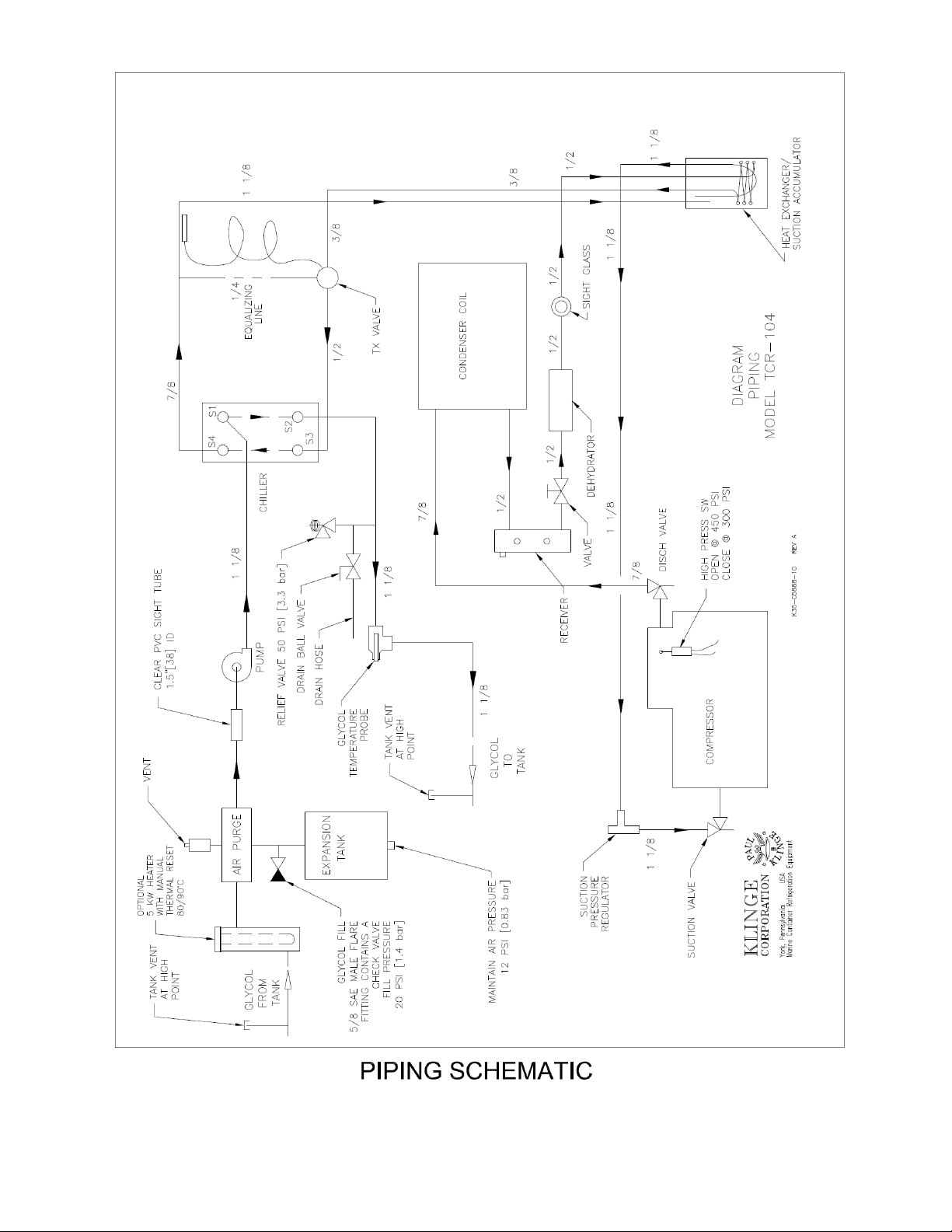
1.6 Piping Schematic.......................................................................................................................................10
2.0 OPERATION.................................................................................................................................................11
2.1 Pre-starting Check......................................................................................................................................11
2.2 Starting Check............................................................................................................................................11
2.3 Running Unit..............................................................................................................................................11
3.0 ELECTRICAL FUNCTIONS.......................................................................................................................15
3.1 General Information (Refer to Electrical Schematic)................................................................................15
3.2 Electrical Box.............................................................................................................................................15
3.3 Electrical Schematic...................................................................................................................................17
4.0 MICROPROCESSOR THERMOSTAT........................................................................................................19
4.1 General Information...................................................................................................................................19
4.2 Display Panel.............................................................................................................................................19
4.3 Temperature Sensors..................................................................................................................................21
4.4 Microprocessor Thermostat and Data logger.............................................................................................21
4.5 Microprocessor Control Sequence/ Functionality......................................................................................22
5.0 MAINTENANCE AND SERVICE INSTRUCTION...................................................................................27
5.1 General.......................................................................................................................................................27
5.2 Safety.........................................................................................................................................................27
5.3 Checking Refrigerant Charge.....................................................................................................................28
5.4 Procedure for adding refrigerant................................................................................................................28
5.5 Non-condensable gases..............................................................................................................................29
5.6 Opening the System...................................................................................................................................29
5.7 Testing for Leaks.......................................................................................................................................29
5.8 Evacuating the System...............................................................................................................................30
5.9 Glycol System............................................................................................................................................30
5.10 PTI Form..................................................................................................................................................37

UNCONTROLLED WHEN PRINTED K35-TCR104-07
REV. E, JUNE 2023
6
6.0 SERVICING COMPONENTS......................................................................................................................38
6.1 Compressor................................................................................................................................................38
6.2 Condenser Fan Motor.................................................................................................................................40
6.3 Condenser Fan...........................................................................................................................................41
6.4 Filter Drier Replacement............................................................................................................................41
6.5 High Pressure Switch.................................................................................................................................41
6.6 Thermal Expansion Valve..........................................................................................................................42
7.0 TROUBLE SHOOTING................................................................................................................................45
7.1 General Information...................................................................................................................................45
7.2 Service Components..................................................................................................................................45
7.3 Microprocessor Thermostat.......................................................................................................................45
7.4 Trouble Shooting Chart..............................................................................................................................46
8.0 SERVICE PARTS.........................................................................................................................................51
Suggested Spare Parts.......................................................................................................................................80

UNCONTROLLED WHEN PRINTED K35-TCR104-07
REV. E, JUNE 2023
7
1.0 GENERAL DESCRIPTION
This unit is specially designed for cooling heat transfer fluid, which is used to control the temperature
of tank containers.
The machine is designed for uses in combination with ethylene glycol, propylene glycol, or synthetic
oils where different cargoes dictate a different cooling medium. Ethylene glycol is commonly used
with most chemical cargoes. Propylene glycol is used with foods and synthetic oils are used for high
and low temperature cargoes. With due consideration for non-metallic pipe connections a mixture of
diphenylethane and alkylated aromatics, can be used for very low temperatures if required.
The basic equipment of the standard configuration of the TCR-104 includes the following:
a discus compressor using R-404A or R-452A,
a plate chiller section,
a circulating pump,
provision for an optional 5kW heater (not fitted here)
A detailed description of the system follows.
An adjustable thermostat and two probes monitor the temperature of the cargo in the tank and the
glycol system. The thermostat is then linked in the electromechanical system to control operation of
the pump, compressor, suction-throttling valve, and fan.
The connection to the tank’s circulating system is made with the necessary components, built into the
tank and supplied by the tank builder.
1.1 Compressor
Compressor is a Copeland discus compressor, specifically designed for transport operation. The
compressor is supplied with a deep oil sump to provide larger oil capacity. Protection from salt
atmosphere is provided by a double coating of Pit guard paint. The compressor, which has been
available since 1988, is rugged and has many new high-tech features. The shaft is impregnated with
Teflon to provide lubrication should the compressor lose lubrication for a short period of time, the
valve seats are made of a permeable material which permits the compressor to obtain optimum seating
after the first 72 hours of operation.
1.2 Chiller
The chiller is a solid, brazed plate unit construction producing a very compact rugged heat exchanger.
This stack plate type construction, using the very latest in continuous vacuum brazing technology, is
more compact, efficient, reliable, and maintenance-free than ordinary units.
1.3 Glycol Components & System
The glycol system is a closed system. The glycol is not exposed to the air. This is accomplished by
using a buffer tank with a bladder to allow for the expansion and contraction of the glycol as
temperatures change. No air can get into the system, as would be the case with a naturally aspirated
expansion tank.

UNCONTROLLED WHEN PRINTED K35-TCR104-07
REV. E, JUNE 2023
8
Air in the system would promote corrosion and could get trapped. This could cause noisy, inefficient
operation and energy waste. The result would be loss of pump performance and corrosion of
equipment.
The bladder in the expansion tank has air or nitrogen on one side and system glycol on the other. The
gas is pressurized to 0.8 Bar (12 psig). This maintains a system pressure of 0.8 Bar (12 psi).
The system has a fill valve set at 0.8 Bar (12 psi). This allows the system to be filled to exactly 0.8
Bar (12 psi) glycol pressure automatically. Each glycol system is equipped with an air purger and
float vent which automatically purge the air out of the system and expel it into the atmosphere. This
removes any air, which may be in the glycol when the system is filled. The system also has a safety
pressure relief valve, which is set at 3.5 Bar (50 psi).
The glycol pump is powered by a 1½ H.P. TEFC motor at 3450 RPM. The motor is slightly over
sized. At no time will the pump load exceed 1½ H.P.
1.3.1 Cleanliness of the Glycol System
New cooling systems are typically coated with oil, grease, or protective film during fabrication.
Welding by products, flux and scale that would not normally cause a problem with a steam system can
cause a problem with the glycol heat exchanger – the chiller.
Dirt will migrate to the chiller (a plate type heat exchanger) and may block the small gaps between
each plate. Because of this, thoroughly cleaning the new system is important.
A solution of 1 to 2% trisodium phosphate can be used with water for flushing the cooling pipes.
The system volume can be calculated at this stage by metering in the cleaning material.
This cleaning should be completed prior to connecting the TCR-104 unit.
We suggest that a gauze or muslin cloth be used to filter and observe the output of the cleaning
medium. Use the lack of returning dirt as a guide to cleanliness.
NOTE: As it is an inherently closed loop system, the unit purposely does not have the restriction of an
in-line filter in the glycol line and depends on the system being cleaned at the initial charge filling.
1.4 Refrigeration System & Components
In addition to the compressor and chiller the refrigeration system includes thermal expansion valve
(TXV), drier, sight glass, condenser coil, receiver, pressure switch and heat exchanger/suction
accumulator.
The suction pressure-regulating valve prevents the suction pressure from increasing above a pre-
determined value. This prevents the compressor motor and engine generator set from being
overloaded at pull down conditions on high ambient days.
The heat exchanger/suction accumulator prevents liquid slugging of the compressor and uses the cold
suction gas to sub-cool the liquid line.

UNCONTROLLED WHEN PRINTED K35-TCR104-07
REV. E, JUNE 2023
9
The receiver is equipped with (2) sight glasses. The bottom sight glass should be filled and the ball
floating during normal operation.
1.5 Heaters (if equipped)
The immersion heaters are 3 phase heaters for operation on 480-volt 3 phase power. At 480 Volts, the
power is 5kW. These heaters must be submerged at all times when in operation.
There is a safety thermal release permanently set to 110°C. If tripped this device opens all 3 legs of
the heater assembly.

UNCONTROLLED WHEN PRINTED K35-TCR104-07
REV. E, JUNE 2023
10
1.6 Piping Schematic

UNCONTROLLED WHEN PRINTED K35-TCR104-07
REV. E, JUNE 2023
11
2.0 OPERATION
2.1 Pre-starting Check
The following inspection should be made before the container is loaded as part of a pre-trip inspection.
All electrical power to the unit should be disconnected before inspection.
1. Visually check unit for physical damage.
2. Visually check major hold-down bolts, door latches.
3. Visually confirm presence of glycol in clear sight tube between pump and expansion tank.
4. Thoroughly check all refrigerant and glycol joints and connections for traces of oil or glycol,
which could be caused by a small refrigerant or glycol leak.
5. Open control box cover and check that all electric components are secure and that terminal
connections are tight.
6. Check gasket on control box and make sure that the cover is safely closed.
7. Check cleanliness of condenser coil and clean if necessary.
2.2 Starting Check
1. Connect MAIN POWER PLUG into receptacle to supply power to unit.
2. Be sure CB1, CB2 and CB3 breakers are in the ON position.
Initiate Function Test — Hold test switch down and simultaneously switch unit ON-OFF switch to the
ON position. Unit will now function test automatically.
After completion of function test (approx. one minute), check amperage of the compressor motor,
condenser fan motor and glycol pump. At the same time, check all indicating lights and direction of
rotation of condenser fan and glycol pump.
Adjust temperature set point to 0°C (32°F). Check refrigerant level in receiver sight-glass after
approx. 15 minutes of continuous running with system fully loaded.
2.3 Running Unit
2.3.1 Phase Selection
The phase sensor monitors the three- phase system for phase sequence and unbalance due to phase
angle and phase voltage deviations such as blown fuse or a bad connection.
When the unit's ON/OFF switch is put in ON position, power feeds into the phase sensor's changing
device. When the phase sensor is energized, it scans the phasing of the input power and will allow
either PC1 or PC2 to become energized to ensure the correct rotation of the fans.
2.3.2 Temperature Controlling (two probe system, thermostat program K35 00858)
There are two temperature control settings; the cargo set point and the safety limit temperature to
prevent local “under cooling” (or “over heating”).
It is inherent in all conduction heating and cooling that the heat transfer medium must hotter or colder
than the cargo being controlled. With many cargoes, this is not a problem but with certain cargoes, the

UNCONTROLLED WHEN PRINTED K35-TCR104-07
REV. E, JUNE 2023
12
storage temperature is optimally very close to the temperature that freezing, crystallization,
caramelizing, distillation/separation, and such non-reversible physical changes may occur. Local
overcooling or overheating of the cargo at the point at which the glycol first comes in contact with the
tank may be a problem with these liquids.
To allow the cargo to be set as near the optimum temperature as possible, the circulating glycol
temperature as well as the cargo temperature is part of the control system.
Both temperature control settings are determined by the setting of the touch pad control panel. The
sequence of events or cycles of the unit are governed by the controller in conjunction with the cargo
and supply glycol temperature probes and the temperature control settings selected on the touch pad
panel.
There are two possible control configurations depending on the cargo:
1) For normal for cargoes that are not sensitive to local “under-cooling” (or “over heating”) - the
safety limit temperature can be set at a high value, effectively taking this feature out of the operation.
Cargo probe temperature 0.5°C (0.9°F) above set point will initiate cooling. The compressor
will operate; the glycol pump will run; and the condenser fan will operate to draw air over the air-
cooled condenser coil. At the set point the compressor and condenser fan motor will cycle off. The
glycol pump will continue to run and circulate glycol. Cargo probe temperature 0.5°C (0.9°F) below
set point will initiate heating. The glycol pump will run, and the heater will energize. At the set point
the heater will cycle off. The glycol pump will continue to run and circulate glycol.
2) For cargoes that are sensitive to local “under-cooling” (or “over heating”) - the safety limit
temperature must be set at a lower value, the minimum setting is 2.2°C (4°F). The lower the setting
the more sensitive the unit will be to local “under-cooling” (or “over heating”).
With the safety limit set at a low value the above sequence will operate. However, if the glycol
probe temperature exceeds the safety limit setting, the heating or cooling function will terminate until
the circulating glycol temperature as determined by the glycol probe returns within the safety limit
setting. The pump will continue to circulate the glycol.
Example: If the unit is cooling with set point at 15°C and the safety limit setting at 5°C,
the safety feature will terminate cooling if the glycol probe senses a supply
glycol temperature of 10°C or less (15 – 5 = 10).
If the unit is heating with set point at 15°C and the safety limit setting at 5°C,
the safety feature will terminate heating if the glycol probe senses a supply
glycol temperature of 20°C or more (15 + 5 = 20).
This is illustrated in the accompanying limit chart.
The temperature indicated by the LED touch pad is the cargo probe temperature. The probe is
located in a bulb well in the container. The end of the probe should be against the bottom of the
tank bulb well and the well filled with a conductive material like graphite grease.
2.3.3 Function Test (Use labels on right side of thermostat)
To initiate a function test, hold test switch down and switch unit ON/OFF switch to ON.

UNCONTROLLED WHEN PRINTED K35-TCR104-07
REV. E, JUNE 2023
13
All indicator LEDs will flash, and the unit will then proceed through the following steps. Each step
will last approximately 8 seconds.
phase sensor and pump will come ON
condenser fan ON
compressor ON
heater LED will come on (may be seen through the label if not heater equipped)
Cargo probe LED will come on and the probe is tested for an open or closed circuit
Glycol probe LED will come on and the probe is tested for an open or closed circuit
the 8th LED will come on, but is not used in this application
If there is a problem at any of the steps the LED associated with that step will flash.
On successfully completion of the test, the unit will return to normal operation.
2.3.4 Glycol Pump Heat
The energy of the pumping action is transferred to the glycol in the form of heat. Therefore, if for
some reason the unit is not cooling it is best to turn the system off to avoid heating up the product in
the tank from the heat from the pump.

UNCONTROLLED WHEN PRINTED K35-TCR104-07
REV. E, JUNE 2023
14

UNCONTROLLED WHEN PRINTED K35-TCR104-07
REV. E, JUNE 2023
15
3.0 ELECTRICAL FUNCTIONS
3.1 General Information (Refer to Electrical Schematic)
When high voltage power is being fed to the unit and CB1 is in the ON position, power will pass along
L1, L2 and L3 to the compressor contactor, transformer, phase sensor and phase contactors. When the
phase sensor is energized, PC1 or PC2 will be energized and allow power to the condenser fan
contactor and glycol pump.
From this point the microprocessor thermostat will maintain the temperature. The microprocessor
thermostat compares the temperature of the probe with the set point and calls for cooling when it is
required.
All wires have numbers printed at both ends.
3.2 Electrical Box
3.2.1 Circuit Breaker
1. Circuit breaker. (CB1)
This 16 Amp circuit breaker is a 3-phase device. It is reset manually and protects the entire unit
against overload. The breaker may be used as an OFF/ON switch.
2. Circuit breaker. (CB2)
A 2 pole, 4 Amp circuit breaker protects the 24-volt control circuit in case of possible short circuits.
3. Circuit breaker. (CB3)
A 2 pole 4 Amp circuit breaker that protects the 12-volt control circuit in case of possible short
circuits.
3.2.2 Contactors
1. Compressor motor contactor (C)
This is a 3-pole 480 volt direct-on-line contactor with a 24-volt operating coil. It operates the
compressor motor and is energized by the microprocessor thermostat. The 24-volt coil circuit can be
interrupted by the high-pressure switch. Compressor has internal overload protection with automatic
reset.
2. Condenser fan contactor (CF)
This is a 3-pole 480 volt direct-on-line contactor with 24-volt operating coil. It operates the condenser
fan and is energized by the microprocessor thermostat. Condenser fan motor has internal overload
protection with automatic reset.
3.2.3 Transformer

UNCONTROLLED WHEN PRINTED K35-TCR104-07
REV. E, JUNE 2023
16
1. Transformer 480 24V/12V (T1)
The primary coil is tied into the line between the 16-Amp circuit breaker and the line starters. The
secondary coil supplies 24 Volts AC for the control circuit and 12 Volts AC for the thermostat power.
3.2.4 Phase Sensor (PS)
When the unit has proper voltage and frequency, it automatically selects correct phase rotation. By
putting the unit ON/OFF switch to the ON position, 24 Volts will pass to pin no. 5. The phase sensor
will switch the 24 Volts to pin 6 or 8 to give the motors the proper rotation.
Test procedure of phase sensor:
1. Put the unit ON/OFF switch to ON position.
2. Check that the light emitting diodes (LED) are lit for L1, L2, L3, or for L3, L2, L1.
3. Check the rotation of the fan motors.
4. Press TEST button on phase sensor for a minimum of 20 seconds.
5. Ascertain the LED lights go out and the other LED lights go on.
6. Check the rotation of the condenser fan motor and glycol pump. (They should reverse.)
7. Release the TEST button.
3.2.5 Phase Contactors (PC1 or PC2)
The phase contactors are two 3-pole 480-volt contactors with 24-volt operating coils.
These connect the power to the condenser fan contactor and glycol pump. The contactor (PC1 or PC2)
is energized by the phase sensor. There is a mechanical interlock between PC1 and PC2, so they can't
be pulled in at the same time (electrically or physically).
3.2.6 Glycol Pump Overload Relay
There is a 3-pole relay to protect the glycol pump motor from overload. It is adjustable from 1.6 to 2.5
amp. For this application the relay should be set for 2.5 amp.

UNCONTROLLED WHEN PRINTED K35-TCR104-07
REV. E, JUNE 2023
17
3.3 Electrical Schematic

UNCONTROLLED WHEN PRINTED K35-TCR104-07
REV. E, JUNE 2023
18

UNCONTROLLED WHEN PRINTED K35-TCR104-07
REV. E, JUNE 2023
19
4.0 MICROPROCESSOR THERMOSTAT
4.1 General Information
The microprocessor thermostat is an electronic solid-state device consisting of three parts:
1. The microprocessor board.
2. The cargo and glycol temperature probes
3. The display panel.
All parts are mounted in the control box except the temperature probes, one of which is mounted in the
bulb well in the container tank and the other in or on the glycol pipe outlet from the machine.
Accuracy is +/- 0.1C (0.2F). Checking of temperatures should be done with equal or better
accuracy.
Indicator LEDs are provided to indicate functions and as an aid to servicing the unit. The indicator
LEDs are mounted on the thermostat and are visible from the front of the unit. The LEDs indicate the
function being called for by the microprocessor thermostat.
4.2 Display Panel
4.2.1 General Description
The display panel consists of three touch pad switches and a three-position numerical LED. See
drawing of the front panel. The display normally displays cargo temperature as derived from the cargo
probe in the tank. The glycol probe temperature can be seen by pushing the switch
(GLYCOL TEMP) up. (see below and on the door for instructions.)
The temperature settings (set point & safety limit) are stored in a nonvolatile memory and will always
be intact — even in case of power failure.
In order to prevent false entry or changes of values, both selector buttons must be depressed
simultaneously for new settings to be entered into the memory.
4.2.2 Reading and creating a temperature set point
For normal operation, the display indicates the cargo probe temperature.
The thermostat can operate in either Fahrenheit (F) or Celsius (C). When temperatures are displayed
in the Fahrenheit scale, the figures are marked with a point at the end (example 20.) Temperatures
displayed in the Celsius (C) scale are not followed by a point (example 20).
TOUCH PAD °C
TEMP.
SELECTOR
°F
OFF
UNIT
ON
BOX TEMP.
SWITCH
TEST
SET LIMIT
GLYCOL TEMP/

UNCONTROLLED WHEN PRINTED K35-TCR104-07
REV. E, JUNE 2023
20
Pressing the C/F key one time cause the display to indicate the current temperature scale.
An “F” or a “C” in the right character of the display indicates this.
Pressing the C/F key twice causes the scale to change. After five seconds the display returns
automatically to “normal mode” and will indicate the cargo temperature.
Pressing the UP or DOWN key causes the display to show the current set point.
Each pressing of one of these keys will increase the display by one whole degree in the scale being
used.
Holding a key pressed will cause the display to change by one-degree each half second.
To save a desired set point simultaneously press both UP and DOWN keys.
The new created set point will be in use until another set point is chosen. It will be maintained even if
power is removed from the thermostat.
The display returns automatically to “normal operation” and will indicate the cargo temperature within
5 (five) seconds after the last key has been pressed.
Setting the Glycol Safety Limit
This is set in the same way as the set point, but first hold up and continuing to hold up the GLYCOL
TEMP/ SET LIMIT- TEST switch.
Then touching either the up or down key will display the safety limit setting.
Press the UP or DOWN key to select the desired safety limit setting.
To save a desired limit simultaneously press both UP and DOWN keys.
On releasing the GLYCOL TEMP/ SET LIMIT- TEST the display returns automatically to “normal
operation” and will indicate the cargo temperature within 5 (five) seconds after the last key has been
pressed.
Note: consult the cargo manifest. If there is no requirement for limiting “under-cooling” first check
the previous setting by holding down the GLYCOL TEMP/ SET LIMIT- TEST switch and read the
limit. If necessary, make this a larger range for example 15. This will then allow the machine to
operate without restriction.
This manual suits for next models
4
Table of contents