©
B
R
E
A
T
H
E
S
A
F
E
2
0
1
9
www.breathe-safe.com.au
Page 9
Issue date:
Controlled document:Revision:
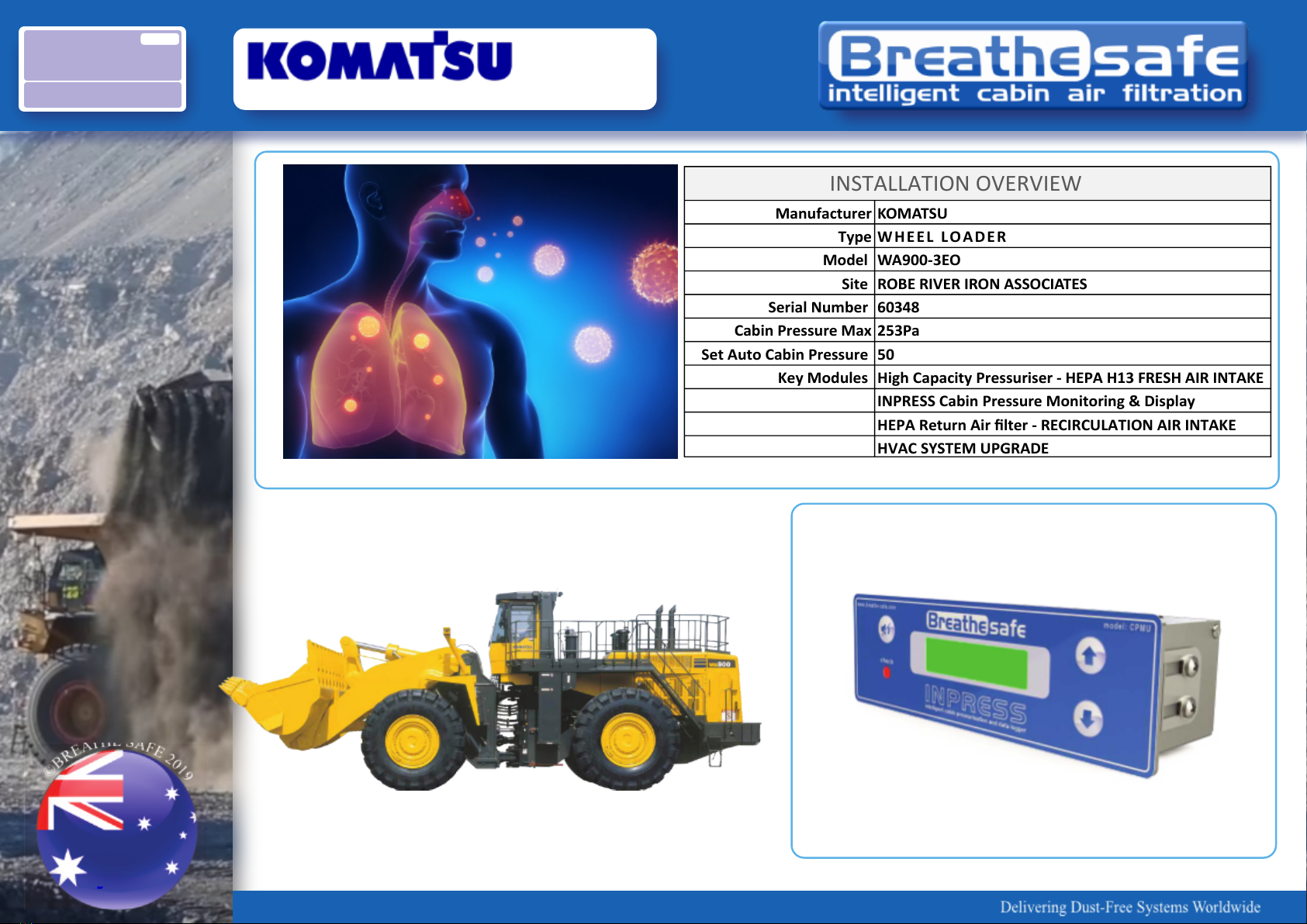
WA900-3EO
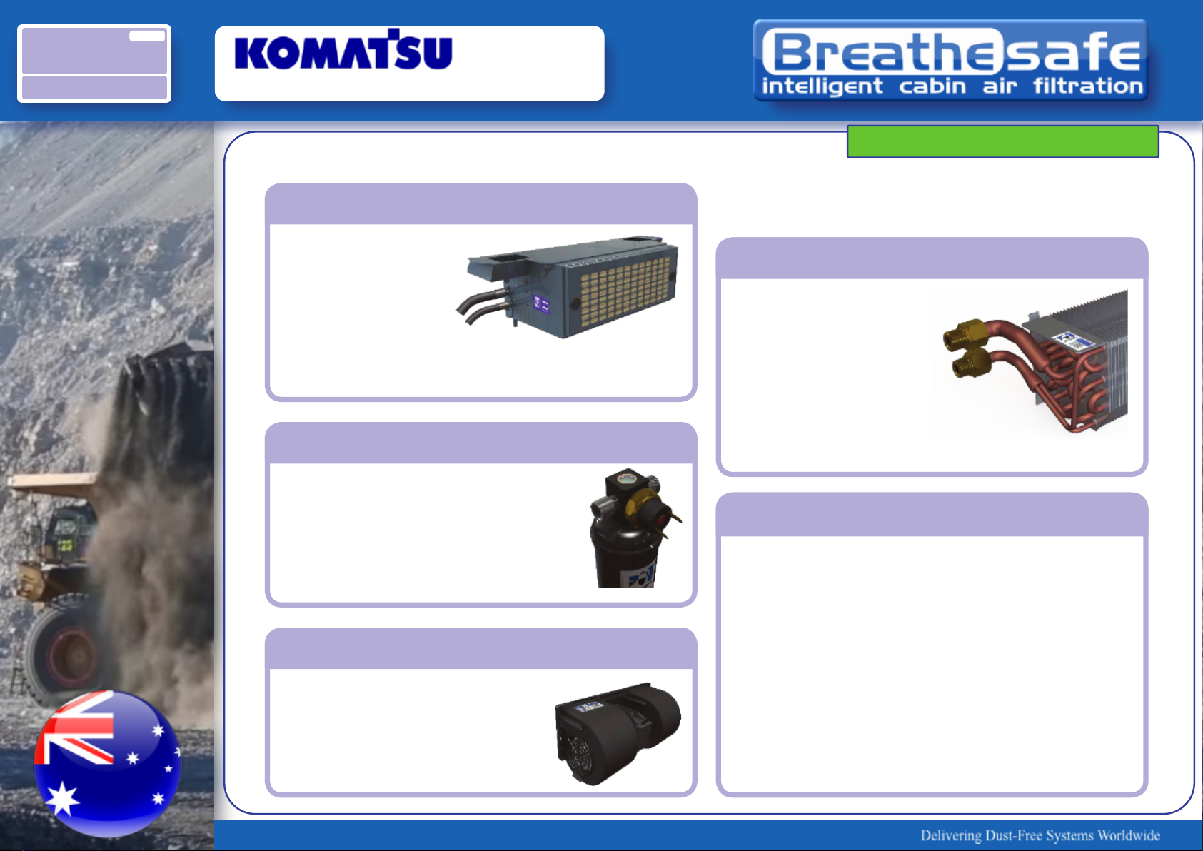
4. Evaporator Coil
The evaporator coil is constructed from
copper tubing, through which passes
the R134a refrigerant, and aluminium
ns for optimum heat transfer. The
refrigerant evaporates as it passes
through the copper tubes due to heat,
which it absorbs from the hot air owing
over and around the ns and tubes.
This absorption of heat reduces the
temperature of the air passing through
the coil, thus cooling the cab. The
refrigerant boils o becoming a low
pressure gas.
5. Compressor
The function of the compressor is to
compress the refrigerant in the system,
thus concentrating the resultant rise in
temperature. At the compressor, the
low pressure gas is changed to a high
pressure, high temperature gas. This
pressure build-up is accomplished by
having a restriction in the high pressure
side of the system. This restriction
occurs at the metered orice in the T.X.
valve.
The compressor is normally belt
driven from the engine PTO. An
electromagnetic clutch is typically
used to provide a means of stopping
the compressor from pumping when
refrigerant ow is not desired or when a
malfunction develops within the system.
6. Compressor Service Valves
Two service valves are located on the
top of the compressor cylinder head.
The valves enable the connecting
of system test gauges and also to
isolate the compressor from the rest of
the system to facilitate compressor
replacement. The high (discharge) side
service valve is quickly identied by the
smaller discharge hose routed to the
condenser, while the low (suction) side
has a larger hose coming from the
evaporator.
The valve is normally back-seated,
closing o the gauge port allowing
normal system operation. The valve
should be in this position before
disconnecting any service equipment.
The valve should be in the mid position
when the system is operating and any
service equipment is connected. Loss
of refrigerant gas will occur if the valve
is opened to this position without rst
connecting the service equipment.
The front-seated position of the valve
shuts o ow to both the gauge port
and compressor. This position is used
when isolation of the compressor
from the rest of the system is desired.
Operation of the compressor with the
valve in this position will result in severe
compressor damage due to excessive
build-up.
HEATING CIRCUIT
The heater coil (if available), is supplied with
hot water from the main engine cooling
system.
Control is via a manually operated valve in
the supply line or via the electronic
thermostat (if available), which can be
operated whilst in cooling mode to provide
some humidity control and rapid demisting.
ELECTRICAL CIRCUIT
Battery power is circuited through a circuit
breaker to the main four-position switch or
electronic thermostat (if available) which
provides for control of the three-speed
recirculating (supply) air fan.
The compressor clutch is in series with the
High Pressure / Low Pressure safety switch
and thermostat protecting the system.
A circuit breaker operates through a relay to
supply full voltage to the condenser fan
motors.
PRINCIPALS OF AIR CONDITIONING
OVERVIEW