Komax FZC KPS 8 Series Quick guide

INSTALLATION AND
INSTRUCTION MANUAL
BORE HOLE
STAINLESS
STEEL
SUBMERSIBLE
PUMPS
KPS2 Poles
50/60 Hz
Made in UAE
APPLICATION INSTALLATION MAINTENANCE
6” & 8” Series

02
Index
Index
Chapter Descripon Page No.
1Introducon 03
2General Instrucon 04
2.1 General Observaon 04
2.2 Safety Regulaon 04
2.3 Personnels Training 04
2.4 Modicaon and Manufacture of Spare Parts 04
3Safety Instrucons 05
3.1 Marking of Coded Instrucon 05
3.2 Risk Due to Nonobservance of Safety Instrucons 05
3.3 Safety Instrucon for Control, Maintenance and
Operaon 05
3.4 General Precauons 05
4 Packing and Shipment 06
4.1 Packing 06
4.2 Upliing 06
4.3 Shipment 06
5Storage & Unpacking 07
5.1 Storage 07
5.2 Stacking of Packing 07
5.3 Unpacking 07
5.4 Packing Disposal 07
6Product Descripon 08
6.1 General Descripon 08
6.2 Salient Features 08
6.3 Applicaons 08
Chapter Descripon Page No.
6.4 Operang Data 08
6.5 Pumping Liquids 08
6.6 Pump Idencaon 08
7Installaon Prerequisites 09
7.1 General Prerequisites 09
7.2 Terms of Use 09
7.3 Installaon Precauons 09
8Installaon 10
8.1 Introducon 10
8.2 General Instrucons 10
8.3 Posioning Limits, Well or Sump Requirements 10
8.4 Use of Check Valve 10
8.5 Coupling the Pump 11
8.6 Delivery Piping 11
8.7 Cable Tie/Clamp Fing 11
8.8 Lowering of the Pump 11
8.9 Installaon Depth 12
8.10 Electrical Connecons 12
8.11 Rotaon Direcon 12
8.12 Start Up 12
8.13 Above Ground Level 12
9 Maintenance 13
9.1 Maintenance and Service 13
9.2 Roune Inspecon 13
9.3 Troubleshoong 13

KOMAX products are designed, developed and manufactured
with state-of-the-art technologies in modern facilities. The pumps
are produced with great care and commitment to continuous
quality control, utilizing sophisticated quality techniques, and
safety requirements.
KOMAX is committed to continuous quality improvement and
being at service for any further information about the product
in its installation and operation or about its support products,
repair and diagnostic services.
These instructions are intended to facilitate familiarization with
the product and its permitted use. Operating the product in
compliance with these instructions is important to help ensure
reliability in service and avoid risks. The instructions may not
take into account local regulations; ensure such regulations are
observed by all, including those installing the product. Always
coordinate repair activity with skilled personnel, and follow all
plant safety requirements and applicable safety and health laws
and regulations.
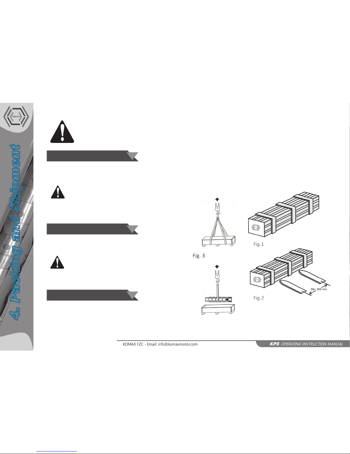
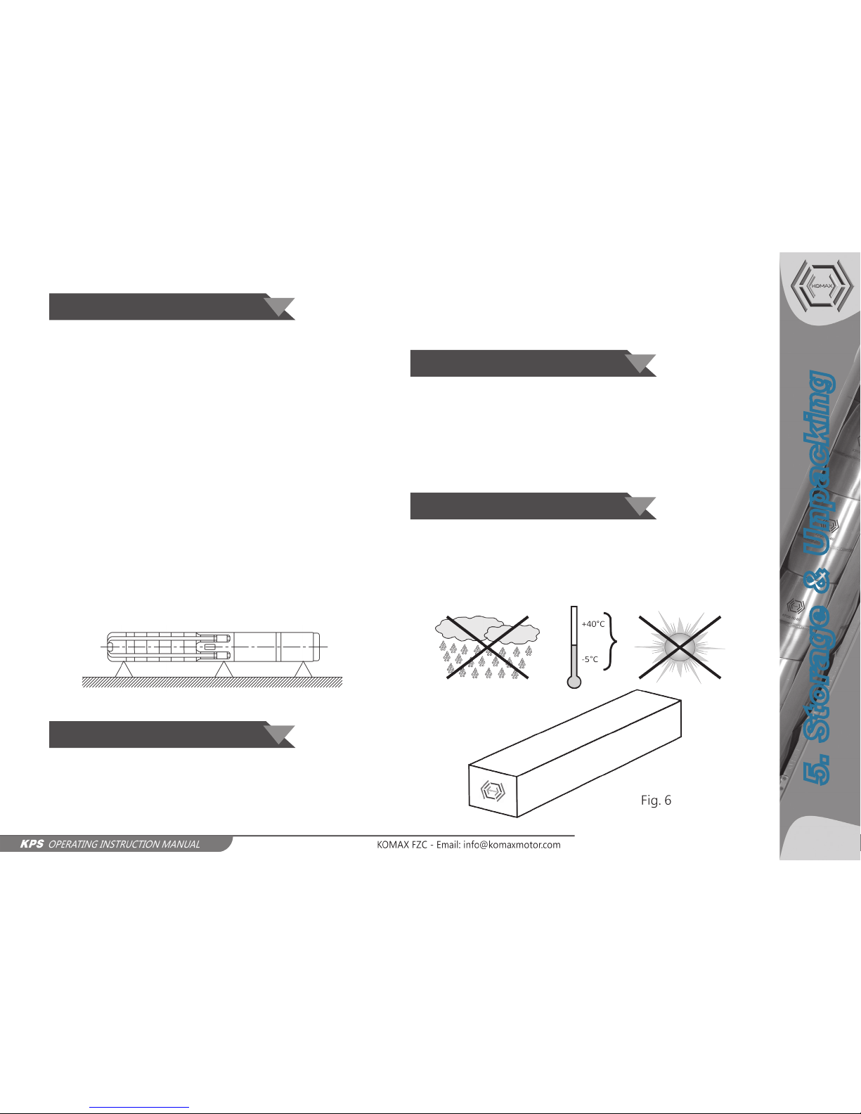
The pumps are carefully inspected and tested before
displacement. Check however the equipment at delivery against
the accompanying documents. Check box integrity before
removing the pump. Parts and accessories can be packed alone
or fastened to the box. If something is missing or damaged,
please contact immediately your local forwarding agent or local
distributor.
We strongly recommend to read it attentively and to consult
it whenever work is done on the pump. Un-observance of the
instructions here reported or improper use of the pump by
unskilled personnel may compromise pump life and proper
operation and may cause injury.
Assembly, installation, working, Extraordinary maintenance,
repair, overhaul, handling and dismantling of the pump must be
carried out by skilled technicians authorized by the Authorized
Manufacturer or Distributor/Dealer. The manufacturer does not
hold any responsibility for any damage to persons or things due
to wrong interventions carried out by unauthorized personnel or
by an improper and incorrect use of the pump.
In order to better understand the language of the present
manual, the pump user must be in possession of the necessary
qualifications in servicing and maintenance; he must have the
necessary knowledge to make out drawings and descriptions of
the manual, he must be educated and trained about the general
and specific accident prevention measures in force in the country
where the pump is installed.
The same criteria is valid for choosing the technical maintenance
personnel who, additionally, must have the necessary knowledge
of specific and specialized regulations (mechanical and electrical)
to safely carry out those interventions described in the manual.
KOMAX manufactures products in complaince to International
Quality Management System Standards as certified and audited
by external Quality Assurance organization. Genuine parts and
accessories have been designed, tested and incorporated into
the products to help ensure their continued product quality and
performance in use. As KOMAX cannot test parts and accessories
sourced from other vendors the incorrect incorporation of such
parts and accessories may adversely affect the performance
and safety features of the products. The failure to properly
select, install or use authorised KOMAX parts and accessories is
considered to be misuse. Damage or failure caused by misuse is
not covered by the KOMAX warranty. In addition, any modification
of KOMAX products or removal of original components may
impair the safety of these products in their use.
1. Introduction
1. Introducon
03

04
2. General Instruction
These operating instructions contain relevant information and
precautionary notes, Please read the manual carefully before
assembling, elecrical connection and commissioning.
This pump has been developed according to the most advanced
and latest technology, as well as in compliance with the regulation
in force. Moreover, the pump is subject to strict quality control.
These operating instructions are intended to help you better
understand the pump operation and to show you its possible
applications. The manual contains important information
necessary for reliable and long term operation. Compliance
with operating instructions is of vital importance to ensure the
reliability and long service life of the pump, as well as to avoid any
accident risk due to improier use.
This pump must not be operated beyond the limit values
quoted in the technical specification. Any indication concerning
the nature, density, the temperature, and the rate flow of the
pumped liquid, as well as the rotation speed, the pressure and
the power of the motor shall be observed. Any other instruction
contained in this manual or in the documentation enclosed to
the agreement shall be observed as well.
The name plates bears the type series, the main operatiing
data, rated power and the serial number. Please, quote this
information in all request of intervention or assistance, and when
ordering spare parts.
This manual contains essetional instructions that must be
observed during installaiton, operation and maintenance.
Therefore, This operating manual must be read and understood
both by the person in charge of assembling the pumpset and
by all qualified personnels appointed by the responsible for
installation to perform its operation. These operating instructions
must always be available on use site of the pumpset.
All personnel involved in the operation, installation, inspection
and maintenance of the unit must be qualified to carry out
the work involved. If the personnel in question do not already
possess the necessary knowledge and skill, appropriate training
and instruction must be provided. If required the operator may
commission the manufacturer/supplier to provide applicable
training.
Any reconstruction or alteration of the pumpset must be
performed by the manufacturere/supplier before being
carried out. Original spare parts and accessories supplied by
the manufacturer/supplier ensure safety. The manufacuterer/
supplier is not in any case liable for damages due to the use of
non-original spare parts!
2.1 General Observaon
2.2 Safety Regulaons
2.3 Personnels Training
2.4 Modicaon & Manufacture
of Spare Parts

Read these instructions carefully before installation. It contains
fundamental instructions for installation, operation and
maintenance. The symbols shown below together with the
words "DANGER" and "WARNING" indicate a risk of danger if
instructions are not followed.
DANGER Risk of electric shock if given instructions
not followed.
DANGER Risk of injury and/or damage to person
and/or property if instructions are not followed.
WARNING Risk of damage to the pump and/or
systems if instructions are not followed.
Nonobservance of safety instructions may cause physical and
material damages, as well as enviromental pollution. Non-
compliance with safety instructions will also lead to the complete
loss of any warranty right.
In particular, the inobservance of the above mentioned
instructions may for example result in:
• Failure of main pumpset function.
• Failure of maintenance procedures.
• Hazard of electrical, mechanical or chemical nature.
All safety instructions contained in this manual shall be observed,
as well as any other national regulation on accident prevention,
and any internal regulation on the use of pumpset and on
occupational safety.
The person in charge must verify that all maintenance, inspection
and installation works are performed by qualified and authorised
personnel. Before performing these works, the personnel must
be aware of the content of this manual.
All interventions on the pumpset must be carried out only during
total standstill of the mentioned pumpset. Strictly observe the
shutdown procedure described in this manual.
Pump conveying fluids hazardous to health must be
decontaminated. Immediately after completion of work, all safety
and protective devices must be reinstalled and/or reenabled.
IiII
ATTENTION: The user and the
maintenance personnel are
obliged to carefully follow the
regulations referred to laws
and accident prevention norms in force in the
country where the pumpset is in use/installed.
Further more they are obliged to:
• Neither remove nor defuse mechanical
and electrical protections or other.
• Pay attention to the warnings reported on
the pump and in the manual.
• Always use individual protection measures
like accident prevention shoes and gloves.
3. Safety Instruction
05
3.1 Marking of Coded Instrucon
3.2 Risk Due to Nonobservance
of Safety Instrucons
3.3 Safety Instrucons for Control,
Maintenance and Operaon
3.4 General Precauons

06
4. Packing and Shipment
PACKING, LIFTING, HANDLING, SHIPMENT AND
UNPACKING ARE EXCLUSIVELY ENTRUSTED TO
EXPERT PERSONNEL WHO KNOWS BOTH THE
PUMP AND THE MANUAL VERY WELL.
According to their dimensions, pumps are shipped as follows:
• In a wooden crate/carton box.
• In wooden pallets
ATTENTION!
Gross weights is mentioned on the wooden case/carton box.
(see Figure. 1)
Packed pump can be lifted and transported by fork lift trucks.
(see Figure. 2)
ATTENTION!
The chosen trucks must be suitable for a safe lifting and handling,
considering the weights reported on the packing. (see Figure. 2)
Before transportation, please checks:
• Pump weight
• Pump overall dimensions
• Suitability of lifting points
KOMAX submersible pumps and their accessories (if included)
are packed in wooden crate/carton box suited for transportation
to avoid any damage on the way. However, we recommend to
inspect carefully the pump at delivery.
The pump should be handled with equipment suited to its
weight and to the shape of its box (see Figure 1) to avoid possible
damages due to mishandling. Lifting by hand is allowed only for
weights lower than 20 kilograms. For higher weights, we suggest
to lift the pump as shown in Figures 2 and 3.
4.1 Packing
4.2 Upliing
4.3 Shipment

Packing must always be kept in covered and protected places
with temperatures between -5 °C and +50 °C, avoiding direct
exposure to the sun rays and rain. (see Figure. 6)
During storage, please observe the following precautions:
• Store the pump in a covered, dry and airy environment.
• Pump should not be stored or installed with lower
temperatures or for periods longer than 12 months;
however, if this is unavoidable turn the pump shaft by hand
once a month.
• Pump stored for more than 12 months must be checked
by an authorized shop before installation.Avoid the pump
to be bent when it is not packed, since this may cause the
misalignment and the damage of the the pump itself.
• Protect the pump from direct sunlight and rain.
• If the pump has been unpacked, it should be stored
horizontaly, adequately supported. During storage, the
pump can be supported as shown in Fiqure. 5
Fig. 5
The type of packing being utilized permits the possibility of
stacking up to 4 cases on top of each other inside the warehouse,
thanks to the kind of packing utilized, provided that they are
properly piled and insured against falling. Inside the truck bodies
and in the containers can be stacked up to 5 cases (except for the
pallet, provided that they are well strapped and insured against
falling.
When the goods arrive, please check if the parts are not
damaged during the transportation and verify every part listed
in the delivery note.
Unpack carefully taking all the necessary precautions in order
to avoid any damage to persons or pump parts (during the
unpacking, please avoid making fall the parts from the crate/box).
The wood of crate or the wood of pallet can be re-used or recycled
in accordance with the laws in force in the country where the
pump is installed. Other materials like strap, polystyrene and
plastic have to be disposed according to the laws enforced in the
country.
5. Storage & Unpacking
07
5.1 Storage
5.2 Stacking of Packing
5.3 Unpacking
5.4 Packing Disposal

08
6. Product Description
The submersible pumps are multistage pumps working
counterclockwise rotation direction (observing from the delivery
side) directly coupled any 6 inch NEMA standard submersible
motors.
The new series of 6” and 8” stainless steel submersible
pump KPS6 and KPS8 has been designed and produced
according to the market requirement. Compact, reliable
and hydraulic design are ensure the high overall eciency
and less energy consumpon are making the low running
cost of pumping system. Heavy duty casted stainless steel
top and boom and fabricated impellers and diuser for
corrosion resistance and for long and trouble free life.
These submerisble pumps are designed for a wide range of
applications, such as the supply of water to private homes,
water systems and industries. These pumps are necessary in
case of lowering of the groundwater level, as well as for pressure
increase. Detail as under
Domesc and industrial water supply
Industrial cooling process
Fire ghng systems
Shower and running irrigaon
Agriculture and sprinkler systems
Mining industry, drainage and de-watering
Capacity: upto 132 m3/h
Head: upto 577 meters
Power: upto 82 kW
Minimum water temperature: -5 ° C
Maximum water temperature: 50 ° C
Maximum sand contents: 55 grm/m3
Direcon of rotaon: CCW facing delivery side
Minimum recommended head of water above pump
sucon: 1 meter
Pump are design for pumping clear and cold water that is free
of air and gasses, thin, non-aggrassive and non-explosive liquid
without solid particles or fibres.
Decreased pump performance and life expectancy can occur if
the water is not cold and clear or contain air and/or gasses.
The maximum sand content in the water must not exceed
50 g/m3. A greater sand content in the water reduces the service
life of the pump and increases the risk of blocking.
When pumping liquids with a density higher than that of water,
motors with correspondingly higher outputs must be used.
6.1 General Descripon
6.3 Applicaons
6.4 Operang Data
6.2 Salient Features
6.5 Pumping Liquids
KP S 6 - 50 / 12
Nos. of Impellers/Stages
Nominal Flow in m3/h
Komax Deepwell Submersible Pump
Stainless Steel Version
Nominal Pump Dia in Inches
6.6 Pump Idencaon

For submersible pump's reliable, efficient and trouble free and
long operational life, please ensure the following:
1. A suitable operating environment.
2. An appropriate size of submerisble motor.
3. Completely submerged in cold & clear water.
4. An adequate supply of electricity
Before installation please make sure that:
• The borehole is of appropriate size; ideally the borehole
should have an ID of 8 inch for KPS6 and 10 inch for KPS8.
If the borehole is very large or if the pump-set is to be
installed in an open well or tank, the use of cooling jacket
is recommended.
• The brake horse power of the motor is at least 10% greater
than that the shaft power of the pump.
• The bore is properly treated and tested for the required
discharge.
• The borehole is perfectly vertical and there is no hindrance
inside such as fallen wood etc.
• There is easily accessible IN/OUT from the installation
chamber.
Before starting the installation carefully check the bore visually,
measure the static water level and the total bore depth, also
examine the strata chart of the borehole to locate the blinds and
filters/stainer. Record this obtained data carefully.
Also recheck the intended depth of lowering with the data
obtained and mark the lowering depth of the pump-set on the
strata chart of the borehole for record.
• The water temperature must not exceed 50 °C.
• The maximum density of the pumped liquid must not
exceed 1000 Kg/m3.
• pH of the pumped liquid should be 6 – 8.
• The Supply Voltage variation must be under +6% & -10%.
• All the necessary protections such as overload protection,
under and over voltage protection, phase asymmetry
protection and dry run protection must be installed in the
control unit.
• The motor pump-set should not be operated for more than
3 minutes in zero flow state.
• The fluid flow velocity over the pump-set should be from 16
cm/sec to 96 cm/sec.
• Make sure that the power cable supplied with the motor
pump-set is in good condition and the insulation is not
damaged.
• The installation tools should be placed in proper order for
easy access.
• In order to prevent possible water hammers able to
damage thrust bearing, the use of check valve is highly
recommended.
7. Installation Prerequisites
09
7.1 General Prerequisites 7.2 Terms of Use
7.3 Installaon Precauon

10
8. Installation
THESE INTERVENTIONS MUST BE EXCLUSIVELY ENTRUSTED TO
SKILLED TECHNICIANS; IF THEY ARE CARRIED OUT BY OTHER
PERSONS, THERE CAN BE DANGEROUS SITUATIONS AND
SERIOUS DAMAGES TO PERSONS AND/OR TO THE PUMP
Submersible pumps and motors are carefully constructed of
high quality materials and are designed to give long trouble free
life. This manual describes the basic procedure for installing,
operating, and maintaining a submersible pump and motor.
Failure to read, understand, and follow the instruction in this
manual, the motor manual, and the instructions for accessory
equipment can cause personal injury, poor performance of the
equipment, shortend life of the equipment, and can void the
warranty on the equipment.
A major portion of the works associated with submersible motor
installation, operation, and maintenance is electrical. It is not
the intent of the manual to provide detailed instruction for this
electrical work.
Read the motor manual and the instructions for other equipment
that is part of the installation and integrated these instructions
with the basic instructions contained in this manual.
Hoisting equipment cable of controlled hoisting and lowering of
the combined weight of the pump, motor, drop cable, column
pipe, and discharge head.
The height of the equipment must be sufficient to
accommodate the longest component to the installed.
Pipe elevators (or equivalent) and lifting bail (or equivalent) for
handling and installing sections of column pipe. The elevators
and lifting bail must be capable of carrying the combined weight
of the pump, motor, drop cable and column pips.
The pump is suitable for both vertical and horizontal installation,
however, the pump should never be installed inclined downwards.
The well should developed with a test pump prior to installing
the submersible pump. Test pumping the well serves several
purposes. It removes the excess sand encountered during the
initial pumping of the well. Attempting to pump mud or sand
with a submersible pump can bury the pump motor causing it
to overheat and burnout. Test pumping also provides a means
of determining the capacity and drawdown (lowering of the
water level in the well during pumping). Pumping sand or other
abrasives with a submersible pump will shorten the life of the
pump and can void the warranty.
The well capacity should equal or exceed the pump capacity. If
the pump removes water at a higher rate than the well produces,
the drawdown will be excessive and the pump will caviate or
"starve" resulting in damage to the pump and motor
The well must be deep enough so that the pump suction is at
least 10 feet below the expected drawdown level. The lower end
of the pump should be at least 10 feet from the bottom of the
well.
At the time of installation of submersible unit minimum one
check valves always be used. If the pump does not have a built-in
check valve, a line check valve should be installed in the discharge
line within 25 feet of the unit and below the water draw down
level. For deeper settings, more than one check valves may be
required (as per manufacturer’s recommendations).
Internal pump check valves or spring loaded check valves close
8.2 General Instrucons
8.3 Posioning Limits, Well
or Sump Requirements
8.1 Introducon
8.4 Use of Check Valve

quickly and help eliminate water hammer. Check valves are used
to hold pressure in the system when the pump stops. They also
prevent backspin, water hammer and upthrust. Any of these
can lead to early pump or motor failure. Although drilling the
check valves or using drain-back check valves may prevent back
spinning, they create upthrust and water hammer problems.
Following are the main disadvantage of not using a check valve,
leaking check valve, or drilled check valve with submersible
pumps.
• The water in the drop pipe and the water in the system can
flow back in the discharge pipe when the motor stops, this
can cause the pump to rotate in a reverse direction. If the
motor is started while it is backspinning, an excessive force
is placed across the pump-motor assembly that can cause
impeller damage, motor or pump shaft breakage, excessive
bearing wear tear etc,
• The pumpset starts under a zero head condition, this causes
an uplifting or upthrust on the impeller-shaft assembly in
the pump. This upward movement carries across the pump
motor coupling and creates an upthrust condition in the
motor, repeated upthrust can cause premature failure of
both the pump and the motor.
Place the pump on the motor in order that they are positioned
along the same axis and insert the motor shaft in the pump shaft
joint; the coupling must not be forced. Tighten the screws or the
nuts that diagonally fix the pump motor flanges with a driving
torque as quoted in below table.
Motor Type Screw Size Driving Torque Nm
Motor 4 inch M8 18
Motor 6 inch M12 100
Motor 8 inch M16 200
If the pump is already coupled to the delivery piping and you use
a chain pipe wrench, tighten the pump, holding it only by the
delivery opening. The threaded pipes must be connected in such
a way as to support the unscrewing action due to the starting
and stopping of the pump. The thread of the pipe, which has to
be screwed into the pump, should not be longer than the thread
of the pump.
After screwing the pipe into the delivery opening, tighten the
screw assembled to avoid the loosening of the first section of the
pipe. When plastic pipes are used, the pump should be secured
by an unloaded rope to be fastened to the delivery opening.
Use cable tie/clamp every 3 meters to fix the cable to the support
rope or to the delivery pipe. Once the cable has been fastened,
cut off the remaining part of the clip.
If plastic pipes be used, do not stretch the electric cable and the
support rope in order to avoid the tearing of the electric cable
due to the plastic pipes stretch caused by the weight of the water
contained in it.
When flange pipe used, the cable tie/clamp must be positioned
before and after each flange.
Verify that the well is not clogged along its total length. Lower the
pump into the well, paying attention not to damage the electric
cable.
Be extremely careful not to scrape or damage the
submersible power cable, hold the cable up away
from the well casing at the time of lowering.
8. Installation
11
8.5 Coupling the Pump
8.6 Delivery Piping
8.7 Cable Tie/Clamp Fing
8.8 Lowering of the Pump

12
8. Installation
The dynamic water level must always be above the suction
support of the pump. The pump suction is atleast 3 meter below
the expected drawdwon level. The lower end of the pump should
be at least 3 meter above from the bottom of the well.
Block the delivery pipe with proper hangers on the well head.
Loosen the support rope and fix it to the ground work.
The electrical connections should be carried out by an authorized
electrician according to the regulations in forece. Supply voltage,
current and cosɸ are mentioned on the motor name plate that
has to be kept within the electrical panel.
The motor must be earthed and connected
to the electrical panel.
When the pump has been connected to the power supply,
establish the current direction of rotation as follow.
1. Start the pump and check the head/pressure supplied with
gate valve not completely closed.
2. Stop the pump and interchange two of the phase
connections.
3. Start the pump and repeat the setp 1, with gate valve in the
same position.
4. Stop the pump, compare the results obtained in step 1 and
step 2. The connection, which supplies the highst head/
pressure, is the correct one.
The pump must not be started until the suction
support has been completely submerged.
When the pump has been installed and submerged, it can be
started with the gate valve closed to one third (1/3). If there are
impurities in the water, the gate valve should be opened gradually
until the water becomes clearer. The pump should not be stopped
until the water is completetly clean again, since otherwise the
pump parts and the non-return valve may be damaged.
If the pump flow rate is higher than that of the well, the use of a
protection device against dry operation is recomended. Without
any protection against dry operation, the water level falls under
the suction support and the pump sucks air. In long term, this
causes damages due to poor cooling and lubrication.
The system must be designed to match the flow and pressure
produced by the pump. Systems that allow the pump to operate
at low pressure/high flow conditions cans cause cavitation or up-
thrust problems and damage the pump or the motor. Systems
that allow the pump to run at high pressure/low flow conditions
(i.e. operating at or very near shutoff) for extended periods of
time can cause the motor to overheat and burn out. A pressure
relief valve should be installed if the pump shutoff pressure
exceeds the pressure rating of the system.
The system must be designed so that the pump is not cycled ON
and OFF excessively.
8.10 Electrical Connecons
8.9 Installaon Depth
8.13 Above Ground Piping
8.11 Rotaon Direcon
8.12 Start Up

A submersible pump, properly installed in a clean well, will run
for a long period of time with a minimum of attention. However,
conditions are not always ideal and can change for the worse in the
course of time.
Submersible pump usually run unattended and automatic control
devices are used to stop and start the pumpset and to protect it from
abnormal conditions such as overloads, line faults, etc. It is important
that these automatic devices be adjusted properly and maintained in
good working condition. Failure of these devices can easily cause the
failure of a pump that is in excellent condition. Unfortunately these
protective devices may not protect the installation against all of the
hazards that may be encountered.
In order to assure that potential problems are identified and
corrected as soon as possible, a program for regular inspection and
testing of the unit should be established. The frequency of inspection
and testing will vary depending on the complexity of the controls,
the consequences of a failure, the cost of making the inspections
and tests, the age and condition of the unit, the results of previous
inspections and tests, and the operating philosophy of the owner/
operator.
On a periodic basis, the unit should be given a quick inspection, that
routine inspection should include the following checks.
• Check for any obviously abnormal conditions such as gross
leakage or gross damage.
• Check that the unit is not making excessive noise.
• Check the electric panel for alarms, blown fuses, etc.
• Check the electrical system for signs of overheating or other
abnormal conditions.
Any problems noted should be carefully investigated and corrected
immediately.
Note that a large portion of the probable causes are electrical and also
that a large portion of these electrical problems are due to above ground
equipment. Before going to the time and expense of pulling the unit from
well, be sure that all above ground problems have been corrected and
that a thorough diagnosis has been made indicating that the problem is
underground.
Sr: # Possible Cause Recommended Remedy
1. Zero or poor ow rate
1.1 Well water level too low
Wait until well water level is
restored, or if possible, lower the
pump further
1.2 Sucon screen clogged Pull out the pump and clean it
1.3 Delivery valve closed or blocked Find and replace the defecve
valve
1.4 Pump silted up/jammed Pull out the pump and clean it
1.5 Wrong direcon of rotaon Carry out direcon as in 8.11
1.6 Pump capacity exceeds well
capacity
Replace pump with one of the
lower capacity
2. Poor pressure/not reaching designed head
2.1 Wrong direcon of rotaon Carry out direcon as in 8.11
2.2 Leak in system Locate leak and repair them
2.3 Worn pump Pull out the pump and overhaul it
3. Pump start and stop too frequently
3.1 Well water level too low
Wait until well water level is
restored, or if possible, lower the
pump further
3.2 Pump capacity exceeds well ca-
pacity
Replace pump with one of the
lower capacity
3.3 Pressure switch or level control
improperly set
Reset or replace if found
damaged
4. Excessive current absorbed by the pumpset
4.1 Pump silted up/jammed Pull out the assembly and clean it
4.2 Wrong direcon of rotaon Carry out direcon as in 8.11
4.3 Mechanical fricon Pull out the pump and overhaul it
9. Maintenance
13
9.2 Roune Inspecon
9.1 Maintenance and Service 9.3 Troubleshoong

14
Important Notes
Important Notes

Important Notes
15
Important Notes

Plot No. P4-11, SAIF Zone,
P.O Box No. 120065, Sharjah
United Arab Emirates
Tel. : +971 6 5578212-3
Fax : +971 6 5578422
Email: info@komaxmotor.com
Website: www.komaxmotor.com
Edion: 03/2015
This manual suits for next models
1
Table of contents
Popular Water Pump manuals by other brands

Pentair
Pentair Nocchi DOMINATOR 4 Translation of the original instructions

Dynojet
Dynojet Power Commander III installation instructions

DeKo
DeKo DKCSP03 instruction manual

Grundfos
Grundfos STC Series Installation and operating instructions

Villager
Villager VSPP 15000 Original instruction manual

Pentair
Pentair Myers MES100 Installation and operator's manual

Grundfos
Grundfos CMBE Series Installation and operating instructions

Brinkmann
Brinkmann BFT750 operating instructions

Everbilt
Everbilt ZE00804 Use and care guide

Lincoln
Lincoln A 4417 manual

Franklin Electric
Franklin Electric FBSGF Series owner's manual

DP Pumps
DP Pumps Hydro-Unit Premium Installation & operating manual