Kompact AMC User manual

EM00136452 Rev.1.0
EN
DE
ES
FR
IT
PT
TR
RU
KOMPACT AMC
INSTALLATION MANUAL
HANDBUCH
MANUAL DE INSTALACION
MANUEL D’INSTALLATION
MANUALE D’INSTALLAZIONE
MANUAL DE INSTALAÇÃO
KULLANIM KLAVUZU
РУКОВОДСТВО ПО УСТАНОВКЕ И ЭКСПЛУАТАЦИИ

EM00136452 Rev.1.0

EM00136452 rev.1.0 EN
1
AB
E
C
G
I
F
D
H
INSTALLATION AND START-UP MANUALFOR KOMPACT AMC DOSING
PUMP
Packing contents:
A. Opaque hose for connecting the pump’s outlet to the
injection point
B. Transparent hose for suction and for connecting the
bleeding valve up for manual priming
C. Injection fitting
D. Hose connection kit
E. Bottom filter
F. Wall mounting bracket
G. Anchors for securing the pump to the wall
H. Screw protection caps
I. Instructions Manual
FOR SPECIFIC HYDRAULIC FEATURES SEE THE LABEL ON THE PUMP
INTRODUCTION
The pump is composed of a part that houses the control electronics and the magnet and a hydraulic side always in contact with
the liquid to be dosed.
Check the rating plate of the main features of your pump
1. Adjustments area
2. Dosing head
3. Priming valve
4. Delivery connector
5. Suction connector
6. Base fixing bracket (optional)
We recommend checking the chemical compatibility between the product and the materials in contact.
PUMP HEAD MATERIALS
• Pump body: PVDF-T
• Valves: PVDF-T
• Balls: Ceramic
• Diaphragm: PTFE
SPECIFICATIONS
• Weight: 1.5 Kg
• Power Supply: 100 - 240 Vac (50-60 Hz) – 24Vac/dc
• Consumption: 13W @ 100 Vac – 19W @ 240 Vac – 12W @ 24 Vac/dc
• Fuse: 2A (100 ÷ 240 Vac) / 3,15 (24Vac/dc); 250V; T 5x20
• Protection rating: IP65
• Level control input: Dry contact (on-off)
• Pulse input: Dry contact (on-off) maximum frequency 80Hz

EM00136452 rev.1.0 EN
2
READ THE FOLLOWING WARNINGS BEFORE INSTALLING
OR PERFORMING MAINTENANCE ON THE PUMP.
I
WARNING: BEFORE DOING ANY WORK ON THE PUMP, ALWAYS FIRST DISCONNECT THE
POWER SUPPLY CABLE.
I
WARNING: WE RECOMMEND INSTALLING THE PUMP IN A VERTICAL POSITION TO ENSURE
PROPER OPERATION.
I
ATTENTION: PRODUCT INTENDED FOR PROFESSIONAL USE BY SKILLED PERSONNEL.
I
ATTENTION: MAINTENANCE WORK ON THE PUMP MUST BE CARRIED OUT BY AUTHORISED AND
TRAINED PERSONNEL ONLY.
- H2SO4 SULPHURIC ACID All the pumps are tested with water. Before dosing chemical products that may react
with water, dry all the internal parts of the plumbing thoroughly.
- Install the pump in a zone where the environment temperature does not exceed 40ºC and the relative humidity is below
90%. The pump has an IP65 protection level. Avoid installing the pump directly exposed to sunlight.
- Install the pump so that any inspection and maintenance operations are easy to carry out, then secure the pump firmly in
order to prevent excessive vibrations.
- Check that the power supply available in the network is compatible with that indicated on the pump label.
WIRING
Input A = Power
supply 100 - 240 Vac
(50-60 Hz) or
24Vac/dc
Input B =
Pulses free from
voltage
(pulse emission meter
or Hall sensor)
Input C = Level
control probe input
The pump must be connected to a
power supply that complies with the
information indicated on the label on
the side of the pump. Failure to
respect these limits may cause
damage to the pump itself.
The pumps have been designed to
absorb small over voltages.
Therefore, in order to prevent the
pump from being damaged, it is
always preferable to ensure that the
pump does not have a power source
shared with electrical appliances that
generate high voltages.
Connection with the three-phase
380V line should only be made
between phase and neutral.
Connections MUST NOT be made
between phase and ground.
123 4 56
F
1
Output
voltage 10
Vcc
Hall sensor or similar input
(output voltage 10 Vcc; maximum
current 5 mA)
2
Signal
4
GND
3
Not used.
2
Pulses free from voltage
(pulse emission meter; dry contact: on-off,
maximum frequency 80Hz)
4
5
Level control probe input
(Dry contact: on-off)
6
F
Fuse: 2A (100 ÷ 240 Vac) / 3,15 (24V); 250V; T
5x20

EM00136452 rev.1.0 EN
3
DOSING MODE SETTINGS
A switch (shown in the figure) that regulates the dosing mode of the pump
is present in the part relative to the electrical connections on the circuit.
The two different modes are:
Constant (switch in position C)
The pump constantly dispenses the percentage selected with a
potentiometer.
Proportional (switch in position P)
The pump doses proportionally to the input signal (Pulse emission meter).
PLUMBING CONNECTIONS
13
4
6
3
12
5
2
11
6
4
8
4
6
6
43
14
5
10
9
7
5
5
1
1. Injection point
2. Injection fitting
3. Seal
4. Pipe holder
5. Pipe clamp
6. Ring nut
7. Delivery hose (rigid)
8. Delivery valve
9. Pump body
10. Bleed valve
11. Suction valve
12. Suction hose (soft)
13. Bottom filter
14. Bleed valve connector
Fixing templates wall bracket
After around 800 hours of work, tighten the bolts on the pump body, applying a tightening torque of 3 Nm.
When making the plumbing connections, make sure that you follow the instructions below:
- The BOTTOM FILTER must be installed so that it is always positioned 5-10 cm from the bottom, in order to
prevent any formation of deposits.
- Installation of the pump suction head is recommended for pumps with very low flow rates. In particular, when dosing
products which develop gas (e.g. sodium hypochlorite, hydrazine, hydrogen peroxide, etc.).
- If you need to use longer hoses than those provided in the installation kit, it is important that you use hoses of the same
dimensions as those supplied with the pump. If the DELIVERY HOSE may be exposed to the sun’s rays, we recommend
using a black hose able to withstand ultraviolet rays
- It is advisable to position the INJECTION POINT higher than the pump or tank.
- The INJECTION VALVE, supplied with the pump, must always be installed at the end of the delivery line on of the dosing
flow.

EM00136452 rev.1.0 EN
4
START-UP
Once all the aforementioned operations have been completed, the pump is ready to be started.
Priming
- Start the pump.
- Open the priming connector by turning the knob in a counter-clockwise direction and wait for liquid to come out of the pipe
connected to it.
- Once you are sure that the pump is completely full of liquid, you can close the connector and the pump will begin to dose.
TROUBLESHOOTING
Problem
Possible Cause
Solution
The pump is working properly but the
dosage is interrupted
Blocked valve
Clean the valves or replace them if it is not possible
to remove the build-ups
Excessive suction height
Position the pump or tank so as to reduce the
suction height
Excessive liquid viscosity
Reduce the suction height or use a pump with a
bigger flow capacity
Insufficient flow capacity
Leakage from the valve
Check that the ring nuts are properly tightened
Excessive liquid viscosity
Use a pump with a bigger flow capacity or reduce
the suction height
Valve partially blocked
Clean the valves or replace them if it is not possible
to remove the build-ups
Irregular pump flow capacity
Transparent PVC hose on
delivery
Use an opaque PE pipe on delivery
Broken diaphragm
Excessive back-pressure
Check the system pressure. Check whether the
injection valve is blocked. Check whether there are
any blockages between the delivery valves and the
injection point.
Operation without liquid
Check the presence of the foot filter (valve). Use a
level probe that blocks the pump when the chemical
product runs out in the tank
Membrane not secured
correctly
If the membrane has been replaced, make sure that
the same is correctly tightened.
The pump does not switch on
Insufficient power supply
Check whether the pump plate data corresponds to
that of the electricity network.
KOMPACT AMC – Control Panel
CONSTANT MODE (switch in position C)
The pump dispenses the percentage selected manually with a potentiometer.
Steady green LED switches off with every stroke that the pump runs.
Flashing Green led with the potentiometer to 0.
PROPORTIONAL MODE 4:1 (switch in position P)
After four received external pulses (pulse emission meter) and with the potentiometer at 100% of its regulation, it
runs a stroke.
The potentiometer permits an increase in the number of received external pulses, after which the pump runs a
stroke.
Below are some examples of operation:
Potentiometer [%]
1 stroke / Pulses
100
4
50
8
10
40
LED for dosing indication
and level probe alarm
signal
Potentiometer for% flow rate
regulation

EM00136452 rev.1.0 EN
5
Steady orange LED switches off with every stroke that the pump runs.
Flashing orange LED with the potentiometer at 0.
calibratio
n
meter
Qn
max pul/min available from
meter
[Qn x pul/l]
max pump frequency
[4 pulse meter = 1 pulse
pump]
max ppm available
to max frequency
5
0.69
pul/l
l/pul
pul/l
l/pul
pul/l
l/pul
size
m3/h
4
1
100
1000
4
1
100
1000
4
1
100
1000
1/2"
1.5
100
25
25
6
521
130
3/4"
2.5
167
42
42
10
521
130
1"
3.5
233
58
58
15
521
130
1"1/4
5
333
83
83
21
521
130
1"1/2
10
667
167
160
42
500
130
2"
15
1,000
250
2.5
160
63
0.63
333
130
1.3
2"1/2
25
4.2
1.04
1.3
3"
40
6.7
1.67
1.3
4"
60
10.0
2.50
1.3
6"
150
2.5
0.63
0.13
ALARMS
Display
Cause
Interruption
Steady red LED switches on.
End level alarm.
Restore liquid level.

EM00136452 Rev.1.0 DE
1
AB
E
C
G
I
F
D
H
INSTALLATIONS- UND INBETRIEBNAHMEANLEITUNG FÜR DIE
DOSIERPUMPE SERIE KOMPACT AMC
Packungsinhalt:
A. Undurchsichtiger Schlauch für den Anschluss des
Pumpenausgangs an den Einspritzpunkt
B. Transparenter Schlauch für die Ansaugung, für den
Anschluss des Auslassventils und für die manuelle
Befüllung
C. Anschluss Einspitzung
D. Satz Schlauchanschlüsse
E. Bodenfilter
F. Bügel für Wandmontage
G. Dübel für die Montage des Wandbügels
H. Schraubenschutzkappen
I. Anleitung
HYDRAULISCHE BESONDERHEITEN FINDEN SIE UNTER DER BEZEICHNUNG AUF DER PUMPE
EINLEITUNG
Die Dosierpumpe besteht aus einer Steuereinheit, in der die Elektronik und der Magnet sowie ein Teil der Hydraulik
untergebracht sind, immer in Kontakt mit der zu dosierenden Flüssigkeit.
Prüfen Sie anhand der Angaben auf dem Typenschild die Haupteigenschaften
Ihrer Pumpe
1. Einstellbereich
2. Dosierkopf
3. Befüllventil
4. Druckanschluss
5. Ansauganschluss
6. Gestell für Unterbau (optional)
Wir empfehlen eine Prüfung der chemischen Kompatibilität zwischen dem dosierten Produkt und den
Kontaktmaterialien.
MATERIALIEN DES PUMPENKOPFES
• Pumpengehäuse: PVDF-T
• Ventile: PVDF-T
• Kugeln: Keramik
• Membran: PTFE
TECHNISCHE MERKMALE
• Gewicht: 1,5 Kg
• Stromversorgung: 100 ÷ 240 Vac (50-60 Hz) - 24Vac/dc
• Leistungsaufnahme: 13W @ 100 Vac – 19W @ 240 Vac – 12W @ 24 Vac/dc
• Sicherung: 2A (100 ÷ 240 Vac) / 3,15 (24Vac/dc); 250V; T 5x20
• Schutzgrad: IP65
• Eingang Füllstandskontrolle: Trockenkontakt (on-off)
• Impulseingang: Trockenkontakt (on-off) Höchstfrequenz 80Hz

EM00136452 Rev.1.0 DE
2
VOR DER INSTALLATION ODER
WARTUNGSARBEITEN AN DER PUMPE AUFMERKSAM LESEN
I
ACHTUNG: VOR DER INSTALLATION ODER DER WARTUNG DER PUMPE IMMER ZUNÄCHST DIE
VERSORGUNG TRENNEN.
I
ACHTUNG: WIR EMPFEHLEN DIE INSTALLATION DER PUMPE IN EINER VERTIKALEN POSITION
UM EINEN ORDNUNGSGEMÄSSEN BETRIEB ZU GEWÄHRLEISTEN.
I
ACHTUNG: DAS PRODUKT IST AUSSCHLIESSLICH FÜR DEN PROFESSIONELLEN GEBRAUCH
DURCH QUALIFIZIERTES PERSONAL BESTIMMT.
I
ACHTUNG: DIE WARTUNG DER PUMPE DARF AUSSCHLIESSLICH DURCH QUALIFIZIERTES UND
AUTORISIERTES PERSONAL DURCHGEFÜHRT WERDEN.
- H2SO4 SCHEFELSÄURE Vor der Dosierung chemischer Produkte, die mit Wasser reagieren können, müssen alle
internen Komponenten der Hydraulik getrocknet werden.
- Umgebungstemperatur unter 40°C. Relative Luftfeuchte unter 90%. Schutzgrad: IP65 Die Pumpe nicht so installieren, dass
sie direkt Sonnenstrahlen ausgesetzt ist.
- Die Pumpe gut befestigen, damit übermäßige Vibrationen vermieden werden.
- Versorgungsspannung und -druck der Anlage müssen mit den Angaben auf dem Etikett der Pumpe übereinstimmen.
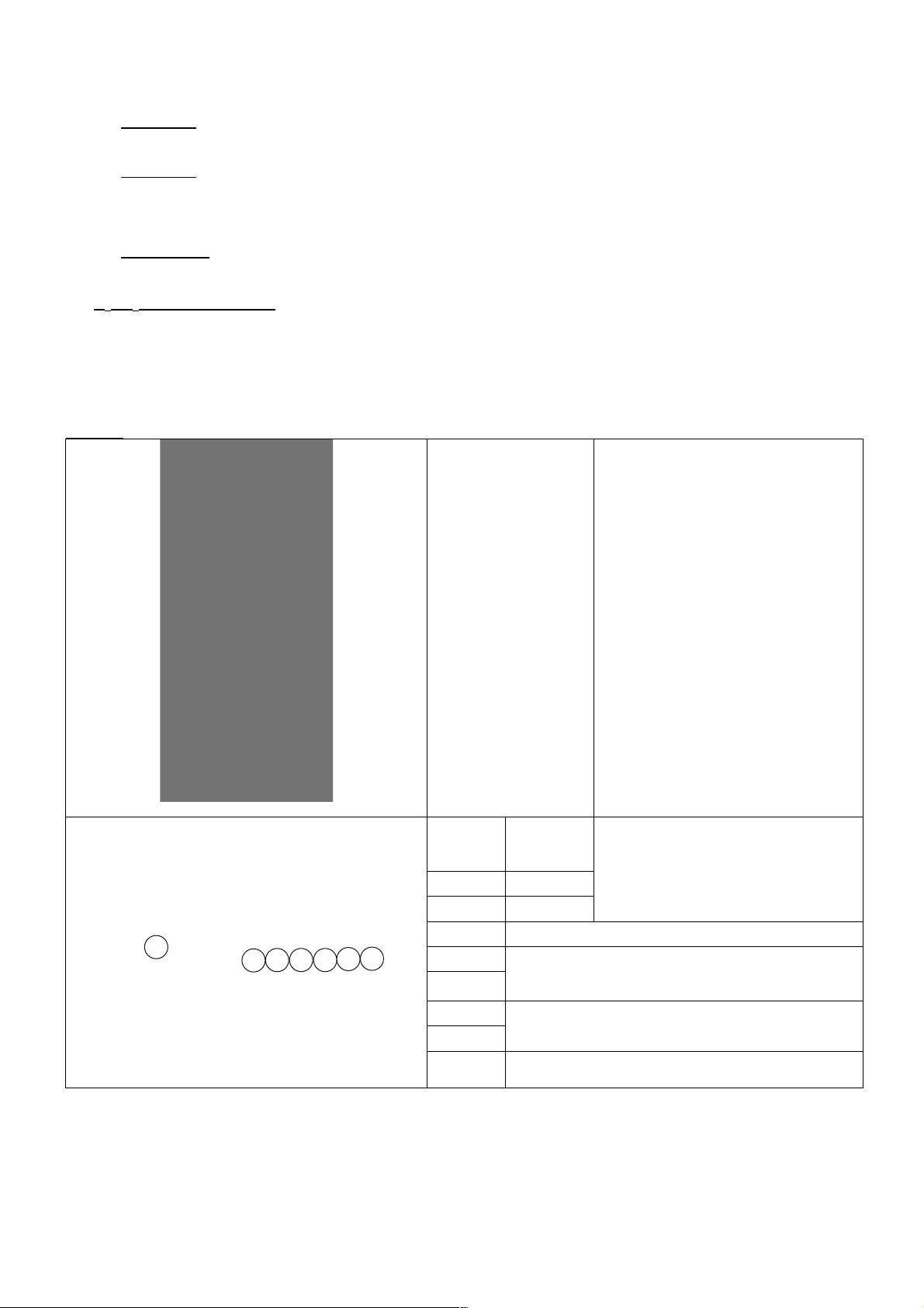
ELEKTRISCHE ANSCHLÜSSE
Eingang A = Versorgung
100 ÷ 240 Vac (50-60 Hz)
oder 24Vac/dc
Eingang B =
Spannungsfreie Impulse
(Impulszähler oder Hall-
Sensor)
Eingang C = Eingang
Füllstandskontrollsonde
Die Pumpe muss an eine Versorgung
angeschlossen werden, die mit den
Angaben auf dem Etikett an der Seite
der Pumpe übereinstimmen. Die
Nichtbeachtung dieser Vorschrift kann
zu Schäden an der Pumpe führen.
Die Pumpen wurden geplant, um
geringe Überspannungen absorbieren
zu können. Um Schäden an der Pumpe
zu vermeiden, sollte daher immer
sicher gestellt werden, dass sie keine
Energiequelle zusammen mit anderen
elektrischen Apparaten nutzt, die hohe
Spannungen erzeugen.
Die Verbindung mit der 380V-
Dreiphasenleitung darf NUR
zwischen Phase und Neutralleiter
vorgenommen werden. Die
Anschlüsse DÜRFEN NICHT
zwischen Phase und Erde erfolgen.
123 4 56
F
1
Ausgangsspannung
10 Vcc
Eingang Hall-Sensor o.ä.
(Ausgangsspannung 10 Vcc;
Maximaler Strom 5 mA)
2
Signal
4
GND
3
Nicht genutzt.
2
Spannungsfreie Impulse
(Impulszähler; Trockenkontakt: on-off,
Höchstfrequenz 80Hz)
4
5
Eingang Füllstandskontrollsonde
(Trockenkontakt:on-off)
6
F
Sicherung: 2A (100 ÷ 240 Vac) / 3,15 (24Vac/dc);
250V; T 5x20

EM00136452 Rev.1.0 DE
3
EINSTELLUNGEN DOSIERMODALITÄTEN
Im Bereich der elektrischen Anschlüsse des Schaltkreises ist ein
Schalter vorhanden (siehe Abbildung), der den Dosiermodus der
Pumpe regelt.
Die zwei verschiedenen Modi sind:
Konstant (Schalter in Position C)
Die Pumpe dosiert kontinuierlich den am Potentiometer eingestellten
Prozentsatz.
Proportional (Schalter in Position P)
Die Pumpe dosiert proportional beim Eingangssignal (Impulszähler).
HYDRAULIKANSCHLÜSSE
13
4
6
3
12
5
2
11
6
4
8
4
6
6
43
14
5
10
9
7
5
5
1
1. Einspritzpunkt
2. Anschluss Einspritzung
3. Dichtung
4. Schlauchhalterung
5. Schlauchdurchführung
6. Gewindering
7. Druckschlauch (starr)
8. Druckventil
9. Pumpengehäuse
10. Ablassventil
11. Ansaugventil
12. Ansaugschlauch (weich)
13. Bodenfilter
14. Anschluss Ablassventil
Bohrschablonen Wandbügel
Nach etwa 800 Betriebsstunden die Bolzen des Pumpengehäuses mit einem Anzugsmoment von 3 Nm anziehen.
Zum Durchführen der Wasseranschlüsse müssen folgende Hinweise beachtet werden:
- Den BODENFILTER etwa 5-10cm über dem Boden installieren, um eventuelle Ablagerungen zu vermeiden
- Die Installation unter dem Flüssigkeitsstand wird bei Pumpen mit sehr geringer Fördermenge empfohlen. Insbesondere für
die Dosierung von Produkten, die Gase entwickeln (z.B. Natriumhypochlorit, Hydrazin, Wasserstoffperoxid,...).
- Bei Schläuchen, die länger als die im Installationssatz enthaltenen sind, ist es wichtig, dass diese dieselben Maße wie die
mit der Pumpe gelieferten aufweisen. Wenn die DRUCKLEITUNG Sonnenstrahlung ausgesetzt ist, empfiehlt sich der
Einsatz eines schwarzen, UV-beständigen Schlauchs;
- Der EINSPRITZPUNKT sollte höher als die Pumpe oder der Tank liegen;
- Das EINSPRITZVENTIL, das mit der Pumpe geliefert wird, muss immer am Ende der Druckleitung des Dosierungsflusses
installiert werden.
START
Nach der Durchführung aller zuvor beschriebenen Schritte ist die Pumpe für den Start bereit.

EM00136452 Rev.1.0 DE
4
Befüllen
- Die Pumpe starten
- Den Befüllanschluss durch Drehen des Knaufs entgegen dem Uhrzeigersinn öffnen und warten, bis die Flüssigkeit aus der
angeschlossenen Leitung tritt.
- Nachdem sicher gestellt wurde, dass die Pumpe ganz gefüllt ist, kann der Anschluss wieder geschlossen werden und die
Pumpe beginnt mit der Dosierung.
PROBLEMBEHEBUNG
Störung
Mögliche Ursache
Lösung
Die Pumpe funktioniert normal, aber die
Dosierung wurde unterbrochen.
Verstopfung der Ventile
Die Ventile reinigen oder, wenn es nicht möglich ist,
die Verkrustungen zu entfernen, ersetzen
Übermäßige Ansaughöhe
Die Pumpe oder den Tank so positionieren, dass die
Ansaughöhe reduziert wird
Flüssigkeit zu viskos
Die Ansaughöhe reduzieren oder eine Pumpe mit
höherer Fördermenge nutzen
Unzureichende Fördermenge
Leckage der Ventile
Kontrollieren, ob die Gewinderinge korrekt
angezogen sind
Flüssigkeit zu viskos
Eine Pumpe mit höherer Fördermenge nutzen oder
die Ansaughöhe reduzieren
Teilweise Verstopfung der
Ventile
Die Ventile reinigen oder, wenn es nicht möglich ist,
die Verkrustungen zu entfernen, ersetzen
Unregelmäßige Fördermenge der
Pumpe
Für die Druckleitung wird
ein transparenter PVC-
Schlauch genutzt
Einen undurchsichtigen PE-Schlauch für die
Druckleitung nutzen
Membran ist kaputt
Zu hoher Gegendruck
Den Druck der Anlage prüfen. Prüfen, ob das
Einspritzventil verstopft ist. Prüfen, ob zwischen den
Druckventilen und dem Einspritzpunkt
Verstopfungen vorhanden sind.
Betrieb ohne Flüssigkeit
Prüfen, ob der Bodenfilter (das Ventil) vorhanden
ist. Eine Füllstandssonde verwendet, die die Pumpe
blockiert, wenn das chemische Produkt im Tank zu
Ende geht
Membran nicht richtig
befestigt
Bei Ersatz der Membran prüfen, dass diese wieder
richtig befestigt wird.
Die Pumpe geht nicht an
Unzureichende Versorgung
Prüfen, ob die Werte auf dem Typenschild der
Pumpe mit denen des Stromnetzes
übereinstimmen.
Bedienfeld – KOMPACT AMC
KONSTANTER MODUS (Schalter in Position C)
Die Pumpe dosiert manuell den mit dem Potentiometer gewählten Prozentsatz
Die grüne, durchgängig leuchtende LED geht bei jedem Schlag aus, die die Pumpe durchführt.
Die grüne LED blinkt, wenn das Potentiometer auf 0 steht.
PROPORTIONALER MODUS 4:1 (Schalter in Position P)
Die Pumpe führt einen Schlag durch, nachdem sie vier externe Schläge erhalten hat (Impulszähler) und das
Potentiometer auf 100% eingestellt ist.
Das Potentiometer gestattet die Erhöhung der Anzahl der erhaltenen externen Impulse, nach denen die Pumpe
einen Schlag durchführt.
Es folgt ein Betriebsbeispiel:
Potentiometer [%]
1 Schlag /
Impulse
100
4
50
8
10
40
LED Dosierung und
Alarmkontrollleuchte
Füllstandssonde.
Potentiometer Einstellung % der
Fördermenge.

EM00136452 Rev.1.0 DE
5
Die orange, durchgängig leuchtende LED geht bei jedem Schlag aus, den die Pumpe durchführt.
Die orange LED blinkt, wenn das Potentiometer auf 0 steht.
Lehre
Zähler
Qn
max vom Zähler lieferbare
Imp/min
[Qn x Imp/l]
max. Frequenz der Pumpe
[4 Imp Zähler = 1 Imp
Pumpe ]
max. dosierbare ppm
bei der max. Frequenz
5
0,69
Imp/l
l/Imp
Imp/l
l/Imp
Imp/l
l/Imp
Größe
m3/h
4
1
100
1000
4
1
100
1000
4
1
100
1000
1/2"
1,5
100
25
25
6
521
130
3/4"
2,5
167
42
42
10
521
130
1"
3,5
233
58
58
15
521
130
1"1/4
5
333
83
83
21
521
130
1"1/2
10
667
167
160
42
500
130
2"
15
1.000
250
2,5
160
63
0,63
333
130
1,3
2"1/2
25
4,2
1,04
1,3
3"
40
6,7
1,67
1,3
4"
60
10,0
2,50
1,3
6"
150
2,5
0,63
0,13
ALARME
Anzeige
Ursache
Unterbrechung
Die rote LED leuchtet durchgängig.
Alarm minimaler Füllstand erreicht
Flüssigkeit nachfüllen.

EM00136452 rev.1.0 ES
1
AB
E
C
G
I
F
D
H
MANUAL DE INSTALACIÓN Y PUESTA EN FUNCIONAMIENTO PARA
BOMBA DOSIFICADORA SERIE KOMPACT AMC
Contenido del embalaje:
A. Manguera opaca para la conexión de la salida de la
bomba hasta el punto de inyección
B. Tubo transparente para la aspiración, la conexión de
la válvula de purga y para el cebado manual.
C. Racor de inyección
D. Kit conexiones tubos
E. Filtro de fondo
F. Soporte para el montaje en pared
G. Tacos para fijar el soporte a la pared
H. Tapones protección tornillos
I. Manual de instrucciones
PARA CARACTERÍSTICAS HIDRÁULICAS ESPECÍFICAS CONSULTE LA ETIQUETA DE LA BOMBA
INTRODUCCIÓN
La bomba dosificadora está formada por un mando con los dispositivos electrónicos y un imán, así como una parte hidráulica
que siempre está en contacto con el líquido que se va a dosificar.
Controle en la placa los datos con las características principales de la bomba
1. Área regulaciones
2. Cabezal dosificador
3. Válvula de cebado
4. Racor de impulsión
5. Racor de aspiración
6. Soporte de montaje (opcional)
Se recomienda una revisión de la compatibilidad química entre el producto dosificado y los materiales en
contacto.
MATERIALES QUE FORMAN PARTE DEL CABEZAL DE LA BOMBA
• Cuerpo bomba: PVDF-T
• Válvulas: PVDF-T
• Esferas: Cerámica
• Membrana: PTFE
CARACTERÍSTICAS TÉCNICAS
• Peso: 1,5 Kg
• Alimentación: 100 ÷ 240 Vac (50-60 Hz) – 24Vac/dc
• Consumo: 13W @ 100 Vac – 19W @ 240 Vac – 12W @ 24 Vac/dc
• Fusible: 2A (100 ÷ 240 Vac) / 3,15 (24V); 250V; T 5x20
• Grado de protección IP65
• Entrada control nivel: Contacto seco (on-off)
• Entrada impulsos: Contacto seco (on-off) frecuencia máxima 80Hz

EM00136452 rev.1.0 ES
2
LEA ATENTAMENTE ANTES DE REALIZAR LA INSTALACIÓN
O CUALQUIER OPERACIÓN DE MANTENIMIENTO EN LA BOMBA.
I
ATENCIÓN: ANTES DE REALIZAR LA INSTALACIÓN O EL MANTENIMIENTO DE LA BOMBA,
DESCONECTE LA CORRIENTE ELÉCTRICA.
I
ATENCIÓN: RECOMENDAMOS LA INSTALACIÓN DE LA BOMBA EN POSICIÓN VERTICAL PARA
GARANTIZAR EL CORRECTO FUNCIONAMIENTO.
I
ATENCIÓN: PRODUCTO DE USO PROFESIONAL, OPERADO SOLAMENTE POR PERSONAL
CALIFICADO.
I
ATENCIÓN: EL MANTENIMIENTO DE LA BOMBA MUST SOLO DEBE SER EFECTUADO POR
PERSONAL CALIFICADO Y AUTORIZADO.
- H2SO4 ACIDO SULFURICO Antes de dosificar los productos que puedan reaccionar con el agua, es necesario secar
todas las partes internas de la hidráulica.
- Temperatura ambiente menor a 40°C. Humedad relativa menor a 90%. Grado de protección IP65 No instale la bomba
donde quede expuesta directamente a los rayos solares.
- Asegure la bomba para evitar vibraciones excesivas.
- La tensión de alimentación y la presión en el sistema deben ser compatibles con lo descrito en la placa de la bomba.
CONEXIONES ELÉCTRICAS
Entrada A =
Alimentación 100 ÷
240 Vac (50-60 Hz) o
24Vac/dc
Entrada B =
Impulsos de voltaje
libres
(contador lanza-
impulsos o sensor
hall)
Entrada C = Entrada
sonda de control nivel
La bomba debe conectarse a una
línea eléctrica que sea conforme con
la que figura en la etiqueta de la
bomba. El incumplimiento de estas
instrucciones puede causar daños a
la bomba.
Las bombas están diseñadas para
absorber pequeñas sobre tensiones.
Por lo tanto, para evitar daños en la
bomba es conveniente asegurarse
que la bomba no tenga ninguna
fuente de energía compartida con los
aparatos eléctricos que generan
altos voltajes.
La conexión a la línea trifásica de
380V sólo debe realizarse entre
fase y neutro. La conexión NO
DEBE efectuarse entre fase y
tierra.
123 4 56
F
1
Tensión
de salida
10 Vcc
Entrada sensor hall o similar
(tensión de salida 10 Vcc; corriente
máxima 5 mA)
2
Señal
4
GND
3
No usado.
2
Impulsos de voltaje libres
(contador lanza-impulsos; contacto seco: on-off,
frecuencia máxima 80Hz)
4
5
Entrada sonda de control del nivel
(Contacto seco: on-off)
6
F
Fusible: 2A (100 ÷ 240 Vac) / 3,15 (24V); 250V; T
5x20

EM00136452 rev.1.0 ES
3
PROGRAMACIONES MODO DE DOSIFICACIÓN
En las conexiones eléctricas del circuito, hay un interruptor (que se
muestra en la figura), que regula la bomba dosificadora.
Los modos son:
Constante (switch en posición C)
La bomba dosifica en forma permanente de acuerdo con el porcentaje
seleccionado con el potenciómetro.
Proporcional (switch en posición P)
La bomba dosifica en forma proporcional a la señal de entrada (Contador
lanza-impulsos).
CONEXIONES HIDRÁULICAS
13
4
6
3
12
5
2
11
6
4
8
4
6
6
43
14
5
10
9
7
5
5
1
1. Punto de inyección
2. Racor de inyección
3. Estanqueidad
4. Porta-tubo
5. Prensa tubo
6. Abrazadera
7. Tubo impulsión (rígido)
8. Válvula de impulsión
9. Cuerpo bomba
10. Válvula de purga
11. Válvula de aspiración
12. Tubo de aspiración (blando)
13. Filtro de fondo
14. Racor válvula de purga
Dime de perforación del soporte de pared
Transcurridas unas 800 horas de trabajo, apretar los tornillos del cuerpo bomba aplicando un par de apriete de 3 Nm.
Al hacer las conexiones hidráulicas debe seguir las siguientes instrucciones:
- Instalar el FILTRO DE FONDO a unos 5-10cm del fondo para evitar que se obstruya por los depósitos;
- LA instalación con bomba a la altura de aspiración se recomienda en bombas con caudal bajo. En particular, cuando se
dosifican productos que crean gases (por ejemplo, hipoclorito de sodio, la hidracina, el peróxido de hidrógeno, ...).
- Los tubos de longitud superior a los del Kit de instalación es importante que sean del mismo tamaño que los suministrados
con la bomba. Si el TUBO DE IMPULSIÓN se expone a los rayos solares se recomienda uTilizar tubo negro resistente a
los rayos ultravioleta;
- El PUNTO DE INYECCIÓN debe colocarse más alto que la bomba o el tanque;
- La VÁLVULA DE INYECCIÓN que se suministra con la bomba, se debe instalar siempre en el extremo de la línea de
impulsión del flujo de dosificación.
PUESTA EN MARCHA
Una vez que haya comprobado todos los pasos anteriores, la bomba ya está lista para arrancar.

EM00136452 rev.1.0 ES
4
Cebado
- Poner en marcha la bomba
- Abra el racor de cebado girando la perilla en sentido antihorario y esperar que el líquido salga desde el tubo conectado a
él.
- Una vez que esté seguro de que la bomba está completamente llena de líquido puede cerrar la conexión y la bomba
comienza a dosificar.
SOLUCIÓN DE PROBLEMAS
Avería
Causa posible
Solución
La bomba está funcionando con
normalidad, pero la dosificación se
interrumpe.
Obstrucción de la válvulas
Limpie o reemplace las válvulas si no se puede
remover el sucio
Altura de aspiración
excesiva
Coloque la bomba o el tanque con el fin de reducir
la altura de aspiración
Líquido muy viscoso
Reducir la altura de aspiración o utilizar bomba con
mayor caudal
Caudal insuficiente
Fugas en las válvulas
Compruebe el apriete de las abrazaderas
Líquido muy viscoso
Utilice bomba con mayor caudal o disminuya la
altura de aspiración
Obstrucción parcial de la
válvulas
Limpie o reemplace las válvulas si no se puede
remover el sucio
Caudal de la bomba irregular
Tubo PVC transparente en
la impulsión
Utilice tubo PE opaca en la impulsión
Rotura de la membrana
Contrapresión excesiva
Controlar la presión del sistema Comprobar que la
válvula de inyección no esté obstruida. Comprobar
que no exista obstrucción entre las válvulas de
impulsión y el punto de inyección.
Funcionamiento sin líquido
Comprobar la presencia del filtro (válvula) de fondo.
Utilice una sonda de nivel para bloquear la bomba
cuando en el tanque se acaba el producto químico.
La membrana no está
fijada correctamente
Si la membrana ha sido reemplazada comprobar
que se haya ajustado correctamente.
La bomba no se enciende
Corriente eléctrica
insuficiente
Comprobar que los valores que figuran en la placa
de la bomba correspondan con los de la red
eléctrica.
Panel de control – KOMPACT AMC
MODO CONSTANTE (switch en posición C)
La bomba dosifica el porcentaje seleccionado de forma manual con el potenciómetro.
El led verde fijo se apaga con cada golpe que la bomba efectúa.
Led verde parpadeante con el potenciómetro en 0.
MODO PROPORCIONAL 4:1 (switch en posición P)
Con el potenciómetro al 100% y después de recibir cuatro impulsos (contador lanza impulsos), la bomba efectúa
un golpe.
El potenciómetro está diseñado para aumentar el número de impulsos externos recibidos, después de los cuales
la bomba realiza un golpe.
Estos son algunos ejemplos de funcionamiento:
Potenciómetro [%]
1 golpe /
Impulsos
100
4
50
8
10
40
El led naranja fijo se apaga con cada golpe que la bomba efectúa.
Led naranja parpadeante con el potenciómetro en 0.
Led dosificación e indicador
luminoso alarma sonda de
nivel.
Potenciómetro regulación % del
caudal

EM00136452 rev.1.0 ES
5
calibre
contador
Qn
máx imp/min del contador
[Qn x imp/l]
frecuencia máx de la
bomba
[4 imp contador = 1 imp
bomba]
máx ppm dosificables
con la frecuencia máx
5
0,69
imp/l
l/imp
imp/l
l/imp
imp/l
l/imp
tamaño
m3/h
4
1
100
1000
4
1
100
1000
4
1
100
1000
1/2"
1,5
100
25
25
6
521
130
3/4"
2,5
167
42
42
10
521
130
1"
3,5
233
58
58
15
521
130
1"1/4
5
333
83
83
21
521
130
1"1/2
10
667
167
160
42
500
130
2"
15
1.000
250
2,5
160
63
0,63
333
130
1,3
2"1/2
25
4,2
1,04
1,3
3"
40
6,7
1,67
1,3
4"
60
10,0
2,50
1,3
6"
150
2,5
0,63
0,13
ALARMAS
Visualización
Causa
Interrupción
Encendido led de color rojo fijo.
Alarma terminación nivel
Restablecer el nivel del líquido.

EM00136452rév.1.0 FR
1
AB
E
C
G
I
F
D
H
MANUEL INSTALLATION ET MISE EN SERVICE POUR POMPE DOSEUSE
SÉRIE KOMPACT AMC
Contenu de l'emballage :
A. Tube opaque pour le raccordement de la sortie de la
pompe au point d'injection
B. Tube transparent pour l'aspiration, pour le
raccordement de la valve de purge et pour l'amorçage
manuel
C. Raccord d'injection
D. Kit raccordements tubes
E. Filtre de fond
F. Étrier pour montage mural
G. Chevilles pour la fixation de l'étrier au mur
H. Bouchons protection vis
I. Manuel d'instructions
POUR CARACTÉRISTIQUES HYDRAULIQUES SPÉCIFIQUES VOIR LE LABEL SUR LA POMPE
INTRODUCTION
La pompe doseuse est composée d'un dispositif de commande qui loge l'électronique et l'aimant et d'une partie hydraulique
toujours en contact avec le liquide à doser.
Vérifier les principales caractéristiques de votre pompe sur les données indiquées
sur la plaque.
1. Zone de réglages
2. Tête doseuse
3. Clapet d'amorçage
4. Raccord de refoulement
5. Raccord d'aspiration
6. Support pour base (en option)
Nous conseillons de vérifier la compatibilité chimique entre le produit dosé et les matériaux en contact.
MATÉRIAUX QUI COMPOSENT LA TÊTE DE LA POMPE
• Boîtier pompe : PVDF-T
• Vannes : PVDF-T
• Billes de clapet : Céramique
• Membrane : PTFE
CARACTÉRISTIQUES TECHNIQUES
• Poids : 1,5 Kg
• Alimentation : 100 ÷ 240 Vac (50-60 Hz) - 24Vac/dc
• Absorption : 13W @ 100 Vac – 19W @ 240 Vac – 12W @ 24 Vac/dc
• Fusible : 2A (100 ÷ 240 Vac) / 3,15 (24V); 250V; T 5x20
• Degré de protection : IP65
• Entrée contrôle niveau : Contact sec (on-off)
• Entrée impulsions : Contact sec (on-off) fréquence maximum 80Hz

EM00136452rév.1.0 FR
2
LIRE ATTENTIVEMENT AVANT DE PROCÉDER À L'INSTALLATION
OU AVANT L'ENTRETIEN DE LA POMPE.
I
ATTENTION : AVANT DE PROCÉDER À L'INSTALLATION OU À L'ENTRETIEN DE LA POMPE,
TOUJOURS DÉBRANCHER L'ALIMENTATION.
I
ATTENTION : NOUS RECOMMANDONS L'INSTALLATION DE LA POMPE EN POSITION VERTICALE
AFIN D'ASSURER LE BON FONCTIONNEMENT DE CETTE DERNIÈRE.
I
ATTENTION : PRODUIT DESTINÉ UNIQUEMENT À UN USAGE PROFESSIONEL, À DU PERSONNEL
QUALIFIÉ.
I
ATTENTION : L'ENTRETIEN DE LA POMPE MUST DOIT ÊTRE EFFECTUÉ UNIQUEMENT PAR DU
PERSONNEL QUALIFIÉ ET AUTORISÉ.
- H2SO4 ACIDE SULPHURIQUE Avant de doser des produits chimiques qui peuvent réagir à l'eau il est nécessaire de
sécher toutes les parties hydrauliques internes.
- Température ambiante inférieure à 40°C. Humidité relative inférieure à 90%. Degré de protection IP65. Éviter d'installer la
pompe avec un exposition directe aux rayons solaires.
- Fixer solidement la pompe afin d'éviter des vibrations excessives.
- La tension d'alimentation et la pression sur l'installation doivent être compatibles avec les données indiquées sur l'étiquette
de la pompe.
BRANCHEMENTS ELECTRIQUES
Entrée A =
Alimentation 100 ÷
240 Vac (50-60 Hz)
ou 24Vac/dc
Entrée B =
Impulsions tension
libre (compteur
d'impulsions ou
capteur hall)
Entrée C = Entrée
sonde contrôle niveau
La pompe doit être branchée à une
alimentation conforme à celle
indiquée sur l'étiquette sur le côté de
la pompe. Le non respect de ces
indications peut provoquer des
dommages à la pompe.
Les pompes ont été conçues pour
absorber de petites surtensions. Afin
d'éviter que la pompe ne subisse de
dommages, il est conseillé de
toujours s'assurer que la pompe ne
partage pas de source d'énergie
avec les appareils électriques qui
génèrent des tensions élevées.
La connexion avec la ligne
triphasée 380V DOIT être effectuée
seulement entre phase et neutre.
La connexion NE DOIT pas être
effectuée entre phase et terre.
123 4 56
F
1
Tension de
sortie 10
Vcc
Entrée capteur hall ou similaire
(tension de sortie 10 Vcc ; courant
maximum 5 mA)
2
Signal
4
GND
3
Non utilisé.
2
Impulsions tension libre
(compteur d'impulsions ; contact sec : on-off,
fréquence maximum 80Hz)
4
5
Entrée sonde contrôle niveau
(Contact sec : on-off)
6
F
Fusible : 2A (100 ÷ 240 Vac) / 3,15 (24V); 250V; T
5x20

EM00136452rév.1.0 FR
3
CONFIGURATIONS MODALITE DOSAGE
Un interrupteur (indiqué sur la figure) qui règle les modalités de dosage de
la pompe est présent sur la partie correspondant aux branchements
électriques du circuit.
Les deux modalités différentes sont :
Constante (interrupteur sur la position C)
La pompe dose constamment au pourcentage sélectionné avec le
potentiomètre.
Proportionnelle (interrupteur sur la position P)
La pompe dose proportionnellement au signal d'entrée (Compteur
d'impulsions).
BRANCHEMENTS HYDRAULIQUES
13
4
6
3
12
5
2
11
6
4
8
4
6
6
43
14
5
10
9
7
5
5
1
1. Point d'injection
2. Raccord d'injection
3. Étanchéité
4. Porte-tuyau
5. Presse-tube
6. Bague
7. Tube de refoulement (rigide)
8. Clapet de refoulement
9. Boîtier pompe
10. Valve de purge
11. Clapet d'aspiration
12. Tube d'aspiration (souple)
13. Filtre de fond
14. Raccord valve de purge
Gabarits perçage étrier mural
Après environ 800 heures de fonctionnement, serrer les boulons du boîtier de pompe en appliquant un couple de serrage de 3
Nm.
Suivre les instructions suivantes lors des branchements hydrauliques :
- Installer le FILTRE DE FOND à environ 5-10 cm du fond de façon à éviter des dépôts éventuels ;
- L’installation avec pompe sous charge d'eau est recommandée pour des pompes ayant un débit très faible. En particulier
en cas de dosage de produits qui développent du gaz (par ex: hypochlorite de soude, hydrazine, peroxyde d'hydrogène...).
- Tubes plus longs que ceux du kit d'installation, il est important qu'ils aient la même dimension que ceux fournis avec la
pompe. Si le TUBE DE REFOULEMENT est exposé aux rayons solaires on conseille l’utilisation d'un tube noir résistant
aux rayons ultraviolets ;
- On conseille de placer le POINT D'INJECTION plus haut que la pompe ou que le réservoir ;
- Le CLAPET D'INJECTION fourni avec la pompe doit toujours être installé au bout de la ligne de refoulement du flux de
dosage.
Table of contents
Languages:
Popular Water Pump manuals by other brands

Etatron
Etatron eSelect M 1 CI Operating instructions and maintenance

Xylem
Xylem Bell & Gossett VSX Series instruction manual

Little Giant
Little Giant 5-ASP-FS instruction manual

Checkpoint
Checkpoint ATP Series operating manual

Graco
Graco Husky 3300e Operation

Grundfos
Grundfos ALPHA1 L Installation and operating instructions

Graco
Graco Merkur Bellows Instructions - parts

EasyPro
EasyPro EX3600 Installation and service manual

GORMAN-RUPP PUMPS
GORMAN-RUPP PUMPS RP4D60 Installation, operation, and maintenance manual with parts list

salmson
salmson MULTI-V 1 Installation and starting instructions

Wayne
Wayne PC4 Operating instructions and parts manual

Aqua Flo
Aqua Flo Flo-Master HP Series owner's manual