Korea Network Corporation MyNetGate 1000 User manual

1
Korea Network Corporation
DOCSIS Cable Modem MyNetGate 1000
USER’S MANUAL
Copyright
@
2000
Korea Network Corporation
.
All
rights
reserved.
This
users
guide
may
not
be
reproduced,
in
part
or
in
whole,
without
the
permission
of
Korea Network Corporation
.
The
content
of
this
users
guide
is
subject
to
change
without
notice
in
the
future.
Korea Network Corporation
assumes
no
liability
for
damages
resulting
from
the
use
of
this
product
or
the
information
contained
in
this
users
guide
Trademarks
Microsoft,
Windows95,
98
and
windows
NT
are
registered
trademarks
of
Microsoft
Corporation.
MyNetGate
is
trademarks
of
Korea Network Corporation
.
All
other
trademarks
and
registered
trademarks
are
the
property
of
their
respective
owners.
Revision
01
June
2000

2
Korea Network Corporation
1. Safety Precautions
Please do not damage the DC power adaptor or plug.
Please do not connect the cable connector at the back of the cable modem to the TV antenna
cable. Only connect to the CATV network providing the cable Internet service.
The cable modem should be located on a safe, flat surface in a space with plenty of ventilation.
Please do not place electronic equipment or other objects on the top of the cable modem.
Korea Network Corporation
will not be responsible for damage incurred by user mishandling or
misuse, or opening of the product case.
2. Box Contents
Please verify that the cable modem box contains the following.
Fig
1.
MNG-1000 Box Contents
2.1 Other Requirements
The cable modem requires a user PC running
Windows
95/98/NT/2000 supporting TCP/IP,
DHCP/BOOTPprotocols
The user PC needs to have an Ethernet
10/100
Base-T
LAN card installed. The LAN card
maybe be purchased by the user or supplied by the Internet Service Provider.
Note : Please record the serial number and MAC address printed at the bottom of the cable
modem on the front page of the manual. This information will be required to place an A/S
request.
MNG-1000
DC adaptor
Ethernet Cable
Manual

3
Korea Network Corporation
3. MNG-1000 Cable Modem LED’s
The front of the MNG-1000cablemodeminclude fiveLED’s that are marked POWER,
STATUS,
TX,
RX and
PC. These are used in indicating the operating status of the cable modem.
Fig 2.MNG-1000 Front View
3.1 POWER LED
When the DC adaptor plug is connected and power applied to the MNG-1000 cable modem, all
five LED’s will light up briefly before the POWER led lights up for 1 seconds then starts to flash.
This indicates that power has been correctly applied to the modem.
During the time that the POWER led is flashing, the cable modem copies its operating program
from the flash memory to the DRAM memory. After around 10~13 flashes, the LED will remain
constantly on as long as power is applied.
3.2 STATUS LED
The STATUS led remains flashing while the modem is being initialized. After initialization is complete
and normal operation is possible, the STATUS led remains green. The STATUS led needs to remain
green in order for the Internet access to work properly.
However, if the cable modem is unable to acquire its IP address from the server through DHCP, the
STATUS led will flash red. If the modem is unable to acquire its configuration setting from the server
through TFTP, the STATUS led will flash orange. In both cases, please contact the customer service
center of your ISP.
After power is applied to the cable modem and its operating program is copied to DRAM, the modem
searches for the downstream channel.
3.3 RX LED
After the MNG-1000 cable modem as found the downstream channel, the RX led will turn green.
During the time that data traffic is flowing through this downstream channel, the RX will begin
flashing.
3.4 TX LED
POWER STATUS TX PCRX

4
Korea Network Corporation
The MNG-1000 cable modem acquires upstream channel information from the downstream channel and
performs ranging in order to transmit data on the upstream channel properly. The TX led will turn green
following completion of ranging and the modem is now ready transmit data. When transmit is in progress, the
TX led will flash. If the upstream channel is lost, the TX led will turn off.
3.5 PC LED
The PC led indicates the status of the link between the MNG-1000 cable modem and computer.
If the cable modem and computer is connected via the Ethernet cable, the PC led will turn green.
Whendatatrafficbetween the cable modem and computer is active,the PC led will flash green. If the
cable modem and computer is not properly connected, the PC LED will remain off. In this case,
please check the Ethernet cable or the Ethernet card inside the computer.
TABLE 1. LED STATE SUMMARY
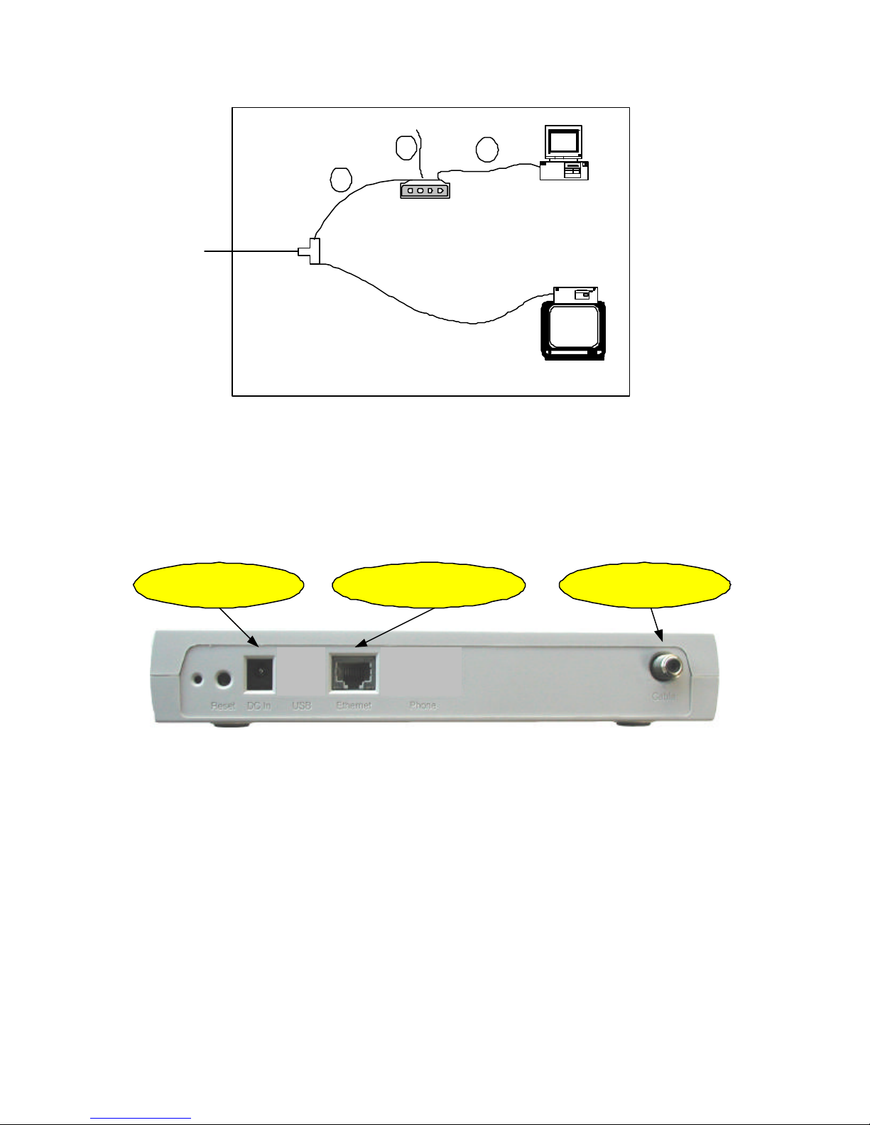
4. MNG-1000 Cable Modem Rear
LED Name Function Color Display
POWER Power and program install Green OFF: No power
FLASH:Booting and self test
ON: Power applied
STATUS
Modem and software
initialization status
Green
Red
Orange
OFF: No power
FLASH: Normal progress
ON: Normal state
FLASH: IP address acquired fail
DHCP retry
FLASH: Config file acquire fail
TFTP retry
TX Cable port transmit status Green OFF: No upstream channel
FLASH: Upstream data transfer
ON: Upstream channel sync
RX Cable port receive status Green OFF: No downstream channel
FLASH: Downstream data transfer
ON: Downstream channel sync
PC Ethernet transmit/receivestatus Green OFF: Ethernet cable un-connected
FLASH: Data Tx/Rx in progress
ON: Ethernet link OK

5
Korea Network Corporation
The rear of the cable modem includes various connectors and switches. Some of the
connectors have been included to provide for additional functionality in the future and are not
currently being used.
Fig 3. Cable Modem Rear View
4.1 Factory Switch
The factory switch enables the modem to return the modem to the original settings used for
factory production. This will enable the cable modem to recover from any problems. The cable
modem will then automatically acquire and make settings, which are then stored within the cable
modem. However, it may take a long time to make these settings and store them.
The factory switch should never be used at owner’s discretion. If there are any problems,
please first contact the ISP customer service center.
4.2 Reset Switch
The reset switch is used to reset the cable modem. Pressing the reset switch has the same
effect as unplugging and reapplying the DC power supply.
4.3 DC in Connector
This connector is used to supply the DC power to the cable modem and is connected to the plug
from the 7.5V DC adaptor. The modem will undergo the initialization routine described in chapter 3
upon power on.
Please do not use a DC power adaptor other than that included in the original box. Using an
unknown adaptor may cause a serious damage to the cable modem.
4.4 USB Jack
Factory
DC in
Reset
Cable
Ethernet

6
Korea Network Corporation
Currently Ethernet is used to connect the cable modem to the computer but in the future, USB
may be used instead. The current MNG-1000 operating program does not support USB by default.
The program supporting USB will be released in the near future and available for upgrade on the
current modem. In this case, the computer will not require the LAN card but it will need a software
driver, which will be provided on a floppy disk.
4.5 Ethernet Jack
The MNG-1000 cable modem and computer can be linked using theEthernet cable included in
the box. This cable is a “direct”connected cable.
There are two types ofEthernet cables, “direct”and “cross”. The“cross”type cable can be used
to connect the modem and hub. The diagram below is a enlargement of the Ethernet connectors.
FIG.
4
Ethernet
Cable Wiring Diagram
4.6 Phone Port
The MNG-1000 cable modem includes two connectors labeled “Phone”. These ports will be used to
support VoIP telephony in the future. Currently, the ports are used by developing engineers and installation
people and should not be used by users.
4.7 Cable Connector
The cable connector is used to connect the RF coaxial cable from the CATV network to the
modem. The cable modem is connected to the ISP via this connector.
5. Cable Modem Installation
Direct Cross

7
Korea Network Corporation
Fig. 5 Installation Setup
Thefigure below showsthe rear ofthe MNG-1000 cable modem. The cable modem installation
can be setup as shown in figure 5.
Fig.
6
MNG-1000 Cable Modem Rear
Connect the RF cable inside the home or office to the Cable connector.
Usethe Ethernet cable included inside the box to connect the modem to the computer. The computer
must have a LAN installed with theproper LAN card driver installed on
Windows
95/98/NT/2000
Lastly, power up the modem by connecting the DC adaptor plug into the “DC in”jack of the modem.
You will be able to use your Internet within around 1.5 minuites.
6. Cable Modem Inspection
PC
Cable Modem
CATV Converter
Cable Splitter
1
2
3
3. DC Adaptor
2. Ethernet Cable
1. CATV
Cable

8
Korea Network Corporation
In order to verify proper operation of the cable modem, the user must first inspect the LED status and
thenverify that the computer as acquired IP correctly. The LED status is detailed in chapter 3.
6.1 Computer IP Address Verification
Following proper operation of the cable modem based on LED indicators, the status of the
modem can be verified from the computer side as follows. From the desktop, select
[start]=>[run] and type “winipcfg”inside the popup window before clicking OK.
From the IP Configuration popup window, select the correct Ethernet Adaptor.
If the Ethernet adaptor’s IP is [0.0.0.0]
or
[169.X.X.X], the IP needs to be re-assigned for
proper Internet access. First, click [Release All] to release all previously assigned IP’s. The
IP Address should show either [0.0.0.0]
or
[169.X.X.X]. A new IP address will be assigned
after [Renew All] button is clicked.
If the IP does not change from [0.0.0.0]
or
[169.X.X.X]
after the above procedure #3, there

9
Korea Network Corporation
are three possible reasons. Firstly, the cable modem may not be operating properly.
Secondly, LAN card may not be installed properly and thirdly, the server may be down.
In order to make sure that the cable modem may be the reason, it may be useful to unplug and then
re-connect the DC power from the modem and let it initialize again.
If the IP address is still not correct, select the menu [Start]=>[Settings]=>[Control
Panel]=>[System]=>[Device Manager]=>[Network Adaptors] and make sure that there is no
(!) in front of the LAN card. The (!) mark shows that the LAN card is not installed properly. In
this case, please try re-installing the LAN card after referring to the LAN card user’s manual.
Ifthe IP address still cannotbeacquired after procedures 5&6, please contact the customer
service center of your ISP.
7. Check Points for Modem Problems
Please verify proper Ethernet connection between the modem and the computer.
Please verify that the RF cable is properly connected to the cable modem.
Please verify proper installation of the computer OS, TCP/IP protocol and LAN card.
Please verifythat the cable modem information(MAC address) is properly registered with the
ISP.

10
Korea Network Corporation
Ifthe problem remains unresolved, pleasereferto this manual againorcontact the purchase
company or store.
8. Contact Information
Sales Contact
E-mail: hnyoun@knc.co.kr, [email protected]
Web Page : www.knc.co.kr
9. US FCC Class B Notice
Federal communications Commission(FCC) Statements
This device complies with Part 15 of the FCC Rules. Operation is subject to the following
two conditions: (1) this device may not cause harmful interference, and (2) this device

11
Korea Network Corporation
must accept any interference received, including interference that may cause undesired
operations.
Radio Frequency Interference Statement
Note: this equipment has been tested and found to comply with the limits for a Class
B digital device, pursuant to part 15 of the FCC Rules. These limits are designed
to provide reasonable protection against harmful interference in a residential
installation. This equipment generates, uses and can radiate radio frequency energy and,
if not installed and used in accordance with the instructions, may cause harmful
interference to radio communications. However, there is no guarantee that interference
will not occur in a particular installation. If this equipment does cause harmful
interference to radio or television reception, which can be determined by turning
the equipment off and on, the user is encouraged to try to correct the interference by
one more of the following measures:
Reorient or relocate the receiving antenna.
Increase the separation between the equipment and receiver.
Connect the equipment into an outlet on a circuit different from that to which
the receiver is connected.
Consult the dealer or an experienced radio/TV technician for help.
This manual suits for next models
1
Table of contents
Popular Modem manuals by other brands

Verizon Wireless
Verizon Wireless AD3701 Product user manual

Edgewater Networks
Edgewater Networks EdgeMarc 250AE Hardware installation guide

Franklin Wireless
Franklin Wireless 3Gstick U210 user manual

iNetVu
iNetVu UHP-1000 quick start guide

comwave
comwave SR35ON installation guide

NetComm
NetComm Mega-i-Modem 56 quick start guide