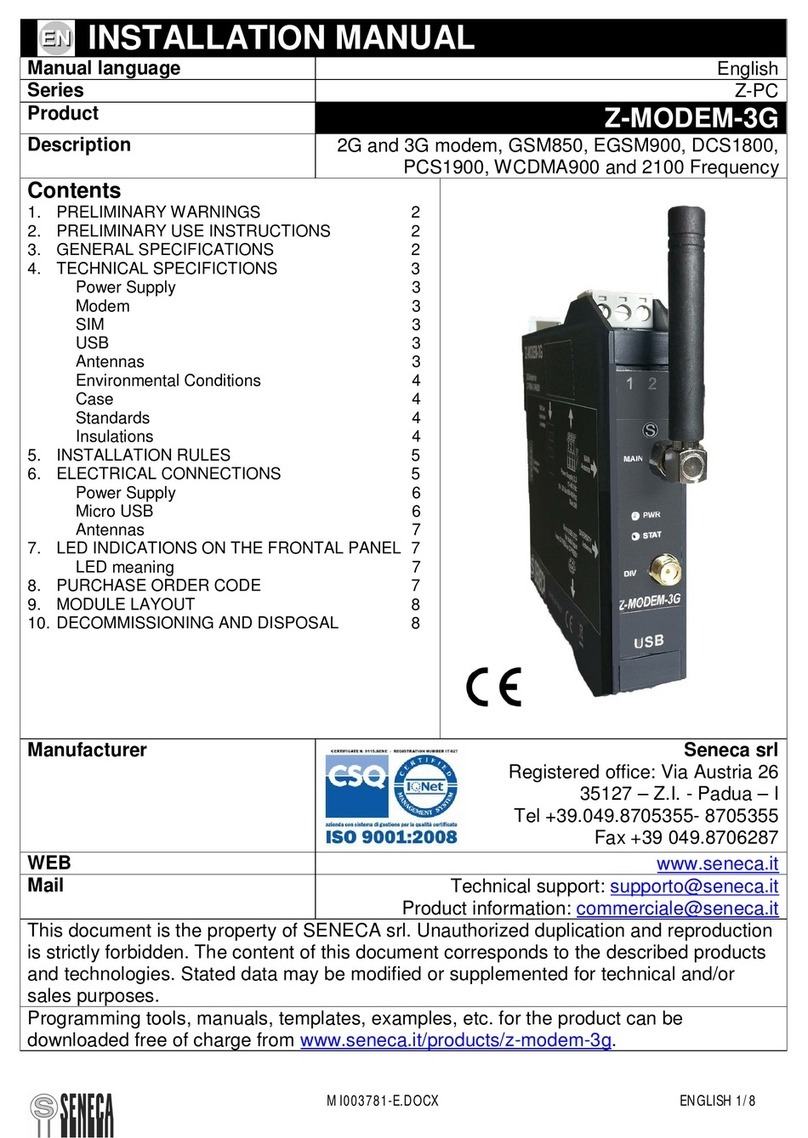
Bivocom TW810-B5 User manual

Addr.: Unit 704, No. A3 Building, Tel: +86-592-6211770
3rd Software Park, Xiamen, China 361000 Fax: +86-592-6211727
www.bivocom.com [email protected]
1
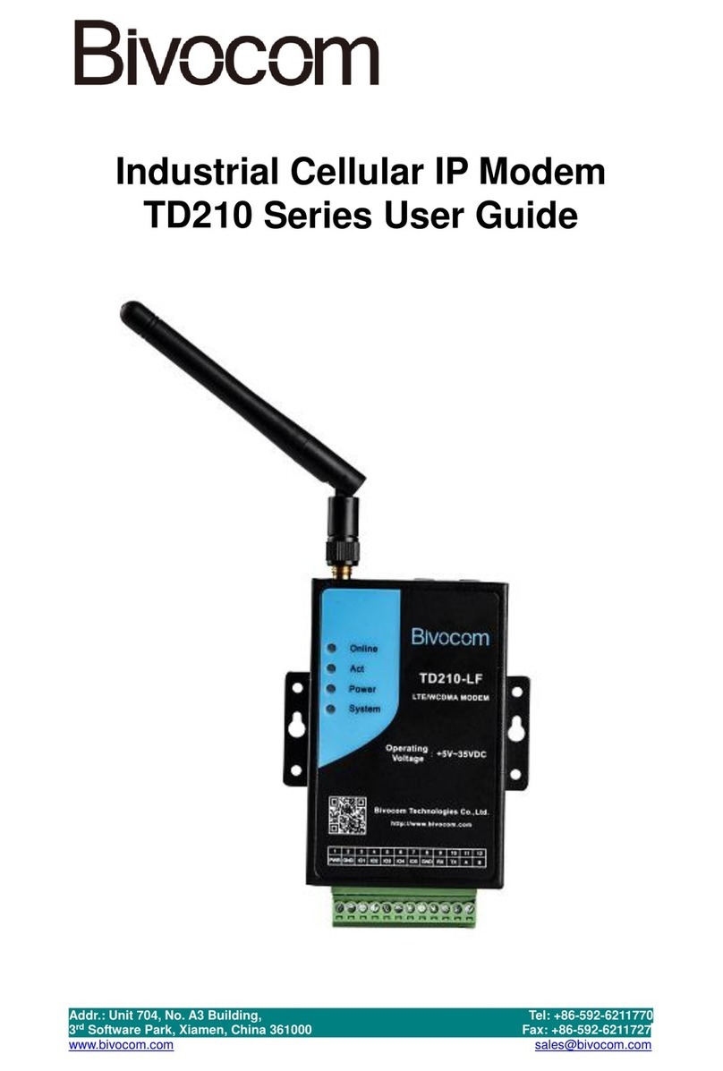
Industrial NB-IoT Cellular Modem
TW810 Series User Guide

Addr.: Unit 704, No. A3 Building, Tel: +86-592-6211770
3rd Software Park, Xiamen, China 361000 Fax: +86-592-6211727
www.bivocom.com [email protected]
2
Copyright
Copyright © XIAMEN BIVOCOM TECHNOLOGIES CO., LTD. All rights reserved.
Trademark
BIVOCOM logo is a registered trademark of Xiamen Bivocom Technologies Co., Ltd. All
other trademarks belong to their respective vendors or manufactures.
Disclaimer
Product specifications and information in this document are subject to change without any
notice, and BIVOCOM reserves the right to improve and change this user guide at any
time. Users should take full responsibility for their application of products, and Xiamen
Bivocom Technologies Co., Ltd. disclaims all warranties and liability for the accurateness,
completeness of the information published.
Global Technical &Sales Support
Xiamen Bivocom Technologies Co., Ltd.
Addr.: Unit 704, No.A3 Building, 3rd Software Park,
Xiamen, China 361000
Tel.: +86-592‐6211770
Fax: +86-592‐6211727
Email: support@bivocom.com
sales@bivocom.com
www.bivocom.com

Addr.: Unit 704, No. A3 Building, Tel: +86-592-6211770
3rd Software Park, Xiamen, China 361000 Fax: +86-592-6211727
www.bivocom.com [email protected]
3
About This Guide
Thank you for choosing BIVOCOM Industrial Cellular NB-IoT Modem TW810 Series.
Please thoroughly read this user guide before you configure and install the device.
This manual is compatible with below models
Model
Description
TW810-B5
Industrial NB-IoT Modem(850MHz)
TW810-B8
Industrial NB-IoT Modem(900MHz)
TW810-B20
Industrial NB-IoT Modem(800MHz)
Summary of Changes
Date
Version
Notes
Editor
10-01-2017
V1.0
Initial new version
Wei Liu

Addr.: Unit 704, No. A3 Building, Tel: +86-592-6211770
3rd Software Park, Xiamen, China 361000 Fax: +86-592-6211727
www.bivocom.com [email protected]
4
Table of Contents
Copyright............................................................................................................ 2
Trademark.......................................................................................................... 2
Disclaimer .......................................................................................................... 2
Global Technical &Sales Support........................................................................ 2
About This Guide................................................................................................ 3
Summary of Changes......................................................................................... 3
Table of Contents................................................................................................ 4
1. Definitions.................................................................................................... 6
2. Introduction.................................................................................................. 6
2.1 Overview................................................................................................ 6
2.2 Applications............................................................................................ 6
3. Getting Started............................................................................................. 7
3.1 Package Checklist ................................................................................. 7
3.2 Dimensions............................................................................................ 8
3.3 Installation.............................................................................................. 8
3.3.1 SIM/UIM Card .............................................................................. 9
3.2.2 Cellular Antenna........................................................................... 9
3.2.3 Terminal Block, Power Cable and Console Cable......................... 9
3.3 Power Supply....................................................................................... 10
3.4 LED Indicators......................................................................................11
4. Serial Port Configuration.............................................................................11
4.1 Operations........................................................................................... 12
4.1.1 Save........................................................................................... 12
4.1.2 Load........................................................................................... 12
4.1.3 Clear Output............................................................................... 12
4.1.4 Version Info................................................................................ 12
4.1.5 Signal Value............................................................................... 12
4.1.6 Factory Setting........................................................................... 12
4.1.7 Restart ....................................................................................... 13
4.1.8 Save Config ............................................................................... 13
4.1.9 Configure via Saved Config File................................................. 13
4.2 Basic Setting........................................................................................ 13
4.2.1 Device ID ................................................................................... 14
4.2.2 SIM Card No. ............................................................................. 14
4.2.3 Work Mode................................................................................. 14
4.2.4 Debug Level............................................................................... 14
4.2.5 Communication Baud Rate......................................................... 15
4.2.6 Databit, Parity and Stopbit.......................................................... 15
4.2.7 Frame Interval (Unit: Millisecond)............................................... 15
4.2.8 Trigger Settings.......................................................................... 16

Addr.: Unit 704, No. A3 Building, Tel: +86-592-6211770
3rd Software Park, Xiamen, China 361000 Fax: +86-592-6211727
www.bivocom.com [email protected]
5
4.3 Networking Setting....................................................................... 17
4.3.1 Network Work Mode................................................................... 17
4.3.2 Data Center Number.................................................................. 18
4.3.3 Dialing Settings.......................................................................... 19
4.3.4 Heartbeat Interval....................................................................... 19
4.3.5 Auto Back to Main Server........................................................... 19
4.3.6 Custom Register String .............................................................. 20
4.3.7 Custom Heartbeat String............................................................ 20
4.3.8 Transfer Meaning....................................................................... 20
4.3.9 TCP MTU................................................................................... 20
4.3.10 Multi Center Reconnect Interval ............................................... 20
4.3.11 Reconnect................................................................................ 21
4.3.12 ECHO Heartbeat Interval ......................................................... 21
4.3.13 TTL Heartbeat.......................................................................... 21
4.5 MODBUS Setting................................................................................. 21
5. Firmware Upgrade..................................................................................... 21
Appendix 1: AT Command................................................................................ 24
Appendix 2: FAQ .............................................................................................. 26

Addr.: Unit 704, No. A3 Building, Tel: +86-592-6211770
3rd Software Park, Xiamen, China 361000 Fax: +86-592-6211727
www.bivocom.com [email protected]
6
1. Definitions
1.1NB-IoT Modem
NB-IoT modem, a wireless Data Transfer Unit(DTU) used for converting the data from
serial port data packet to IP data packet, or from IP data packet to serial port data packet,
then transfer the data packet through NB-IoT cellular network.
1.2 Center/Server
A computer for receiving data sent from NB-IoT Modem through NB-IoT network, and
sending data to NB-IoT Modem through NB-IoT network.
1.3 TW810
An industrial NB-IoT Modem series manufactured by Bivocom.
2. Introduction
2.1 Overview
TW810 Series NB-IoT Modem is a type of industrial wireless NB-IoT Modem (Also called
DTU, Data Transfer Unit, or IP modem), designed to fully meet the needs of industrial
standards and industrial users. It adopts high-powered industrial 32-bits CPU, multi-layer
software detection and hardware protection mechanism to ensure reliability and stability of
the device. It supports NB-IoT network B5(800MHz), B8(900MHz), or B20(800MHz). With
rich and flexible interfaces, such as RS232, RS485 and RS422, and TTL GPIOs is also
customizable.
TW810 Series NB-IoT Modem can help users to quickly access the Internet, to ensure
secure and reliable data transmission. It’s ideal for IOT (Internet of Things) and M2M
(Machine to Machine) applications, and has been widely used in many applications, such
as Intelligent Transportation, Smart Grid, Vending Machine, Agricultural Irrigation,
Environmental Protection, Industrial Automation, Energy Saving, Smart Home, etc.
2.2 Applications
TW810 Series NB-IoT Modem utilizes NB-IoT cellular network for remote data acquisition
and transmission, and has been used for industrial remote monitor and control.
Typical application as below.

Addr.: Unit 704, No. A3 Building, Tel: +86-592-6211770
3rd Software Park, Xiamen, China 361000 Fax: +86-592-6211727
www.bivocom.com [email protected]
7
3. Getting Started
WARNING: Please make sure the device is powered off before you install and
configure it.
3.1 Package Checklist
Check the package before you configure and install the device.
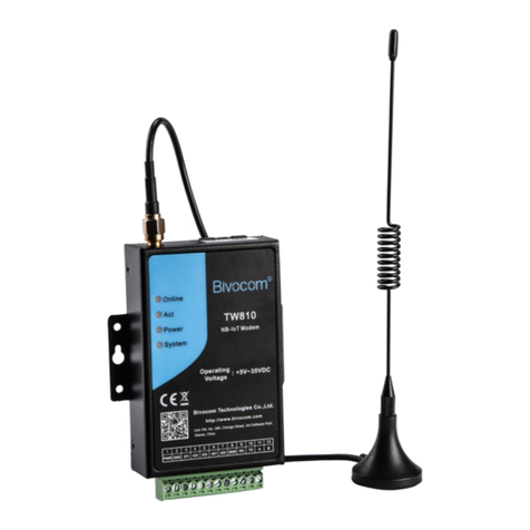
TW810 NB-IoT Modem Host
Cellular antenna(SMA Male)
Power Adapter(12VDC/0.5A)
3- Pin RS232 cable
12-Pin Terminal Block

Addr.: Unit 704, No. A3 Building, Tel: +86-592-6211770
3rd Software Park, Xiamen, China 361000 Fax: +86-592-6211727
www.bivocom.com [email protected]
8
3.2 Dimensions
There are 3 holes for installation at each side of TW810 (Unit: mm)
3.3 Installation

Addr.: Unit 704, No. A3 Building, Tel: +86-592-6211770
3rd Software Park, Xiamen, China 361000 Fax: +86-592-6211727
www.bivocom.com [email protected]
9
3.3.1 SIM/UIM Card
Insert the SIM/UIM card.
TW810 supports normal SIM/UIM only, so if you’re using a Micro SIM or Nano SIM card,
you may need to use a Micro SIM or Nano SIM to Normal SIM card adapter.
Make sure your NB-IoTModem is powered off, then use a needle object(such as a pen) to
push the button near the SIM/UIM card holder, it will flick out immediately. Put the
SIM/UIM card to card holder with chipset upside, insert it to NB-IoT Modem and make
sure it’s tightly matched.
Warning: Never install SIM/UIM card when NB-IoT Modem is powered on.
3.2.2 Cellular Antenna
Fasten the cellular antenna.
Screw the SMA male cellular antenna to TW810 (SMA female interface), make sure it is
screwed tightly to ensure the strength of signal.
3.2.3 Terminal Block, Power Cable and Console Cable
Insert the terminal block to modem correctly.
1) Definition of Terminal Block Interface
PIN No.
Signal
Name
Default Function
Extended Function
1
PWR
Power input anode
NA
2
GND
Power Ground
NA
3
IO1
GPIO, able to check dry contact
signal and 3.3 V switch signal,
output 3.3V switch signal
Reserved RS232 RTS
and
TTL RX
4
IO2
GPIO, able to check dry contact
signal and 3.3 V switch signal,
output 3.3V switch signal
Reserved RS232 CTS
and
TTL TX
5
IO3
GPIO, able to check dry contact
signal and 3.3 V switch signal,
output 3.3V switch signal
Reserved RS232 DCD

Addr.: Unit 704, No. A3 Building, Tel: +86-592-6211770
3rd Software Park, Xiamen, China 361000 Fax: +86-592-6211727
www.bivocom.com [email protected]
10
6
IO4
GPIO, able to check dry contact
signal and 3.3 V switch signal,
output 3.3V switch signal
Customized pulse
output, pulse counter,
analog quantity input,
Reserved RS232 RI
7
IO5
GPIO, able to check dry contact
signal and 3.3 V switch signal,
output 3.3V switch signal
Customized pulse
output, pulse counter,
analog quantity input
8
GND
Power Ground
NA
9
RX
RS232 Receive Data
NA
10
TX
RS232 Transfer Data
NA
11
A
RS485 anode
Reserved RS232 DTR
12
B
RS485 cathode
Reserved RS232 DSR
2) Connect Power Cable and Console Cable
Connect the power supply cable and console cable to terminal block.
The interface of TW810 is industrial terminal block, we suggest you use 28-16AWG power
cable and console cable.
Definition of power cable and console cable in this package are as below
Power Cable (Output 12VDC/0.5A)
Color of cable
Power Output Polarity
Black & White Alternate
Anode
Black
Cathode
RS232 Cable (with DB9 female interface)
Color of Cable
Corresponding DB9-M
Pin Number
Blue
3
Brown
2
Black
5
WARNING: make sure you connect the terminal block to TW810 NB-IoT modem
correctly before power on, or it may cause the damage of device.
3.3 Power Supply
After all the accessories and cables mentioned above are installed very well and correctly,
then plug the power supply to power outlet.
TW810 adopts advanced power technology to improve the stability and adapt to complex
external environment. You can use Bivocom standard power adapter(12VDC/500mA), or
use DC power ranging at 5-35VDC, please make sure the power supply is stable
enough(Ripple shall be less than 300mA, and Instantaneous voltage shall not larger than

Addr.: Unit 704, No. A3 Building, Tel: +86-592-6211770
3rd Software Park, Xiamen, China 361000 Fax: +86-592-6211727
www.bivocom.com [email protected]
11
35V), meanwhile, power shall over 4W.
Note: We suggest you use Bivocom standard power adapter (500mA/12VDC).
3.4 LED Indicators
TW810 has 4 LED indicators, ‘Online’, ‘ACT’, ’Power’, ‘System’, as follows.
4. Serial Port Configuration
Connect TW810 to your laptop or computer through RS232, then open Bivocom
configuration tool (TW810.exe), Click on the left side, choose the right serial
port as below,
LED Indicators
Status
Content
Online
Off
TW810 isn’t connected to server
On
TW810 is connected to server
ACT
Off
No data transfer
Blink
Sending or receiving data
Power
Off
Power Off
On
Power On
System
Off
System works
Blink
System doesn’t works

Addr.: Unit 704, No. A3 Building, Tel: +86-592-6211770
3rd Software Park, Xiamen, China 361000 Fax: +86-592-6211727
www.bivocom.com [email protected]
12
Click , and repower TW810, waiting for entering into configuration status.
4.1 Operations
4.1.1 Save
Click to save the parameters you’ve configured.
4.1.2 Load
Load the parameters of TW810 to config tool and display.
4.1.3 Clear Output
Clear log of config tool.
4.1.4 Version Info
Check the version info of TW810.
4.1.5 Signal Value
Check the signal strength of TW810.
4.1.6 Factory Setting
TW810 returns to factory setting.

Addr.: Unit 704, No. A3 Building, Tel: +86-592-6211770
3rd Software Park, Xiamen, China 361000 Fax: +86-592-6211727
www.bivocom.com [email protected]
13
4.1.7 Restart
Restart TW810
4.1.8 Save Config
Save configuration of TW810 in file format, which you can use it recover the config.
4.1.9 Configure via Saved Config File
Click , and choose the
saved config file, then click to configure TW810.
4.2 Basic Setting

Addr.: Unit 704, No. A3 Building, Tel: +86-592-6211770
3rd Software Park, Xiamen, China 361000 Fax: +86-592-6211727
www.bivocom.com [email protected]
14
4.2.1 Device ID
To identify the TW810 and for device management, if you have many TW810 connected
to server, please make sure all the ID are different.
4.2.2 SIM Card No.
The Number of SIM inserted in this modem.
4.2.3 Work Mode
Keep the default settings-DTU, as work mode MODEM and IMODEM are not supported
on TW810.
DTU (Transfer the data to server through NB-IoT Modem)
Note: the MODEM and IMODEM work mode are only available on TD210 series IP
Modem.
4.2.4 Debug Level
There are 3 levels to choose from the drop-down menu, as below
2:All logs output through RS232/RS485
1: Part of important logs output through RS232/RS485
0: No logs output

Addr.: Unit 704, No. A3 Building, Tel: +86-592-6211770
3rd Software Park, Xiamen, China 361000 Fax: +86-592-6211727
www.bivocom.com [email protected]
15
4.2.5 Communication Baud Rate
Supported baud rate: 300, 600, 1200, 2400, 4800, 9600, 14400, 19200, 38400, 56000,
57600 and 115200.
4.2.6 Databit, Parity and Stopbit
You can choose below from drop-down menu.
8N1 (8 Databit, No Parity, 1 Stopbit)
8E1 (8 Databit, Even Parity, 1 Stopbit)
8O1 (8 Databit, Odd Parity, 1 Stopbit)
7O1 (7 Databit, Odd Parity, 1 Stopbit)
7E1 (8 Databit, Even Parity, 1 Stopbit)
7N1 (7 Databit, No Parity, 1 Stopbit)
4.2.7 Frame Interval (Unit: Millisecond)
When NB-IoT Modem receives packet slicing, increase the value, while for packet
merging, lower the value, 20ms for 115200 baud rate, 50ms for 9600 baud rate and
200ms for 1200 baud rate.

Addr.: Unit 704, No. A3 Building, Tel: +86-592-6211770
3rd Software Park, Xiamen, China 361000 Fax: +86-592-6211727
www.bivocom.com [email protected]
16
4.2.8 Trigger Settings
1) Trigger Type
There are 2 trigger types for TW810 only, AUTO and DATA.
AUTO: Always online
DATA:Sending specific data to trigger TW810 online or offline.
Note: SMSD, CTRL, MIXED are not applicable to TW810, only available on TD210
Cellular modem.
http://www.bivocom.com/index.php?m=content&c=index&a=show&catid=12&id=22
2) Data Trigger On Password
You can set up trigger data in the blank, once the trigger mode is DATA and MIXD, and
TW810 receives the trigger data through RS232/RS485 serial port, it will get online.
3) Data Trigger Off Password
You can set up trigger data in the blank, once the trigger mode is DATA, and TW810
receives the trigger data through RS232/RS485 port, it will get offline.
4) RTC Setting
You can set up the system time for your TW810.

Addr.: Unit 704, No. A3 Building, Tel: +86-592-6211770
3rd Software Park, Xiamen, China 361000 Fax: +86-592-6211727
www.bivocom.com [email protected]
17
4.3 Networking Setting
4.3.1 Network Work Mode
There is one network work mode supported on TW810 right now-NUDP(Pure UDP).
CUDP(Custom UDP) and HUDP(DCUDP) are unavailable now.
TW810 will act as a UDP client when choose NUDP.
Note: To save the power consumption, NB-IoT Modem TW810 only supports UDP.

Addr.: Unit 704, No. A3 Building, Tel: +86-592-6211770
3rd Software Park, Xiamen, China 361000 Fax: +86-592-6211727
www.bivocom.com [email protected]
18
4.3.2 Data Center Number
1) You can configure up to 5 data centers.
0 means TW810 will not connect to NB-IoT network.
1 means TW810 only supports 1 data center, TW810 will connect to main center,
once it couldn’t connect to backup center, it will continue to connect to main center till
it’s connected.
2-5 means TW810 supports multi centers, and all the other centers will get sync data.
Note: if there is not backup center, please set up the same address and port for main
center and backup center
2) Center Addr.+Port
It can be configured as DNS or IP address.
3) Center DNS Server
When you use DNS for center, a DNS server is required to analytic the corresponding IP
address.

Addr.: Unit 704, No. A3 Building, Tel: +86-592-6211770
3rd Software Park, Xiamen, China 361000 Fax: +86-592-6211727
www.bivocom.com [email protected]
19
4.3.3 Dialing Settings
APN: cellular network access code
Username: authentication username of NB-IoT network
Password: authentication password of NB-IoT network
Call center: dial number of call center for NB-IoT network
Note: Different carriers may have different APN, Username, Password and Call
Center, please ask your mobile carriers for those info if you have any questions.
4.3.4 Heartbeat Interval
Heartbeat time, we suggest you keep it as default settings.
4.3.5 Auto Back to Main Server
Y
Auto back to main server.
N
Don’t auto back to main server.
This setting will only work when both main and backup center are enabled, under this
work mode, if main center fails, TW810 will auto connect to backup center. If you choose
‘Y’, TW810 will check whether main center is recovery or not, if yes, it will switch to main
center, and disconnect with backup center. While if choose ‘N’, TW810 will not check
whether main center is recovery or not.

Addr.: Unit 704, No. A3 Building, Tel: +86-592-6211770
3rd Software Park, Xiamen, China 361000 Fax: +86-592-6211727
www.bivocom.com [email protected]
20
4.3.6 Custom Register String
You can configure it when network work mode is configure as CUDP, but you can also
choose not to configure it, which means register string won’t be sent.
Note: the length of register string is up to 70 bytes.
4.3.7 Custom Heartbeat String
You can configure it when network word mode is configure as CUDP, but you can also
choose not to configure it, which means register string won’t be sent.
Note: the length of register string is up to 70 bytes.
4.3.8 Transfer Meaning
Y means Yes
N means No
We suggest you keep it as default settings-Y
4.3.9 TCP MTU
We suggest you keep it as default settings, as it is not supported by TW810.
4.3.10 Multi Center Reconnect Interval
Only available when data center number is 2-5.
This manual suits for next models
2
Table of contents
Other Bivocom Modem manuals
