Koyoe KY-EST06KH User manual

1
User Manual
3-Phase Hybrid Inverter
KY-EST06KH~KY-EST20KH
V1.0

2
All Rights Reserved
No part of this document can be reproduced in any form or by any means without the prior written
permission of Jiangsu KOYOE Energy Technology Co., Ltd(hereinafter “KOYOE”).
Trademarks Rights
The logo and other KOYOE trademarks used in this manual are owned by Jiangsu
KOYOE Energy Technology Co., Ltd.
All other trademarks or registered trademarks mentioned in this document are owned by their
respective owners.
Software Copyrights
It is prohibited to use data contained in firmware or software developed by KOYOE, in
part or in full, for commercial purposes by any means.
It is prohibited to perform reverse engineering, cracking, or any other operations that
compromise the original program design of the software developed by Jiangsu KOYOE
Energy Technology Co., Ltd.

3
About This Manual
The manual mainly introduces product information, installation guide, operation and
maintenance. This manual cannot contain complete information about photovoltaic systems. You
can find more information about other devices at www.koyoe.com or on the relevant component
manufacturer's web pages.
Scope of application
This manual is valid for the following inverter models:
- KY-EST06KH
- KY-EST08KH
- KY-EST10KH
- KY-EST12KH
- KY-EST15KH
- KY-EST17KH
- KY-EST20KH
They will be referred to as “inverter” hereinafter unless otherwise specified.
How to Use the Manual
Before using or operating the inverter, please read this manual and other relevant documents
carefully.
The contents in this manual are owned by Jiangsu KOYOE Energy Technology Co., Ltd., and
shall not be reproduced or published in any form without the prior written permission of our
company.
The contents of the manual may be periodically updated or revised as a result of product
development. Information in this manual is subject to change without prior notice. The latest
handbook is available at www.koyoe.com.

4
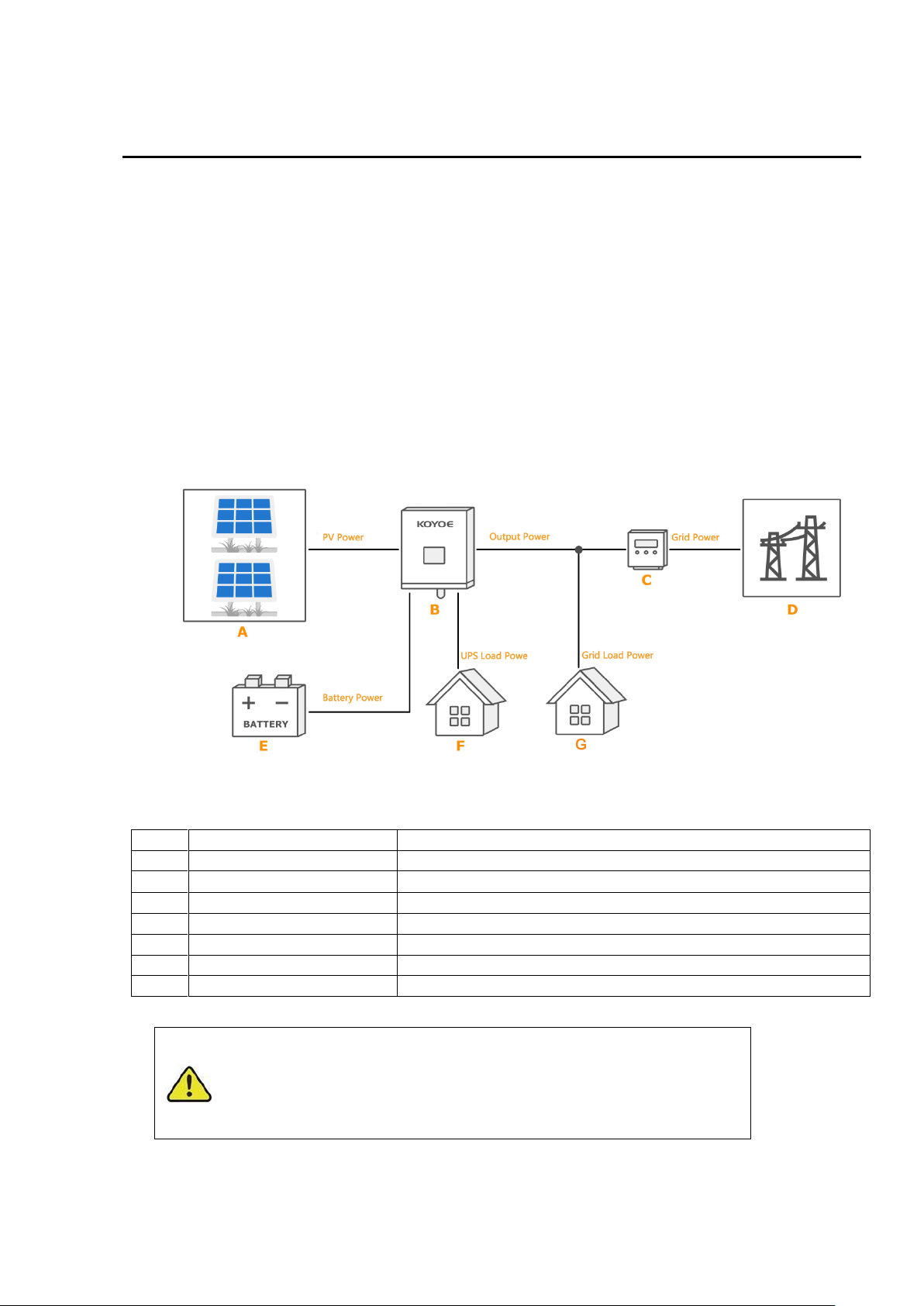
1. System Introduction............................................................................................................................ 7
1.1. Product Introduction ...........................................................................................................8
1.1.1 Inverter Introduction ..........................................................................................................8
1.1.2 Energy Mete......................................................................................................................8
1.1.2.1 Operating manual of Meter.............................................................................................8
2. Safety Instructions .............................................................................................................................18
2.1. PV Panels .........................................................................................................................18
2.2. Utility Grid..........................................................................................................................18
2.3. Battery...............................................................................................................................19
2.4. Inverter..............................................................................................................................19
2.5. Skills of Qualified Personnel..............................................................................................22
3. Energy Management ..............................................22
3.1. Self Use.............................................................................................................................22
3.2. Forced Charging................................................................................................................24
3.3. Forced Discharge..............................................................................................................24
3.4. Peak Shaving....................................................................................................................25
3.5. Maintenance......................................................................................................................25
3.6. Emergency Charging.........................................................................................................26
3.7. Off Grid .............................................................................................................................26
4. Working Stetes...................................................................................................................................27
4.1 Waiting...............................................................................................................................27
4.2 Checking............................................................................................................................27
4.3 Normal ...............................................................................................................................27
4.4 Fault...................................................................................................................................27
4.5 Upgrade.............................................................................................................................29
5. Function Description..........................................................................................................................29
5.1 Safety Function ..................................................................................................................29
5.2 Power quality response modes...........................................................................................35
5.3 Energy Conversion and Management ................................................................................35
5.4 Power Derating...................................................................................................................35
5.5 External Demand Response(DRMs)..............................................................................36
6. Unpacking and Storing......................................................................................................................37
6.1. Unpacking and Inspecting.................................................................................................37
6.2. Packing List.......................................................................................................................38
6.3. Inverter Storage.................................................................................................................39
7. Mechanical Mounting.........................................................................................................................40

5
7.1. Safety during Mounting......................................................................................................40
7.2. Mounting Location.............................................................................................................40
8. ELECTRICAL WIRING CONNECTION...........................................................................................43
8.1. Safety Instruction...............................................................................................................43
8.2. Terminal Description..........................................................................................................44
8.3. Electrical Connection Overview.........................................................................................46
8.4. Additional Grounding Connection......................................................................................49
8.5. PV CONNECTION ............................................................................................................52
8.6. Battery CONNECTION......................................................................................................56
8.7. AC Cable Connection........................................................................................................60
8.8. EPS Cable Connection......................................................................................................62
8.9. Communication Connection...............................................................................................62
8.10. Meter Connection............................................................................................................62
8.11. Generation Limit and Export Limit Control.......................................................................62
8.11.1 Soft export Limit Control ............................................................................................62
8.11.2 Hard export Limit Control...........................................................................................62
8.11.3 Soft generation limit control........................................................................................62
8.11.4 Hard generation limit control......................................................................................62
9. Commissioning...................................................................................................................................64
9.1. Inspection before Commissioning......................................................................................69
9.2. Powering on the System....................................................................................................71
9.3. LCD Introduction ...............................................................................................................72
10. Decommissioning.............................................................................................................................74
10.1. Decommissioning the Inverter.........................................................................................74
10.1.1 Disconnecting the Inverter............................................................................................74
10.1. 2 Dismantling the Inverter................................................................................................74
10.1.3 Disposing the Inverter...................................................................................................74
11. Communication and Monitoring......................................................................................................75
11.1. Summery.........................................................................................................................75
11.2. Communication ...............................................................................................................75
11.3. RS-485 Communication .................................................................................................76
11.4. WiFi / GPRS Communication .........................................................................................76
11.5. Monitoring ......................................................................................................................76
12. Maintenance and Repair.................................................................................................................79
12.1. Precautions during Maintenance .....................................................................................79
12.2 .Safety Requirements during Maintenance.......................................................................79

6
12.3. Daily Maintenance...........................................................................................................80
13. Technical data..................................................................................................................................80
13.1 .Technical Parameters And Certificates............................................................................80
14. Warranty commitment .....................................................................................................................83
15. Contact Information .........................................................................................................................84
Appendix I: Common Problems............................................................................................................85
Appendix II: Abbreviations of Terms.....................................................................................................86

7
1. System Introduction
KY-EST06KH/ KY-EST08KH/ KY-EST10KH/KY-EST12KH/ KY-EST15KH/ KY-EST17KH/ KY-
EST20KH series inverter, also known as hybrid or bidirectional solar inverter, is suitable for
energy management of photovoltaic, battery, load, power grid and other solar energy systems.
Electricity from the photovoltaic panels is used for residential electricity, and excess power can be
stored in batteries. When the battery is fully charged, users can send excess power to the utility
grid.
When the photovoltaic power is not enough to meet the user's load demand, the battery will
discharge to the load. If there is not enough energy stored in the battery, the grid will supply
power to the load through the system.
The inverter with no transformer topology, and there is no isolation between DC input and AC
output. The adaptive PV model must meet IEC61730 Class A. The energy management system is
shown in Figure 1-1.
Fig.1-1 PV Energy Storage System
Item
Description
Remark
A
PV strings
Photovoltaic panel
B
Inverter
Model:KY-EST20KH
C
Energy meter(three-phase)
RS 485 communication with inverter
D
Utility grid
Grid grouding system types: TT,TN
E
Battery System
A Li-ion battery or a lead-acid battery.
F
UPS load
User load connected to the inverter EPS port.
G
Grid load
User loads connected to the grid.
Warning!
-For the TT utility grid, the N line voltage to ground must be 30V
or less.
- The maximum power of home load and EPS load
must be less than the rated power of inverter.

8
1.1. Product Introduction
1.1.1 Inverter Introduction
Model Description
The inverter model description is as follows (Take KY-EST20KH as an example):
KY -EST 20K H
High voltage battery(180V~700V)
The inverter power is 20KW
The inverter is three phase hybrid inverter
Code of KOYOE
Model
Nominal Output Power
Nominal Grid Voltage
KY-EST06KH
6000W
3/N/PE,230/400V
KY-EST08KH
8000W
KY-EST10KH
10000W
KY-EST12KH
12000W
KY-EST15KH
15000W
KY-EST17KH
17000W
KY-EST20KH
20000W
Appearance
The following figure shows the inverter appearance, which is for reference only. The actual
product that you receive may differ.

9
Fig1-2.Appearance(KY-EST06-10KH)
Fig1-3.Appearance(KY-EST12-20KH)
Be careful!
This inverter contains a PV switch. For safety reasons, it is
recommended to have a DC switch between the PV array and the
inverter PV input terminals (mandatory in some countries).
Dimensions
The following figure shows the dimensions of the inverter. See Figure 1-4 and the following
table for the description of LCD panel.

10
Dimensions KY-EST06-10KH(unit: mm)
Dimensions KY-EST12-20KH(unit: mm)

11
Fig1-4.LCD panel
No.
Name
Description
1
Run LED(Green)
After the inverter is powered on, the LED flashes. When the inverter
is in normal mode, the LED will always be bright
2
COM LED(Yellow)
When the inverter communicates through WIFI,GPRS and upper
computer, the LED flashes
3
ALARM LED(Red)
When an alarm occurs, the LED flashes. When the inverter fails, the
LED will always be on
4
LCD Screen
To display the information
5
ESC Key
Exit the current menu
6
Up Key
Page up or move cursor
7
Down Key
Page down or move cursor
8
Enter Key
Enter the current menu
1.1.2 Energy Meter
The Energy Meter is installed next to the grid main switch to detect the electrical measured
values at the grid-connected point. It communicates with the inverter via an RS485
connection. The dimensions are shown below. Please refer to the wiring guide for electricity
meters.The meter mode is:SDM630MCT(40mA) ,The meter manufacture is EASTRON.

12
Fig1-5.Three-phase Meter Dimension (unit: mm)

13
The following is the electrical connection diagram of the electricity meter. For detailed operation of
the electricity meter, please refer to the operation manual of the electricity meter in the
accessories. If you have any questions, please contact our customer service.

14
1.1.2.1 Operating manual of Meter
If the wiring is OK, the instrument will display the following results on the screen after automatic power
on self-test.
The functions of the keys on the right side of the instrument are shown in the figure below.
Each successive press of the button selects a new parameter:

15
Each successive press of the button selects a new parameter:

16
Each successive press of the button selects a new parameter:

17
Each successive press of the button selects a new parameter:

18
2. Safety Instructions
The inverter is strictly complying with the relevant safety regulations of product design and testing.
In order to use this product more safely and reliably, the following lists the information related to
different categories of safety. In the process of installation, operation and maintenance, please
carefully read and observe the instructions and precautions of the inverter, otherwise it will cause
loss of personal and property.
NOTICE!
-The safety instructions in this manual cannot cover all the
precautions that should be followed. Perform operations
considering actual on site conditions.
-KOYOE shall not be held liable for any damage caused by
violation of the safety instructions in this manual.
2.1. PV Panels
Users must ask professionals to install the photovoltaic panels according to the user manual.
Please pay attention to the following matters during installation:
- Photovoltaic panels generate electricity when they are exposed to sunlight and can cause fatal
voltages and shocks.
- The inverter is a multi-power system. Operators must wear appropriate personal protective
equipment: safety helmet, insulation wire, gloves, etc.
- The operator must use measuring equipment to ensure that the output cable of the PV panel is
free of voltage before contacting it.
- All the warnings on the PV panel and in its manual must be followed.
2.2. Utility Grid
Warning!
-The inverter must only be operated with PV strings of
protection class II in accordance with IEC 61730, application
class A.
-It is not permitted for the positive pole or the negative pole of
the PV strings to be grounded.
- Damages to the product due to a faulty or damaged PV
installation are not covered by warranty.

19
Please comply with the relevant regulations of power grid.
2.3. Battery
Please use the battery recommended by our company and pay attention to the following:
2.4. Inverter
Be careful!
- All electrical connections must comply with local and national
standards.
-Only with the permission of the utility grid, the inverter can be
connected to the utility grid.
DANGER!
- A short circuit or incorrect installation of a battery can release
energy and may result in a combustion or fire hazard.
- There may be fatal voltage in the battery terminals and cables
of the inverter. Contact with the cables and terminals in the
inverter may cause serious personal injury or even death.
Warning!
Provide sufficient ventilation for the battery system to prevent
flames and sparks from the explosive hydrogen gas that the
batteries release.
Due to the dangers of hydrogen gas and battery electrolyte:
-locate batteries in a designated area, complying with the local
regulations.
-protect the enclosure against destruction.
-do not open or deform the battery.
-whenever working on the battery, wear suitable personal
protective equipment (PPE) such as rubber gloves, rubber
boots and goggles.
-rinse acid splashes thoroughly with clear water for a long time
and consider consulting a doctor.
Warning!
-Improper settings or maintenance can permanently damage
the battery.
-Incorrect inverter parameters will lead to the premature aging
of battery.

20
Warning Label
DANGER!
Improper handling can be a danger of electric shock.
Do not open the shell at any time. Opening the shell without
authorization will not continue to enjoy the warranty.
Warning!
Inverter operation is prohibited improper operation.
- Do not pull out PV connectors, AC connectors and battery
connectors when the inverter is running.
- When turning off the inverter, all power supplies of the inverter,
including PV, grid and batteries, must be turned off and wait 10
minutes before operating the inverter.
- Before pulling out any connectors, you must ensure that the
connectors have no voltage or current.
Warning!
After completion of installation, all safety instructions, warning
labels and nameplates on the inverter must meet the following
conditions:
-Must be clearly legible.
-Should not be removed or covered.
Warning!
Risk of burns due to hot components .
-Do not touch any hot parts (such as heat sinks) during operation.
-Only the LCD panel and the DC switch can safely be touched at
any time.
Warning!
- Only professionals can change the type Settings of safety
regulations.
- Unauthorized changes to safety regulations lead to damage of
the inverter will not enjoy warranty service.
- Please be aware of the risk of static electricity from damaging the
inverter.
- Do not disassemble the inverter and contact the internal devices.
- Connectors that contact the inverter directly while the inverter is
running are prohibited.
This manual suits for next models
1
Table of contents
Popular Inverter manuals by other brands

Hitachi
Hitachi WJ200 Series Software Quick reference guide

Shenzhen Huangjintai Electronic
Shenzhen Huangjintai Electronic NK-GP1000 user manual

SEW-Eurodrive
SEW-Eurodrive MOVITRAC B operating instructions

Ozone Solutions
Ozone Solutions HVAC-560 Operation, Installation and Maintenance Instructions

Tundra
Tundra M1500 Quick troubleshooting guide

Magnum Energy
Magnum Energy ME2000-20B Supplement to onwer's manual