QC STATION 2
1. Tip keyboard back and forth to ensure no loose screws inside
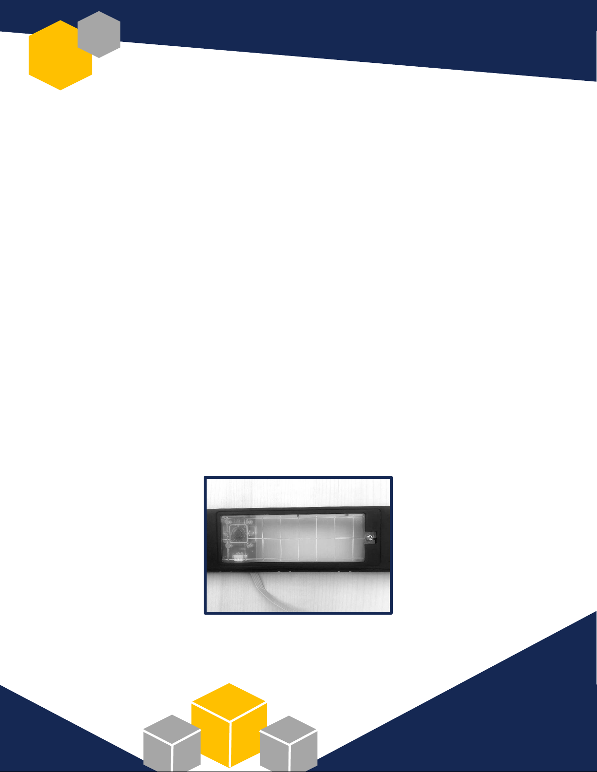
2. Press and wiggle TCS1 to ensure secure installation
3. Inspect TCS1 to ensure no portion of gasket is showing
4. Test operation of each key using PassMark Keyboard Test
5. Check for loose keys caps
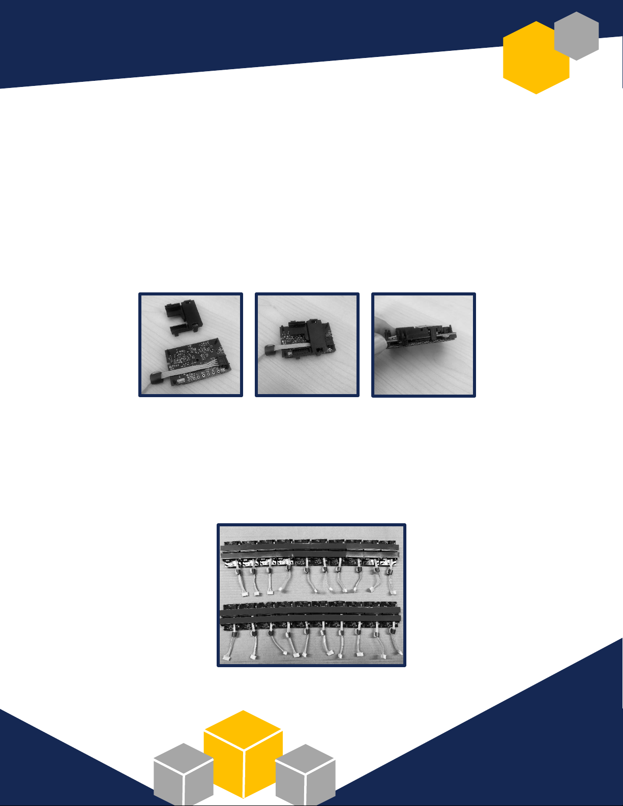
6. Check for correct RFID configuration using RFIDeas pcProx config test
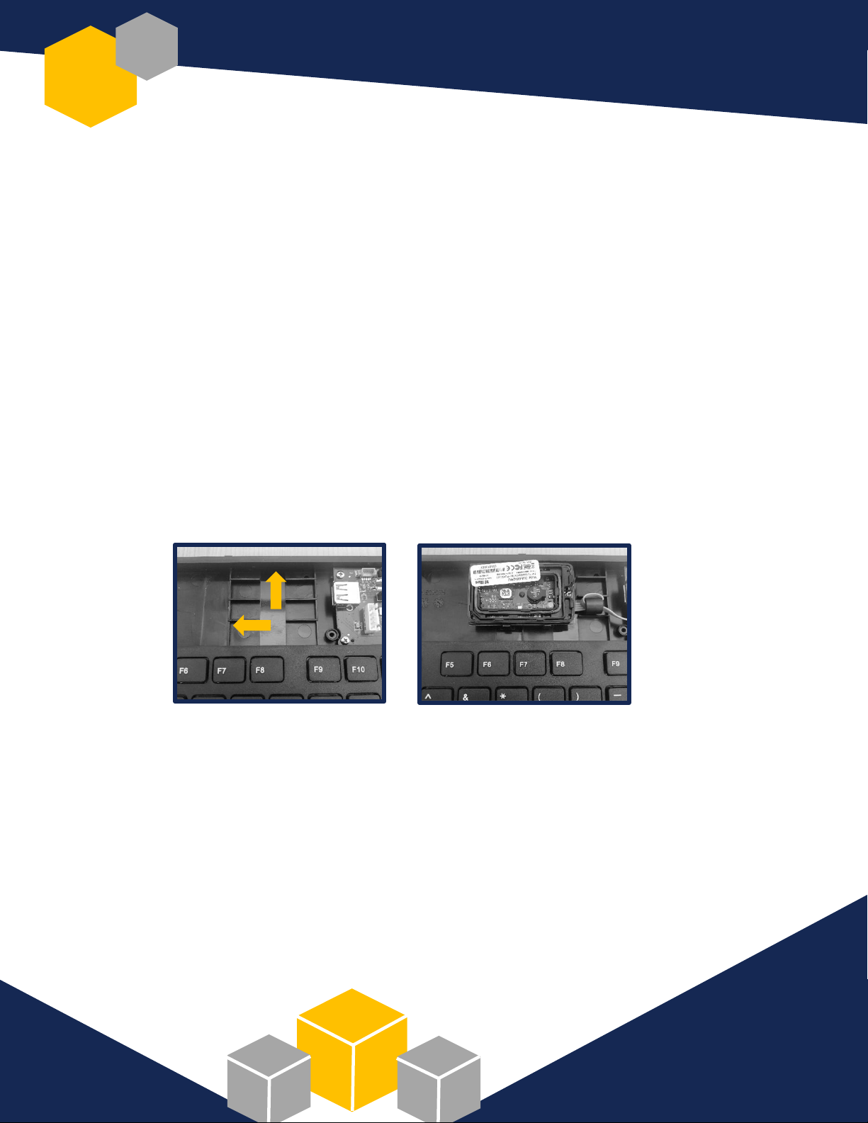
7. Use Windows Device Manager to confirm presence of Bluegiga Low Energy module
8. Test programming of tact switch: press tact switch button; three keyboard LEDs should flash green
9. Run secure login/logoff test as follows:
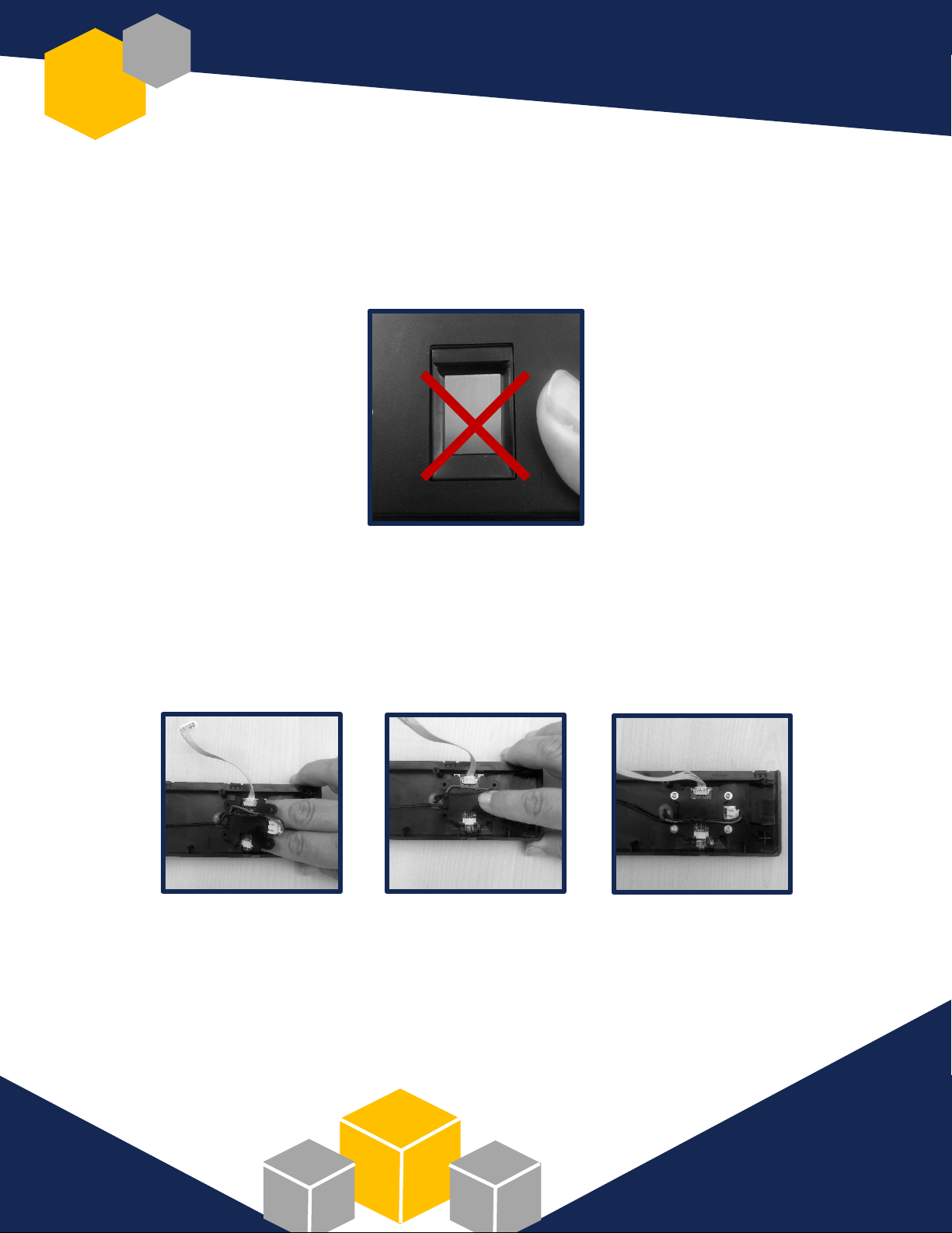
Log in to Imprivata OneSign using fingerprint placement on TCS1; ensure TCS1 LED flashes blue
Log out of Imprivata OneSign using 125 kHz card; ensure strong beep and green LED flash
Repeat login procedure using fingerprint
Log out of Imprivata OneSign using 13.56 Mhz card; ensure strong beep and green LED flash
10. Ensure window and bubble labels are correct and applied straight; remove extra glue from label
11. Verify top housing and keyboard base are joined correctly
12. Apply long LED strip label where the top assembly meets the keyboard base; ensure label is
straight and properly aligned with LED lights
13. Center KSI logo label between “Enter” & “4” keys horizontally, “End” & “Page Up” arrow vertically
14. Confirm keyboard footbar is operational
15. Verify four keyboard feet are in place
16. Ensure five screws are in place on underside of keyboard
17. Apply QC sticker in upper righthand corner of product label on back of keyboard
18. Perform final, overall visual check of keyboard; clean with cloth, if necessary
19. Place keyboard in pink plastic shipping bag, neatly folding excess plastic around keyboard
20. Place in sequential serial number order in shipping box slots
21. Ensure product barcode label is present on serial number sheet and shipping box
22. Verify serial numbers on keyboards match factory-issued serial number sheet
23. Place serial number sheet in vacant shipping box slot