KTR OAC Series Manual

Oil/air cooler
Series OAC
Operating/Assembly instructions
KTR-N
Sheet:
Edition:
43210 EN
1 of 23
6
Please observe protection
note ISO 16016.
Drawn:
2019-10-23 Pz/Str
Replacing:
KTR-N dated 2017-06-22
Verified:
2019-11-04 Pz
Replaced by:
Oil/air cooler
series
OAC
according to directive 2014/34/EU
Oil/air cooler; example: OAC100
Oil/air cooler; example: OAC200 to OAC2000

Oil/air cooler
Series OAC
Operating/Assembly instructions
KTR-N
Sheet:
Edition:
43210 EN
2 of 23
6
Please observe protection
note ISO 16016.
Drawn:
2019-10-23 Pz/Str
Replacing:
KTR-N dated 2017-06-22
Verified:
2019-11-04 Pz
Replaced by:
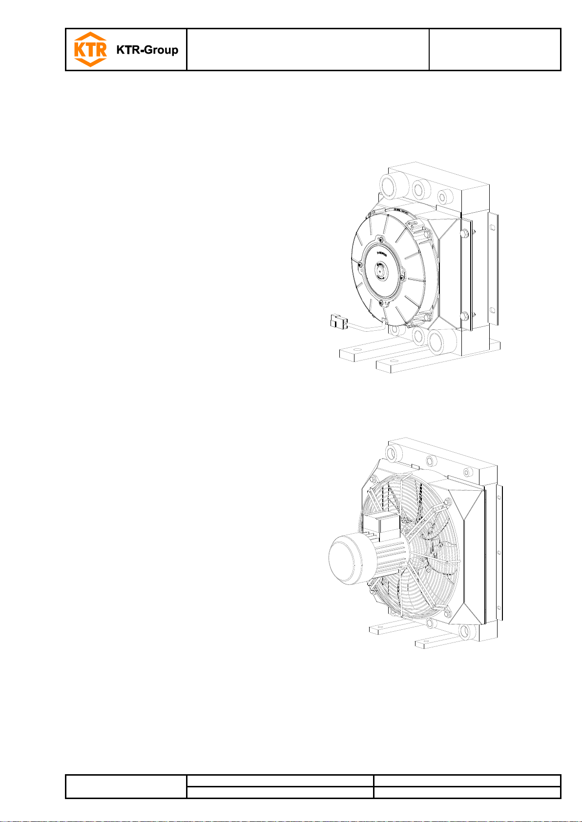
The oil/air cooler series OAC is an efficient high-performance cooler. It has a compact design and was
developed for cooling hydraulic oil, gear oil, lubricant and water-glycol.
1Technical data 3
2Advice 7
2.1 General advice 7
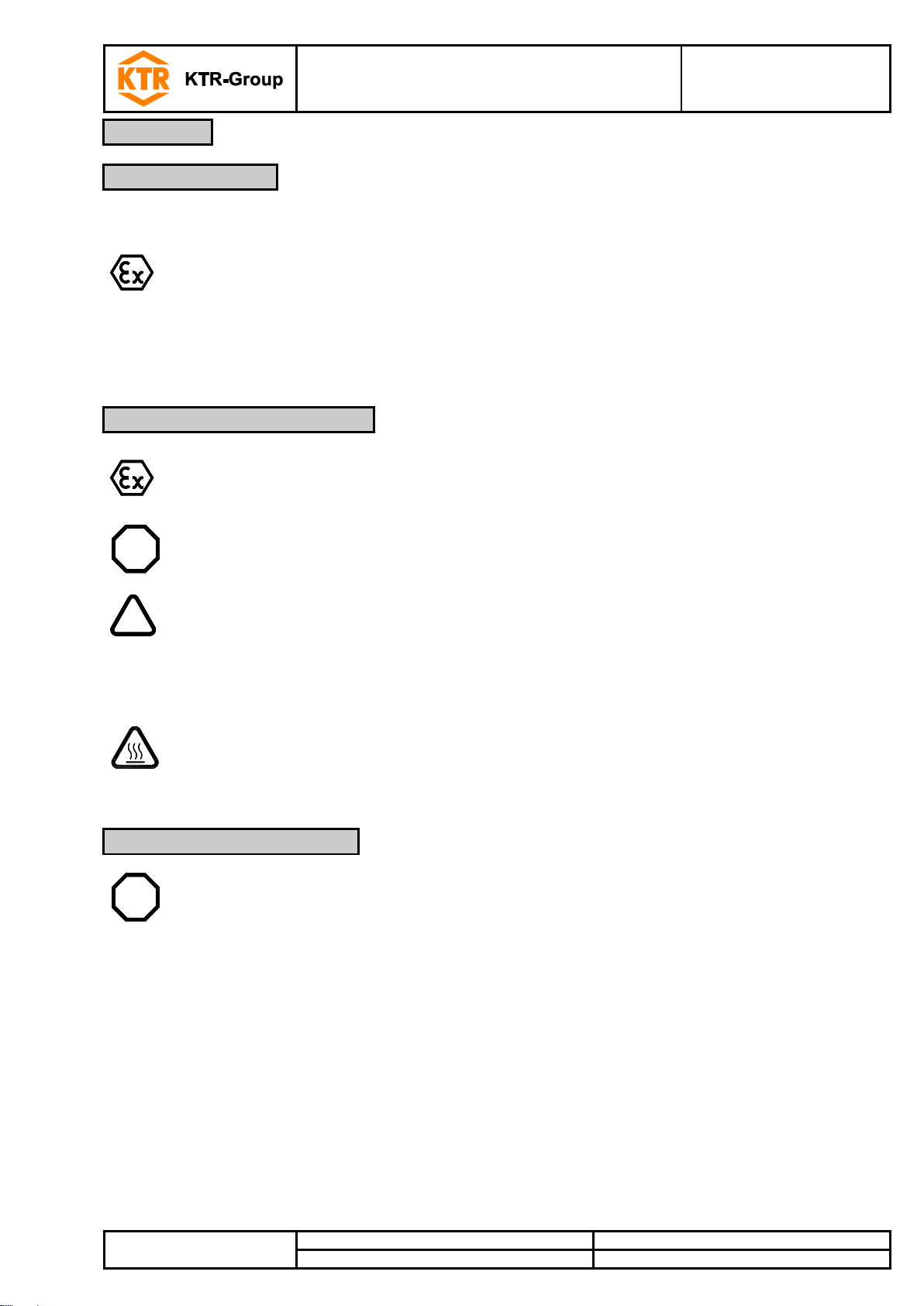
2.2 Safety and advice symbols 7
2.3 General hazard warnings 7
2.4 Intended use 8
3Storage, transport and packaging 8
3.1 Storage 8
3.2 Transport and packaging 8
4Assembly 9
4.1 Components of oil/air cooler 9
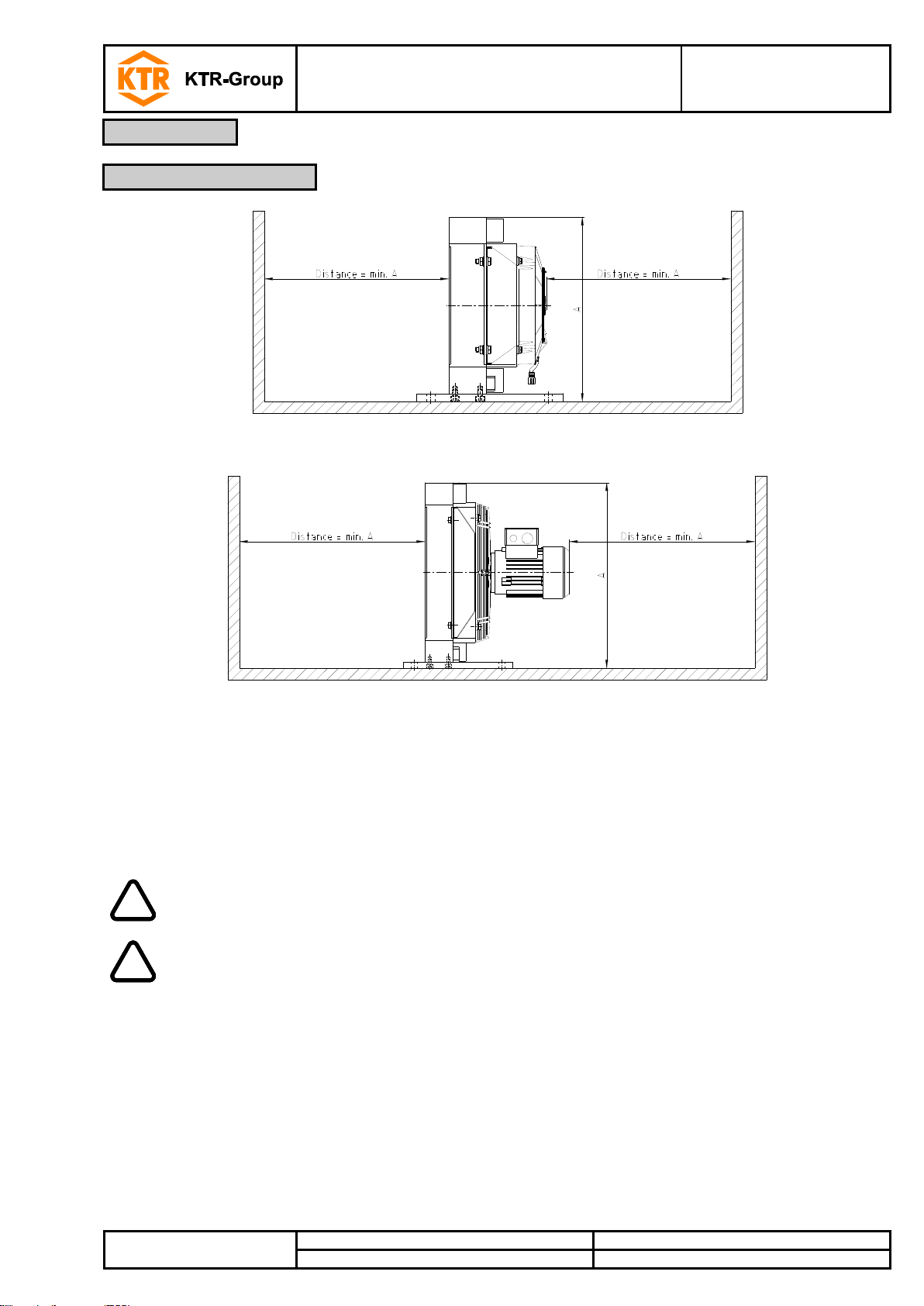
4.2 Place of installation 10
4.3 Assembly of oil/air cooler 11
4.4 Thermal switch 11
4.5 Operating pressure and temperature 11
4.6 Electrical connection 12
4.7 Cooling medium 12
4.8 Cleaning 13
4.9 Marking of standard oil/air cooler 13
4.10 Diagrammes - pressure loss and power 13
4.11 Assembly - disassembly of the oil/air cooler into components 15
5Start-up 16
6Maintenance and service 16
7Spares inventory, customer service addresses 17
8Enclosure A
Advice and instructions regarding the use in potentially explosive atmospheres 18
8.1 Intended use in potentially explosive atmospheres 18
8.2 Marking for potentially explosive atmospheres 19
8.3 Start-up for the use in potentially explosive atmospheres 20
8.4 Permissible accessories for the use in potentially explosive atmospheres 21
8.5 EC Certificate of incorporation 22
8.6 EU Certificate of conformity 23
Table of contents

Oil/air cooler
Series OAC
Operating/Assembly instructions
KTR-N
Sheet:
Edition:
43210 EN
3 of 23
6
Please observe protection
note ISO 16016.
Drawn:
2019-10-23 Pz/Str
Replacing:
KTR-N dated 2017-06-22
Verified:
2019-11-04 Pz
Replaced by:
Illustration 1: OAC100 - OAC400 (12/24V)
Illustration 2: OAC500 (12/24V)
Illustration 3: OAC600 (12/24V)
Table 1: Dimensions - 12/24V
Cooler type
Dimensions [mm]
L
L1
L2
L3
L4
B
B1
B2
H
H1
H2
H3
OAC100-01
167
65
250
200
50
250
225
100
300
150
-
255
OAC100-02
OAC200-01
167
65
250
200
50
350
325
174
410
240
-
360
OAC200-02
OAC300-01
230
65
250
200
49
446
421
200
500
320
-
450
OAC300-02
OAC400-01
260
95
280
230
55.5
446
421
200
500
320
-
450
OAC400-02
OAC500-01
259
95
340
280
40
460
435
130
670
400
200
657
OAC500-02
OAC600-01
222
95
340
280
40
607
582
280
770
500
200
770
OAC600-02
Cooler type
Dimensions [mm]
H4
H5
d
d1
C1
C2
C3
C4
M
F
G
E
OAC100-01
14
-
14
-
-
-
-
-
-
65
-
164
OAC100-02
OAC200-01
14
-
14
-
-
-
-
-
-
115
-
219
OAC200-02
OAC300-01
14
-
14
-
-
-
-
-
-
160
-
264
OAC300-02
OAC400-01
14
-
14
-
-
-
-
-
-
160
-
264
OAC400-02
OAC500-01
70
-
13.5
38
95
69.9
77
35.7
M12
150
157.5
405
OAC500-02
OAC600-01
70
-
13.5
51
105
77.8
90
42.9
M12
225
226
-
OAC600-02
1 Technical data

Oil/air cooler
Series OAC
Operating/Assembly instructions
KTR-N
Sheet:
Edition:
43210 EN
4 of 23
6
Please observe protection
note ISO 16016.
Drawn:
2019-10-23 Pz/Str
Replacing:
KTR-N dated 2017-06-22
Verified:
2019-11-04 Pz
Replaced by:
Illustration 4: OAC200 - OAC400 (230/400V)
Illustration 5: OAC500 - OAC800 (230/400V)
Illustration 6: OAC850 - OAC2000 (230/400V)
Table 2: Dimensions - 230/400V
Cooler type
Dimensions [mm]
L
L1
L2
L3
L4
B
B1
B2
H
H1
H2
H3
OAC200-03
334
65
250
200
50
350
325
174
410
240
-
360
OAC300-03
404
65
250
200
49
446
421
200
500
320
-
450
OAC400-03
434
95
280
230
55.5
446
421
200
500
320
-
450
OAC500-03
431
95
340
280
40
460
435
130
670
400
200
657
OAC600-03
532
95
340
280
40
607
582
280
770
500
200
770
OAC700-03
542
95
340
280
40
608
582
280
920
700
300
920
OAC800-03
665
140
450
390
40
701
676
280
920
700
300
920
OAC850-03
667
95
500
180
-
870
835
350
960
690
230
910
OAC900-03
670
95
590
210
-
995
955
440
1270
1000
600
1182
OAC1000-03
690
113
615
210
-
995
955
440
1270
1000
600
1182
OAC2000-03
900
140
750
210
-
1286
1206
525
1420
1000
600
1332
Cooler type
Dimensions [mm]
H4
H5
d
d1
C1
C2
C3
C4
M
F
G
E
OAC200-03
14
-
14
-
-
-
-
-
-
115
-
219
OAC300-03
14
-
14
-
-
-
-
-
-
160
-
264
OAC400-03
14
-
14
-
-
-
-
-
-
160
-
264
OAC500-03
70
-
13.5
38
95
69.9
77
35.7
M12
150
157.5
405
OAC600-03
70
-
13.5
51
105
77.8
90
42.9
M12
225
226
455
OAC700-03
70
-
13.5
51
105
77.8
90
42.9
M12
225
226
530
OAC800-03
70
-
13.5
51
105
77.8
90
42.9
M12
272
273
530
OAC850-03
42
-
14
51
105
77.8
90
42.9
M12
350
340
523
OAC900-03
42
200
14
73
135
106.5
100
62
M16
372.5
390
678
OAC1000-03
42
200
14
73
135
106.5
100
62
M16
372.5
390
678
OAC2000-03
45
200
14
73
135
106.5
100
62
M16
532
532
756
1 Technical data

Oil/air cooler
Series OAC
Operating/Assembly instructions
KTR-N
Sheet:
Edition:
43210 EN
5 of 23
6
Please observe protection
note ISO 16016.
Drawn:
2019-10-23 Pz/Str
Replacing:
KTR-N dated 2017-06-22
Verified:
2019-11-04 Pz
Replaced by:
Illustration 7: OAC200 - OAC400 (hydraulic)
Illustration 8: OAC500 - OAC800 (hydraulic)
Illustration 9: OAC850 - OAC1000 (hydraulic)
Table 3: Dimensions - hydraulic
Cooler type
Dimensions [mm]
L
L1
L2
L3
L4
B
B1
B2
H
H1
H2
H3
OAC200-04
245
65
250
200
50
350
325
174
410
240
-
360
OAC300-04
295
65
250
200
49
446
421
200
500
320
-
450
OAC400-04
325
95
280
230
55.5
446
421
200
500
320
-
450
OAC500-04
323
95
340
280
40
460
435
130
670
400
200
657
OAC600-04
400
95
340
280
40
607
582
280
770
500
200
770
OAC700-04
411
95
340
280
40
608
582
280
920
700
300
920
OAC800-04
546
140
450
390
40
701
676
280
920
700
300
920
OAC850-04
471
95
500
180
-
870
835
350
960
690
230
910
OAC900-04
475
95
615
210
19.5
995
955
440
1270
1000
600
1182
OAC1000-04
505
113
615
210
-
995
955
440
1270
1000
600
1182
Cooler type
Dimensions [mm]
H4
H5
d
d1
C1
C2
C3
C4
M
F
G
E
OAC200-04
14
-
14
-
-
-
-
-
-
115
-
219
OAC300-04
14
-
14
-
-
-
-
-
-
160
-
264
OAC400-04
14
-
14
-
-
-
-
-
-
160
-
264
OAC500-04
70
-
13.5
38
95
69.9
77
35.7
M12
150
157.5
405
OAC600-04
70
-
13.5
51
105
77.8
90
42.9
M12
225
226
455
OAC700-04
70
-
13.5
51
105
77.8
90
42.9
M12
225
226
530
OAC800-04
70
-
13.5
51
105
77.8
90
42.9
M12
272
273
530
OAC850-04
42
-
14
51
105
77.8
90
42.9
M12
350
340
523
OAC900-04
42
200
14
73
135
106.5
100
62
M16
372.5
390
678
OAC1000-04
42
200
14
73
135
106.5
100
62
M16
372.5
390
678
1 Technical data

Oil/air cooler
Series OAC
Operating/Assembly instructions
KTR-N
Sheet:
Edition:
43210 EN
6 of 23
6
Please observe protection
note ISO 16016.
Drawn:
2019-10-23 Pz/Str
Replacing:
KTR-N dated 2017-06-22
Verified:
2019-11-04 Pz
Replaced by:
Table 4: Fan drive - 12/24V
Cooler type
[V]
Drive
[kW]
Speed
[rpm]
Amperage
[A]
Protection class
Fan Ø
[mm]
Weight
[kg]
OAC100-01
12
0.0864
3950
7.2
IP68
190
6
OAC100-02
24
0.0624
3625
2.6
OAC200-01
12
0.0984
2838
8.2
280
11
OAC200-02
24
0.1056
2925
4.4
OAC300-01
12
0.2208
3080
18.4
350
16
OAC300-02
24
0.2256
2730
9.4
OAC400-01
12
0.2208
3080
18.4
22
OAC400-02
24
0.2256
2730
9.4
OAC500-01
12
0.2424
2600
20.2
385
30
OAC500-02
24
0.2352
2700
9.8
OAC600-01
12
2x 0.0984
2838
2x 8.2
280
43
OAC600-02
24
2x 0.1056
2925
2x 4.4
Table 5: Fan drive - 230/400V with 50Hz or 440V with 60Hz
Cooler type
Drive [kW]
Speed [rpm]
Amperage [A]
Protection class
Fan Ø
[mm]
Noise
[dbA]
Weight
[kg]
50Hz
60Hz
50Hz
60Hz
50Hz
60Hz
Standard
Marine
OAC200-03
0.18
0.21
1350
1650
0.58
0.57
IP55
IP56
280
66
16
OAC300-03
0.37
0.43
1370
1670
1.04
1.02
380
76
24
OAC400-03
29
OAC500-03
78
37
OAC600-03
0.75
0.86
1440
1740
1.79
1.72
520
57
OAC700-03
70
OAC800-03
1.5
1.75
1435
1730
3.3
3.3
630
97
OAC850-03
2.2
2.55
965
1165
5.2
4.75
750
79
130
OAC900-03
-
-
-
900
85
186
OAC1000-03-6
87
198
OAC1000-03-4
7.5
1470
97
223
OAC2000-03-6
975
9.33
-
-
1000
92
357
OAC2000-03-4
18.5
1470
100
429
Table 6: Fan drive - hydraulic
Cooler type
Swallowing capacity
[ccm]
Speed
[rpm]
Fan Ø
[mm]
Noise
[dbA]
Weight
[kg]
OAC200-04-06
6.3
1500
280
66
15
OAC300-04-06
380
75
21
OAC300-04-08
8.0
OAC300-04-11
11.0
OAC400-04-06
6.3
74
25
OAC400-04-08
8.0
OAC400-04-11
11.0
OAC500-04-06
6.3
34
OAC500-04-08
8.0
OAC500-04-11
11.0
OAC600-04-06
6.3
520
78
50
OAC600-04-08
8.0
OAC600-04-11
11.0
OAC700-04-06
6.3
60
OAC700-04-08
8.0
OAC700-04-11
11.0
OAC800-04-11
630
88
OAC800-04-14
14.0
OAC850-04-11
11.0
1000
750
79
110
OAC850-04-14
14.0
OAC900-04-14
900
85
155
OAC900-04-19
19.0
OAC1000-04-19
87
188
1 Technical data

Oil/air cooler
Series OAC
Operating/Assembly instructions
KTR-N
Sheet:
Edition:
43210 EN
7 of 23
6
Please observe protection
note ISO 16016.
Drawn:
2019-10-23 Pz/Str
Replacing:
KTR-N dated 2017-06-22
Verified:
2019-11-04 Pz
Replaced by:
Please read through these operating/assembly instructions carefully before you assemble the oil/air cooler.
Please pay special attention to the safety instructions!
The oil/air cooler is suitable and approved for the use in potentially explosive atmospheres. With the
use in potentially explosive atmospheres please observe the special notes and instructions regarding
safety as per enclosure A.
The operating/assembly instructions are part of your product. Please store them carefully and close to the oil/air
cooler. The copyright for these operating/assembly instructions remains with KTR.
Warning of potentially explosive
atmospheres
This symbol indicates notes which may contribute to
preventing bodily injuries or serious bodily injuries that
may result in death caused by explosion.
STOP
Warning of personal injury
This symbol indicates notes which may contribute to
preventing bodily injuries or serious bodily injuries that
may result in death.
!
Warning of product damages
This symbol indicates notes which may contribute to
preventing material or machine damage.
General advice
This symbol indicates notes which may contribute to
preventing adverse results or conditions.
Warning of hot surfaces
This symbol indicates notes which may contribute to
preventing burns with hot surfaces resulting in light to
serious bodily injuries.
STOP
With assembly and disassembly of the oil/air cooler it has to be made sure that the entire
drive train is secured against accidental switch-on. You may be seriously hurt by rotating
parts. Please make absolutely sure to read through and observe the following safety
indications.
•All operations on and with the oil/air cooler have to be performed taking into account "safety first".
•Please make sure to switch off the power pack before you perform your work on the oil/air cooler.
•Secure the power pack against accidental switch-on, e. g. by providing warning signs at the place of switch-on
or removing the fuse for current supply.
•Do not reach into the operation area of the machine as long as it is in operation.
•Please secure the rotating drive components against accidental contact. Please provide for the necessary
protection devices and covers.
2 Advice
2.1 General advice
2.2 Safety and advice symbols
2.3 General hazard warnings

Oil/air cooler
Series OAC
Operating/Assembly instructions
KTR-N
Sheet:
Edition:
43210 EN
8 of 23
6
Please observe protection
note ISO 16016.
Drawn:
2019-10-23 Pz/Str
Replacing:
KTR-N dated 2017-06-22
Verified:
2019-11-04 Pz
Replaced by:
You may only assemble and disassemble the oil/air cooler if you
•have carefully read through the operating/assembly instructions and understood them
•are technically qualified and specifically trained (e. g. safety, environment, logistics)
•are authorized by your company
The oil/air cooler may only be used in accordance with the technical data (see chapter 1). Unauthorized
modifications on the oil/air cooler are not admissible. We will not assume liability for any damage that may arise.
In the interest of further development we reserve the right for technical modifications.
The oil/air cooler series OAC described in here corresponds to the technical status at the time of printing of
these operating/assembly instructions.
The oil/air coolers are supplied in preserved condition and with painting and can be stored at a dry and roofed
place for 6 - 9 months.
!
The storage rooms must not include any ozone-generating devices like e. g. fluorescent
light sources, mercury-vapour lamps or electrical high-voltage appliances.
Humid storage rooms are not suitable.
Please make sure that condensation is not generated. The best relative air humidity is less
than 65 %.
!
In order to avoid any injuries and any kind of damage please always make use of proper
transport and lifting equipment.
The oil/air coolers are packed differently each depending on size, number and kind of transport. Unless otherwise
contractually agreed, packaging will follow the in-house packaging specifications of KTR.
2 Advice
2.4 Intended use
3 Storage, transport and packaging
3.1 Storage
3.2 Transport and packaging

Oil/air cooler
Series OAC
Operating/Assembly instructions
KTR-N
Sheet:
Edition:
43210 EN
9 of 23
6
Please observe protection
note ISO 16016.
Drawn:
2019-10-23 Pz/Str
Replacing:
KTR-N dated 2017-06-22
Verified:
2019-11-04 Pz
Replaced by:
The oil/air cooler series OAC is supplied ready for assembly.
Component
Quantity
Description
1
1
Oil/air cooler „Type OAC“
Illustration 10: Oil/air cooler; example: OAC100
Illustration 11: Oil/air cooler; example: OAC200 to OAC2000
Before installing the oil/air coolers type OAC 100 - 800, please assemble the feet supplied
separately by means of the cap screws. Tighten the cap screws by a suitable torque key to
the tightening torques TAmentioned in table 7.
Table 7: Cap screws DIN EN ISO 4762
Cooler type
OAC100 to 400
OAC500 to 800
Screw size M
M8
M10
Tightening torque TA[Nm]
11
22
4 Assembly
4.1 Components of oil/air cooler

Oil/air cooler
Series OAC
Operating/Assembly instructions
KTR-N
Sheet:
Edition:
43210 EN
10 of 23
6
Please observe protection
note ISO 16016.
Drawn:
2019-10-23 Pz/Str
Replacing:
KTR-N dated 2017-06-22
Verified:
2019-11-04 Pz
Replaced by:
Illustration 12: Oil/air cooler; example: OAC100
Illustration 13: Oil/air cooler; example: OAC200 to OAC2000
In order to achieve the optimum cooling capacity the distance to the nearest wall should not fall below the height
of the cooling element (dimension A), since only in this way a proper air supply is ensured (see illustration 12 and
13).
The height of installation should not exceed the figure ≤ 1000 m.
!
Return flow of heated air as well as assembly of the cooler core in front of heat sources
should be avoided.
!
The engines have to be protected from direct solar radiation.
An unfavourable place of installation may increase the noise level by reflection of sound.
4 Assembly
4.2 Place of installation

Oil/air cooler
Series OAC
Operating/Assembly instructions
KTR-N
Sheet:
Edition:
43210 EN
11 of 23
6
Please observe protection
note ISO 16016.
Drawn:
2019-10-23 Pz/Str
Replacing:
KTR-N dated 2017-06-22
Verified:
2019-11-04 Pz
Replaced by:
The oil/air cooler can be assembled in various positions,
while the vertical design should be preferred. Sufficient
fastening has to be assured.
Some motors have got covered holes which
serve for draining off condensed water
which may be generated.
Please use proper hydraulic hoses to connect the oil/air
cooler. These are connected on the entrance and exit side of
the cooling element (see illustration 14 and 15).
Make sure that the connections and hoses
are adapted to the oil/air cooler with regard
to pressure, flow rate, temperature and
liquidity.
Illustration 14: Oil/air cooler; example: OAC200 to OAC2000
A thermal switch to control the fan can be screwed directly into the cooler or tank (see illustration 14).
With the use in potentially explosive atmospheres only those thermal switches may be used
which comply with the specifications of the overall approval.
The maximum static operating pressure must not exceed the load of 26 bar during operation. With sizes OAC900
to OAC2000 the maximum static operating pressure is reduced to 21 bar.
!
With dynamic load maximum torque peaks of 14 bar must not be exceeded.
The maximum permissible temperature of the medium to be cooled must not exceed
+110 °C. Please consult with KTR with any higher temperatures.
The ambient temperature and the medium to be cooled should not change rapidly. Please
note boiling and freezing point.
4 Assembly
4.3 Assembly of oil/air cooler
4.4 Thermal switch
4.5 Operating pressure and temperature

Oil/air cooler
Series OAC
Operating/Assembly instructions
KTR-N
Sheet:
Edition:
43210 EN
12 of 23
6
Please observe protection
note ISO 16016.
Drawn:
2019-10-23 Pz/Str
Replacing:
KTR-N dated 2017-06-22
Verified:
2019-11-04 Pz
Replaced by:
Before connecting the motor to the electricity supply
network compare the specifications on the type label (see
illustration 16 or 17) of the motor to the voltage and
frequency of the mains.
Illustration 15: Torsional direction - fan
With the use in hazardous locations only
electric motors approved may be used.
The torsional direction of the fan and the air flow have to
comply with the arrows specified on the oil/air cooler (see
illustration 15).
The electric motors may only be connected
to the electric supply by qualified personnel.
Please observe the universal specifications
and electrical safety regulations!
!
Incorrect connections, damaged cables etc. may energize the components connected or
make the electric motor rotate in the wrong direction.
The cooler has a separate grounding connection. It has to be connected to the grounding of
the machine.
Please observe the operating instructions of the electric motor used by you.
We recommend to use an overload protection for the electric motor.
The oil/air cooler is suitable for the use of mineral oil, synthetic oil and water glycol.
4 Assembly
4.6 Electrical connection
4.7 Cooling medium

Oil/air cooler
Series OAC
Operating/Assembly instructions
KTR-N
Sheet:
Edition:
43210 EN
13 of 23
6
Please observe protection
note ISO 16016.
Drawn:
2019-10-23 Pz/Str
Replacing:
KTR-N dated 2017-06-22
Verified:
2019-11-04 Pz
Replaced by:
STOP
Before cleaning make sure that the oil/air cooler has cooled down.
Touching the heated components causes burns.
!
With cleaning processes, e. g. with water, disconnect the cooler from the main power
supply. The protection class needs to be observed.
Side of air fins
The air fins can be cleaned with compressed air. If seriously soiled, cleaning should be done by means of a high-
pressure cleaner and degreasing agent. The jet should be kept carefully and in parallel with the air fin.
Oil side of cooling element
The oil side of the cooling element is cleaned by flushing with a degreasing agent.
Afterwards flush with the fluid/medium which is used later.
The oil/air cooler of series OAC is marked as follows:
Illustration 16:
Examples - type plates
Diagram 1: pressure loss - OAC100 to OAC600 (12/24V)
4 Assembly
4.8 Cleaning
4.9 Marking of standard oil/air cooler
4.10 Diagrammes - pressure loss and power

Oil/air cooler
Series OAC
Operating/Assembly instructions
KTR-N
Sheet:
Edition:
43210 EN
14 of 23
6
Please observe protection
note ISO 16016.
Drawn:
2019-10-23 Pz/Str
Replacing:
KTR-N dated 2017-06-22
Verified:
2019-11-04 Pz
Replaced by:
Diagram 2: power - OAC100 to OAC600 (12/24V)
Diagram 3: pressure loss - OAC100 to OAC700
Diagram 4: power - OAC100 to OAC700
4 Assembly
4.10 Diagrammes - pressure loss and power

Oil/air cooler
Series OAC
Operating/Assembly instructions
KTR-N
Sheet:
Edition:
43210 EN
15 of 23
6
Please observe protection
note ISO 16016.
Drawn:
2019-10-23 Pz/Str
Replacing:
KTR-N dated 2017-06-22
Verified:
2019-11-04 Pz
Replaced by:
Diagram 5: pressure loss - OAC800 to OAC2000
Diagram 6: power - OAC800 to OAC2000
The cooler is assembled by KTR. The oil/air cooler is supplied ready for use.
A repair of the cooler by the plant operator/an external fitter is permissible only after written authorization by KTR.
With an interim storage the oil/air cooler needs to be protected against environmental impacts (moisture, solar
radiation, etc.) as well as excessive dust exposure.
4 Assembly
4.10 Diagrammes - pressure loss and power
4.11 Assembly - disassembly of the oil/air cooler into components

Oil/air cooler
Series OAC
Operating/Assembly instructions
KTR-N
Sheet:
Edition:
43210 EN
16 of 23
6
Please observe protection
note ISO 16016.
Drawn:
2019-10-23 Pz/Str
Replacing:
KTR-N dated 2017-06-22
Verified:
2019-11-04 Pz
Replaced by:
Please make sure that the oil/air cooler is properly connected and fastened.
A grounding cable has to be connected with the oil/air cooler in the position marked (on the
yellow grounding symbol).
Please observe the following procedure:
•Flush the oil/air cooler with the same fluid/medium as the other systems.
•Filter the fluid/medium after flushing.
•Vent the cooling element after filling (see illustration 14).
•The oil/air cooler and the protective grid have to be free from damage.
•The fan needs to rotate freely. The minimum gap (as per chapter 8.3) for fixed components needs to be
observed.
•Hydraulic connections have to be tightened.
•The inside of the fan housing has to be free from any objects.
STOP
Components which may be ejected may cause personal injuries, damage other components
or generate sparking.
Preventive maintenance operations have to be performed by the user regularly.
The following items have to be reviewed:
•Unusual noise or vibrations must not be generated.
!
With vibrations inspect the screw connection of the motor.
If the damage has not been repaired in this way, please consult with KTR.
•Proper fastening of the oil/air cooler has to be assured.
•Impurity of the oil/air cooler reduces the cooling power, make sure to clean your cooler (see item cleaning).
•Inspect the oil/air cooler for damages, defective components have to be replaced.
•Inspect the cooler core and the screwing on the pipeline for leakages.
!
Leakages have to be eliminated immediately.
Oil which has escaped has to be properly removed, since oil residues may vaporize on hot
components and ignite.
5 Start-up
6 Maintenance and service

Oil/air cooler
Series OAC
Operating/Assembly instructions
KTR-N
Sheet:
Edition:
43210 EN
17 of 23
6
Please observe protection
note ISO 16016.
Drawn:
2019-10-23 Pz/Str
Replacing:
KTR-N dated 2017-06-22
Verified:
2019-11-04 Pz
Replaced by:
•Inspect distances between fan and protective grid (see chapter 8.3).
•Inspect the individual components of the device for electrically conductive connections (including the
grounding cable connection).
•The motor temperature has to be inspected with the device operating.
It must not exceed the temperature class specified in the type label (see illustration 17).
•The bearings of the motors are permanently lubricated.
Re-lubrication is not possible. Please observe the service life of the motor bearing as per
the data sheet of the motor manufacturer.
The bearings must be inspected, maintained and replaced, if necessary, as per the
specifications of the motor manufacturer.
We recommend to store major spare parts on site to ensure the readiness for use of the machine in case if a
cooler fails.
Contact addresses of the KTR partners for spare parts and orders can be obtained from the KTR homepage at
www.ktr.com.
KTR does not assume any liability or warranty for the use of spare parts and accessories
which are not provided by KTR and for the damages which may incur as a result.
6 Maintenance and service
7 Spares inventory, customer service addresses

Oil/air cooler
Series OAC
Operating/Assembly instructions
KTR-N
Sheet:
Edition:
43210 EN
18 of 23
6
Please observe protection
note ISO 16016.
Drawn:
2019-10-23 Pz/Str
Replacing:
KTR-N dated 2017-06-22
Verified:
2019-11-04 Pz
Replaced by:
Sizes: OAC100 to OAC2000
Conditions of operation in potentially explosive atmospheres
The oil/air coolers are suitable for the use according to EU directive 2014/34/EU.
Industry (with the exception of mining)
•Equipment group II of category 2 and 3 (oil/air cooler is not approved/not suitable for equipment group 1)
•Media class G (gases, fogs, steams), zone 1 and 2 (oil/air cooler is not approved/not suitable for zone 0)
•Media class G (dusts), zone 22 (oil/air cooler is not approved/not suitable for zones 20 and 21).
•Explosion group IIC (explosion class IIA and IIB are included in IIC)
Temperature class:
Temperature class
max. perm. medium temperature
T3
≤ +110 °C
(including gases and vapours of temperature classes T2 and T1)
T4
≤ +108 °C
T5
≤ +80 °C
T6
≤ +68 °C
Explanation:
•The permissible ambient temperature Tafor the use of oil/air coolers is intended from -20 °C to +55 °C.
•Subject to the operation the media temperature may be considerably higher than the ambient temperature.
•The component with the lowest temperature class is decisive for the operation.
In potentially explosive atmospheres
•the ignition temperature of dusts generated must at least be 1.5 times the surface temperature to be
considered
•the glow temperature must at least be the surface temperature to be considered plus a safety distance of 75 K.
•the gases and vapours generated must amount to the temperature class specified.
8 Enclosure A
Advice and instructions regarding the use in potentially explosive atmospheres
8.1 Intended use in potentially explosive atmospheres

Oil/air cooler
Series OAC
Operating/Assembly instructions
KTR-N
Sheet:
Edition:
43210 EN
19 of 23
6
Please observe protection
note ISO 16016.
Drawn:
2019-10-23 Pz/Str
Replacing:
KTR-N dated 2017-06-22
Verified:
2019-11-04 Pz
Replaced by:
The ATEX marking of the oil/air coolers series OAC is made on one component.
For the complete marking refer to the operating/assembly instructions.
Marking is as follows:
Oil/air coolers type OAC
<Year>
II
2G
Ex
h
IIC
T6
…
T3
Gb
II
3D
Ex
h
IIIC
T68 °C
…
T110 °C
Dc
-20 °C ≤ Ta≤
+55 °C
KTR Systems GmbH, Carl-Zeiss-Straße 25, D-48432 Rheine
Illustration 17:
Examples - type plates
Short marking:
(A short marking is only made if not possible differently for reason of space or functioning.)
Oil/air coolers type OAC
<Year>
Deviating marking applies until 31st October 2019:
Short marking:
II 2G c IIC T X
II 3D c T X
Illustration 18:
Examples - type plates
8 Enclosure A
Advice and instructions regarding the use in potentially explosive atmospheres
8.2 Marking for potentially explosive atmospheres

Oil/air cooler
Series OAC
Operating/Assembly instructions
KTR-N
Sheet:
Edition:
43210 EN
20 of 23
6
Please observe protection
note ISO 16016.
Drawn:
2019-10-23 Pz/Str
Replacing:
KTR-N dated 2017-06-22
Verified:
2019-11-04 Pz
Replaced by:
Substance group - gases, fogs and vapours:
The marking with explosion group llC includes the explosion groups llA and llB.
Substance group - dusts:
The marking with explosion group lIlC includes the explosion groups lIlA and lIlB.
!
The oil/air cooler may only be used in the locations marked in the type label of the oil/air
cooler and motor. The element with the least favourable class is decisive.
The decision of assessment of the place of operation is subject to the user.
The start-up of the coolers is permissible by qualified personnel only.
•It has to be made sure that oil connection lines are properly connected.
•The connections as well as the cooling element have to be tested for leakages after start-up.
•The electric motor or oil motor is to be connected such that the torsional direction marked on the oil/air cooler
is observed as described under Electrical connection.
•The cooler has to be grounded separately in the place marked (equipotential bonding of cooler).
•Please inspect the oil motor for leakages.
!
Leakages have to be eliminated immediately.
Oil which has escaped has to be properly removed, since oil residues may vaporize on hot
components and ignite.
•When the motor is running vibrations and unusual noise (frictional noise, squeaking, etc.) must not arise.
!
With vibrations inspect the screw connection of the motor.
If the damage has not been repaired, the oil/air cooler must not be operated any longer.
Please consult with KTR.
8 Enclosure A
Advice and instructions regarding the use in potentially explosive atmospheres
8.2 Marking for potentially explosive atmospheres
8.3 Start-up for the use in potentially explosive atmospheres
This manual suits for next models
23
Table of contents