KUMA K-AWD User manual

1
K-AWD | Rev. 231004
Model # K-AWD:
Applewood Cookstove
Tested and listed by OMNI-Test
Laboratories Inc.
Portland OR, USA
Safety tested to UL 1482-2022
Report # 0123WS015S
INSTALLATION AND OPERATING INSTRUCTIONS
SAVE THESE INSTRUCTIONS

Welcome to the Kuma family
Kuma is a modified version of the Greek word Kauma that means:
Burning, Glow, Heat (especially of the sun).
We would like to take the time to say thank you for purchasing a Kuma stove. We know
that there are many choices in hearth products, and we appreciate that you chose a Kuma for
your wood fire cooking and energy independence. Our mission is to provide you with a quality
product that will last a lifetime.
You may have noticed a portion of the Bible enclosed in your owner’s packet. It is a small
gift for you. Our faith in Jesus Christ is very important to us and we have that faith because
there is hope in heaven. That hope comes from the message of truth that is found in this New
Testament.
Thank you for allowing us the opportunity to warm your house and may God bless you.
Sincerely,
Mark & Lynnette Freeman
Founders - Kuma Stoves.

3
Please read this entire manual before you install and use your new room heater.
Failure to follow instructions may result in property damage, bodily injury, or
even death.
TABLE OF CONTENTS
SECTION 1 - SAFETY PRECAUTIONS
SECTION 2 - SPECIFCATIONS
SECTION 3 - INSTALLATION INSTRUCTIONS
SECTION 4 - OPERATING INSTRUCTIONS
SECTION 5 –COOKING INSTRUCTIONS
SECTION 6 - MAINTENANCE
SECTION 7 - TROUBLESHOOTING
SECTION 8 - WARRANTY

4
SECTION 1 - WARNINGS
WARNING
If this stove is not properly installed, a house fire can occur. For your protection, follow the installation
instructions provided. We recommend contacting local building or fire officials regarding restrictions and
installation inspection requirements in your area. We also recommend that your Kuma stove be installed by a
properly trained and licensed installer, preferably an NFI (National Fireplace Institute) expert.
DO NOT CONNECT THIS UNIT TO A CHIMNEY FLUE SERVICING ANOTHER APPLIANCE.
Do not burn garbage or flammable fluids such as gasoline, naptha or engine oil. Do not use charcoal lighter
fluid or similar liquids to start or “freshen up” a fire in this stove. Keep all such fluids well away from the stove
while in use. Storing these fluids near a stove could cause a fire.
DO NOT CONNECT TO ANY AIR DISTRIBUTION OR DUCT SYSTEM.
DO NOT OVERFIRE. If any part of the stove or chimney glows, the stove is in an over fire condition. If this
happens, shut the air control off immediately. Over firing can cause damage.
WARNING: DO NOT INSTALL IN A SLEEPING ROOM OF A MOBILE HOME.
An improperly drafting stove can cause smoke and carbon monoxide to enter the home. Smoke detectors and
carbon monoxide monitors are recommended to be installed in the same room as this stove.
CAUTION: THE STRUCTURAL INTEGRITY OF THE FLOOR, WALLS, ROOF/CEILING, AND VAPOR BARRIERS
MUST BE MAINTAINED.
DO NOT USE SINGLE WALL PIPE OR CONNECTOR PIPE FOR ANY CHIMNEY APPLICATION, EXTERIOR OR
THROUGH THE WALL OR CEILING. Single wall pipe may only be used as a connection between the stove and an
approved masonry or stainless steel chimney. Single wall pipe may not be used as a connector in mobile
homes.
When installing into an existing masonry or metal chimney, examine the chimney system carefully. If you have
any questions, seek professional advice. We recommend having existing chimneys cleaned and inspected by a
qualified professional prior to the installation of your new stove.
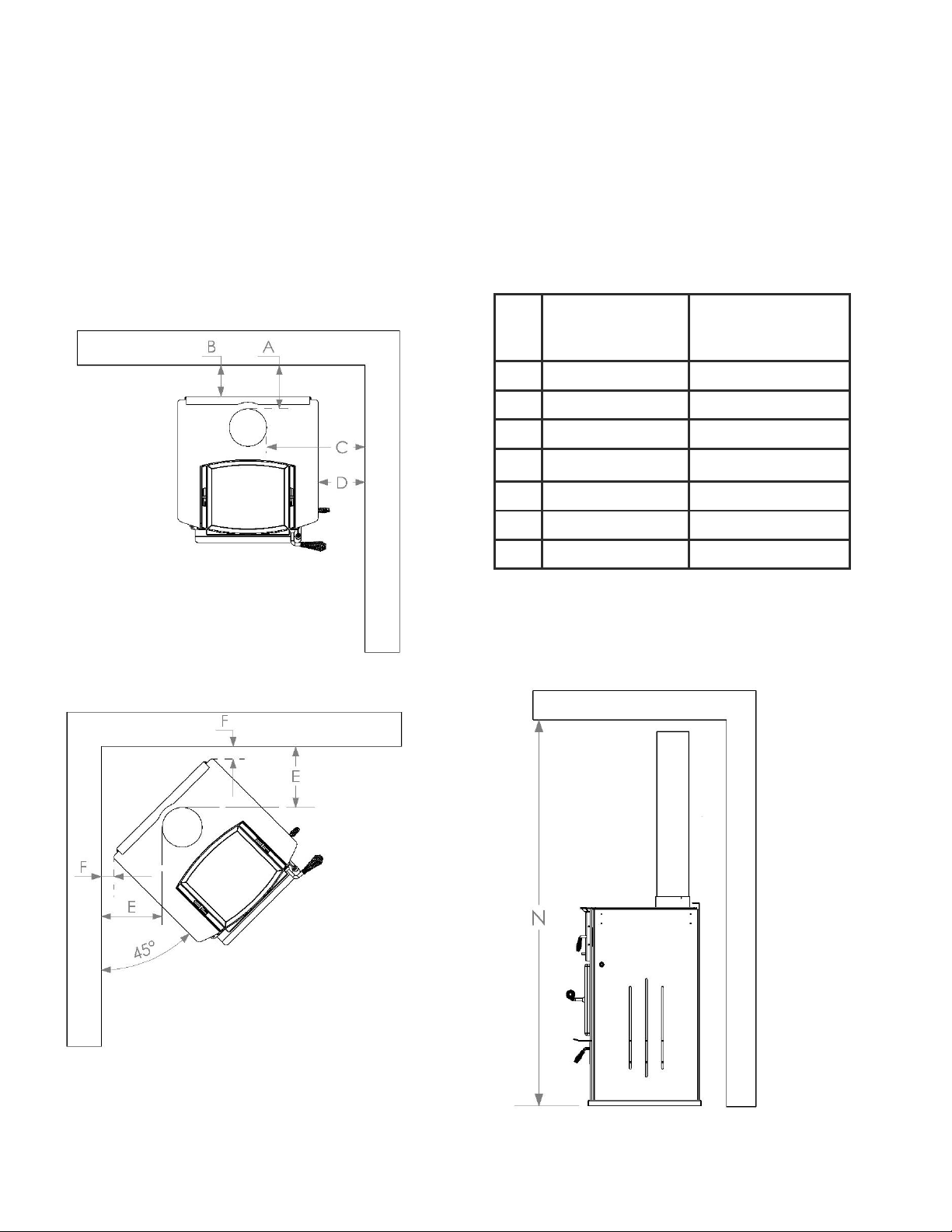
NOTE ALL MINIMUM CLEARANCE REQUIREMENTS TO COMBUSTIBLES. Installation must comply with
minimum clearances as listed in this manual. Clearances may only be reduced by means approved by the
regulatory authority.
Do not operate this stove with the door in an open position, except for cracking open during start-up. Continued
operation with the door open can cause overheating of the unit, and expose embers to nearby combustibles.
Do not operate with broken glass. Do not abuse glass such as striking or slamming the door.
This stove must be connected to a minimum 6” diameter listed chimney that complies with U.L. type 103HT
factory built chimney or a code approved masonry chimney. When installing into masonry chimneys, a U.L. 1777
approved liner must be installed. TO BE IN-STALLED AS A FREESTANDING COOK STOVE WITH THE
CLEARANCES IN THE MANUFACTURER'S INSTALLATION INSTRUCTIONS. NOT TO BE INSTALLED IN ANY
FACTORY-BUILT FIREPLACE.
When connecting single wall or double wall connector pipe to the stove and chimney, use 3 screws per pipe joint
including 3 screws securing the pipe to the stove. Depending on the type of double wall pipe you are using, it may
also be necessary to fasten it at the chimney.
Use only approved components for Chimney and Connector. Field fabricated or “makeshift” components are not
allowed and can cause a fire.
When connecting this stove to a masonry chimney, make sure you observe all applicable clearances including
walls, ceilings and other combustible material. A masonry chimney must be minimum 6” diameter and
constructed with a liner according to NFPA code 211. If you have any questions about the condition or the code
compliance of your masonry chimney, please speak with a qualified professional.
HOT WHILE IN OPERATION. KEEP CHILDREN, CLOTHING AND FURNITURE AWAY. CONTACT MAY CAUSE
SKIN BURNS.
DO NOT PUT WOOD OR ANY COMBUSTIMBLE MATERIAL IN THE STORAGE AREA UNDER THE
STOVE.

5
SECTION 2 - SPECIFICATIONS
CERTIFICATION TAG

6
APPLEWOOD DIMENSIONAL DRAWINGS
All dimensions are in inches.
Cookware Storage:
Do not store wood
here.

7
MINIMUM CLEARANCE REQUIREMENTS
Pipe clearances are measured to the outside diameter of the pipe. Stove clearances are measured to the top
plate of the stove. Pipe diameter will vary by brand so when planning your installation, make sure the stove
clearances AND the pipe clearances are equal to or greater than the minimum clearances. Always follow
local building codes. These clearances may be reduced only by using approved methods found in NFPA 211.
If you are installing the optional side shelves, all clearances to the stove remain the same as measured to the
top plate of the stove. You cannot install the stove at minimum corner clearance with the side shelves
attached: this is a physical impossibility. The side shelves can be installed with zero clearance to the walls.
*any ceiling height lower than 72” is considered an alcove
installation, see alcove requirements below.
Minimum
Clearance with
single-wall pipe
Minimum clearance
with double-wall
pipe
A
7
6.5
B
5
5
C
15.75
15.25
D
7.5
7.5
E
9.75
9.25
F
2
2
N*
84
72

8
ADDITIONAL CLEARANCE REQUIREMENTS FOR ALCOVE INSTALLATIONS
Minimum
Clearance with
single-wall pipe
Minimum clearance
with double-wall
pipe
B
Not Allowed: Must
use double wall for
alcove installation
5
L
12
12
M
Not Allowed: Must
use double wall for
alcove installation
38
P
Not Allowed: Must
use double wall for
alcove installation
60
(72 if wall exit)
R
18
Follow pipe
manufacturer’s
instructions.
Side view of wall exit Installation
Side view of Alcove Installation
Front View of Alcove Installation
ADDITIONAL CLEARANCE REQUIREMENTS FOR WALL EXIT INSTALLATIONS

9
SECTION 3 –INSTALLATION INSTRUCTIONS
FLOOR PROTECTION REQUIREMENTS
Floor protection must be non-combustible. Floor protection must be underneath the stove and extend to the
sides and front of the stove as shown below. Side protection (G) is measured to the top plate of the stove.
Front protection (H) is measured to the firebox face of the stove.
G
H
Type
3.25”
16”
Type 1 (ember protection) No insulation R-value required.
*Through Wall Installations: Hearth must extend underneath and 2” to either side of the horizontal
connector pipe.
It is highly recommended that this stove is installed by a qualified professional certified by the
National Fireplace Institute.
The structural integrity of the floor, walls and ceiling/roof must be maintained. Use additional
bracing if required. Never cut a load bearing wall or engineered truss.
NEVER INSTALL A STOVE IN A SLEEPING ROOM
This stove is heavy: Get help from another person and use proper lifting techniques
*

10
STOVE ASSEMBLY
Your stove comes almost fully assembled and screwed down to the wooden shipping crate. Using a 5/16”
socket wrench, remove the 4 screws from base of the stove. Place the stove onto your hearth taking care not
to scratch the hearth. Open the box located in the base of the stove and complete the assembly as follows:
Place the rear shield on the bottom of the oven at
the back. The shield fits between the side wall of the
oven with the flanges facing down.
Place the front sliding heat shield on the bottom of
the oven at the front. Orient the 2 square cut-outs
towards the front of the oven. You can then use the
oven tool to slide the shield forward and backwards.
Slide the shield all the way to the front of the oven
for baking and home heating. Slide the shield
backwards to expose the high-heat zone of the oven
for boiling or frying.
Slide the rear rack to the back of the oven on the
lower oven rail. You can move the racks to the upper
rail anytime that you would like.

11
Slide the front rack onto the lower oven rail (in front
of the rear rack). You can move the racks to the
upper rail anytime that you would like.
Your oven thermometer needs to stay outside the
oven unless you are baking. When baking, place the
thermometer in the circle cut-out of the front rack.
When you are not baking, there is a knock-out on
the back left corner of the stovetop that is designed
to store the thermometer. remove this knock-out
with a screwdriver and hammer if you would like to
use this location. Otherwise, the thermometer can
be stored below the oven or placed anywhere on the
cooktop to gauge the temperature of the griddle
area. The oven area can get very hot when not
baking: Do not exceed 550° oven temperature
with the thermometer in the oven: The
thermometer will discolor and become difficult to
read.
Place the griddle on the top of the oven. The griddle
can also be slid down onto the oven rails to move it
closer to the heat.
The griddle, racks and front heat shield can be
removed to expose the high heat boiling zone of the
stove.
Configure the stove prior to starting a fire so that
you do not have to handle these components while
hot. See section 5 for more information on
cooking with the stove.
Thermometer Storage area

12
If you are installing the optional side shelves,
follow the instructions that come with the shelves
prior to installing the tool hook.
There are threaded holes provided to install the tool
hook on the left side of the stove at either the front
or the back corner. Use the bolts provided and a
7/16” wrench to install the tool hook. Firmly press
the small decorative rivet caps into the remaining 6
holes.
Hang the oven tool on the hook.
The grill plate is used for grilling over hot coals
inside the firebox of the stove. To use the grill plate,
place the 2 bricks against the sides of the firebox as
shown. Build a fire and let it burn down to hot coals
then place the plate on top of the bricks.
It is recommended that you build a fire between the
bricks before placing the plate and grilling.
ALWAYS CLOSE THE DOOR WHEN NOT
ACTIVELY TENDING YOUR FIRE. DO NOT LEAVE
THE DOOR OPEN ON THE STOVE.
Remove the grill plate and bricks when not using.

13
SAFETY STANDARDS
The safety standards referenced in this manual are easy to find online. Products that meet these standards
will be readily available from your dealer. Refer to this glossary of terms for a better understanding of these
standards:
INTAKE AIR REQUIREMENTS
There is a 4” round opening on the back panel that draws in the combustion air for the stove. The simplest air
intake method is to let the stove draw in air from the room through the 4” round opening. If you are installing
an outside air connection to the stove, use the outside air kit (KA-OA-1) to pipe air to the back of the stove
ash shown below:
Standard
Description
UL 103
Covers the safety requirements for factory-built (metal) chimneys that vent wood stoves.
Chimney manufacturers can either comply with a 1700° or a 2100° flue-gas temperature
test.
UL 103HT
Chimney manufacturers that choose to comply with the 2100° flue-gas temperature test
will receive the designation of a 103HT chimney system. HT stands for High Temperature.
Virtually all modern wood stoves will require this type of chimney.
UL 1777
Covers the safety requirements for chimney liners that are installed into masonry
chimneys. Your chimney liner will meet the safety requirements of UL 1777 only if the
installation instructions for the liner are followed.
NFPA 211
A publication put out by the National Fire Protection Association that details the proper
installation of wood stoves, chimneys, fireplaces, and venting systems.

14
CHIMNEY AND CONNECTOR PIPE REQUIREMENTS
A properly installed and maintained venting system is critical to the safe operation of your wood stove. This
stove may be connected to a 6” inside diameter factory built all fuel chimney system that has been safety
tested to the UL-103HT standard. This stove may also be connected to a lined masonry chimney that meets
the standards of NFPA 211.
If you are choosing the location to install a new chimney, decide on a central location in the main living area
of the home. Uninhabited areas of the home such as an uninsulated basement or a garage would be an
inefficient location for the stove. Also consider not placing the chimney too close to your neighbors or in a
valley that would cause a nuisance or unhealthy outdoor air quality. For proper draft, the chimney must exit
the roof a minimum of 3 feet and at least 2 feet above any portion of the roof that is within 10 feet of the
chimney.
Minimum Flue Height Recommendations
No offsets in the chimney
14 ft
30° or 45° offsets in the chimney
15 ft
90° offsets in the chimney
16 ft.
90° offsets with 2-3 feet of horizontal run
20 ft.
90° offsets into exterior chimney
22 ft.
CONNECTOR PIPE
The connector pipe is the portion of the venting system that connects the stove to the chimney system. This
is the portion of the venting system that is always visible from inside the home. The connector pipe must be
24ga. single wall black stove pipe or a listed double wall connector pipe. Connector pipe must be secured with
3 screws at each joint. Listed double wall connector pipe is required for mobile home installation and is
recommended for all installations to improve the draft performance of the stove. It is recommended that you
install a telescoping or slip connection near the stove to give easy access for cleaning the chimney and stove.
If a slip connection is not practical, it is recommended to install a double wall tee near the stove to give easy
access for cleaning the chimney and stove.
WHEN CONNECTING TO AN ALL-FUEL CHIMNEY SYSTEM
For complete installation instructions, carefully follow the installation manual that came with your
all fuel chimney system.
Your chimney must meet the UL-103HT standard. Do not mix different brands of chimney parts.
Do not use connector pipe to pass through an attic, closet, wall, floor or ceiling.
Use only prefabricated listed chimney and connector pipe. Field fabricated or “makeshift” parts
could result in a chimney or house fire.
Inspect all chimney parts for damage. Do not use any damaged chimney parts

15
An all-fuel chimney system consists of prefabricated metal chimney parts that have been designed and tested
for use with modern wood stoves. Examples of 103 HT chimney systems include:
•DuraTech manufactured by DuraVent
•Excel manufactured by ICC Chimney
•Ultra Temp manufactured by Selkirk
•Temp/Guard manufactured by Metal-Fab
When choosing a location for your chimney you will need to study the clearance requirements for both the
stove and the chimney. Many chimney systems require a 2” air space around the pipe. Refer to the
clearance diagrams in section 2 for minimum clearances around this stove. You will need to install
supports, braces, shielding and firestops according to the chimney manufacturer’s recommendations. When
passing the chimney through an attic space an insulation shield must be used to ensure that no insulation can
contact the chimney. For safety, the chimney must penetrate the roof a minimum of 3 feet AND must be at
least 2 feet higher than any part of the roof that is within 10 feet of the chimney. For proper draft, the venting
system (chimney + connector pipe) should be at least 14 feet from the stove top to the venting cap. If you live
in a snowy region and you have a metal roof, consider adding snow breaks or diverters to your roof to prevent
damage from sliding snow and ice. Scan to see the Kuma snow diverter engineered for metal roofs:
ADDITIONAL REQUIREMENTS FOR MANUFACTURED (MOBILE) HOMES
An outside air kit (KA OA 1) is required for all mobile home installations. Follow the instructions
located in the box.
A double wall connector pipe is required for all mobile homes.
Using 8-gauge ground wire and appropriate connectors, you must drill through the hearth and
connect the stove to the metal frame underneath the mobile home.
When required by local code, you will need to fasten the stove to the floor of the mobile home.
CAUTION: The structual integrity of the mobile home floor, wall and ceiling/roof must be
maintained.
WARNING: Do not install in a sleeping room of a mobile home.

16
Typical installation of an all-fuel chimney system
Spark arrestor
cap
10’
Roof brace
Residential or
manufactured home
Installation
Residential Home
Installation
Storm collar
Chimney
Sections
Attic
Insulation
Shield
Support
Box
Cross Framing
Double
Wall
Connector
4” outside air vent
2” MINIMUM
air space around
chimney
2” MINIMUM
air space around
chimney
Tee Support
Chimney
Tee with
cleanout
Wall Thimble
with horizontal
chimney
section must
extend 5”
minimum into
room.
Double Wall
Connector
ATTIC
4” outside
air vent
Wall support
Flashing

17
WHEN CONNECTING TO A MASONRY CHIMNEY
Your masonry chimney must be built according to an approved method of construction such as the NFPA 211
standard. Visit nfpa.org for free access to the standard.
1. Have a certified chimney inspector clean and inspect your chimney to make sure that there are no
code violations, cracks, damaged mortar joints, or blockages. If your chimney is damage or does not
meet code requirements, you may need to re-line or re-build your chimney.
2. Install a flue liner that meets the type HT requirements (2100°) per the UL 1777 standard.
3. Kuma recommends that an insulated chimney liner always be installed into a masonry chimney for
improved performance and ease of cleaning. Chimney liners should not be smaller than 6” diameter or
the equivalent cross-sectional area of 28 square inches. Any reduction in flue size may result in
smoking or poor performance.
4. Equally important to the construction of the chimney is the connection between the stove and the
chimney. When passing through a combustible wall, use the following diagram to make sure that it is
a safe method:
WHEN PENETRATING A COMBUSTIBLE WALL TO CONNECT TO A MASONRY CHIMNEY YOU
MUST BE CERTAIN THAT THE WALL PASS THROUGH IS A SAFE AND CODE APPROVED
METHOD such as the NFPA 211 standard. See Figure 6-7.5 from the NFPA 211-2016, Standard for
Chimneys below

18
Reprinted with permission from NFPA 211-2016, Standard for Chimneys, Fireplaces, Vents, and Solid Fuel-Burning Appliances, Copyright © 2015,
National Fire Protection Association, Quincy, MA. This reprinted material is not the complete and official position of the NFPA on the referenced
subject, which is represented only by the standard in its entirety which may be obtained through the NFPA website at www.nfpa.or

SECTION 4 - OPERATING INSTRUCTIONS
YOUR 1ST FIRE (BREAK-IN PERIOD)
Paint Curing: When building your 1st fire, be careful to start small and increase the heat slowly over a 4 to 5-
hour period. The paint on the stove cures with heat and needs to be done slowly. As the paint cures, it gives
off a smell and even sometimes a visible haze into the room. Do not use the oven for baking until you have
fully cured your stove paint for at least 5 hours. Make sure the area is well ventilated during the curing
operation. The smell will subside after a few hours of operation.
Popping and creaking: As the metal heats up and cools down, it moves. This movement can cause a normal
popping or creaking sound that will likely decrease after the first several weeks.
Performance: It is normal for the first few fires to seem a bit lazy. As moisture evaporates from the brick, the
fire will become more active. A layer of ash in the bottom of the stove will also help to keep your coal bed hot
and active. A good thick coal bed and full load of dry wood are key to optimum performance.
SELECTING WOOD
The leading cause for creosote build-up in the stove or chimney is moisture in the wood. Wood should be
protected from rain and seasoned for 1 full year prior to being used. Your wood must have a moisture content
of 15% or less. You will need to use a moisture meter to determine the moisture content of the wood. The
recommended wood length for this stove is 14”. This stove is designed to burn natural wood only. Higher
efficiencies and lower emissions generally result when burning air dried seasoned hardwoods, as compared to
softwoods or to green or freshly cut hardwoods. Be mindful of what you are burning if you choose to cook
inside the firebox of the stove. For example, you do not want to use an alcohol based Firestarter or creosote
removing products before or during a fire that you cook over.
DO NOT BURN:
•Lawn clippings or yard waste
•Garbage, manure or animal remains
•Plastic or materials containing rubber, including tires
•Waste petroleum products, paints or paint thinners, or asphalt products
•Materials containing asbestos
•Construction or demolition debris including railroad ties or pressure-treated wood
•Saltwater driftwood or other previously salt water saturated materials
•Unseasoned wood; or Paper products, cardboard, plywood, or particleboard
Burning these materials may result in release of toxic fumes or render the cook stove ineffective and cause
smoke. You may use fire starters made from paper, cardboard, saw dust, wax and similar substances.
NEVER USE FLAMMABLE LIQUIDS TO START OR FRESHEN UP A FIRE
CAUTION: Do not use any fuels that are not seasoned natural wood.
Do not leave the stove unattended with the door open.
DO NOT OVERFIRE THIS STOVE –Attempts to achieve temperatures that exceed this stove’s
design specifications can result in permanent damage to the stove.

20
LIGHTING A FIRE
Step 1: Slide the air control out away from the stove
until it stops. The air is now fully open for starting a
fire.
DO NOT STORE WOOD OR COMBUSTIBLE
MATERIALS UNDERNEATH THE ASH PAN. THIS
AREA IS FOR COOKWARE STORAGE
Step 2: Open the door and place kindling, Firestarter,
and small pieces of wood in the stove. Do not use a
grate or elevate the fire –Build the fire directly on the
fire brick. When starting a fire, you should never use
un-split pieces of wood unless they are small, such as
twigs and branches.
Shown to the right is an example of what is called a
“top down” fire: Start by loading larger pieces of wood
into the firebox bottom then stack progressively
smaller pieces so that the kindling pieces are at the top
of the stack. You may use a fire starter such as
shredded paper on top of the kindling.
Table of contents
Popular Cooker manuals by other brands

Zanussi
Zanussi N 900 Specifications

Moffat
Moffat U04259 Instruction book

Smeg
Smeg BG91IX2 Translation of the original instructions

Zanussi
Zanussi ZE 942 Instructions for the use and care

Creda
Creda HB49127 Instruction and recipe book

Blue Seal
Blue Seal Evolution series G47 Installation and operation manual