KYOWA EDS-450A User manual

IM-A-575d October 2005
EDS-400A SERIES
COMPACT RECORDER
INSTRUCTION MANUAL
FOR HARDWARE
Thank you for purchasing a product of KYOWA ELECTRONIC
INSTRUMENTS.
Please read this manual carefully to ensure the long life and reliability
of the product.
The product should not be used in any manner other than as described
in this manual.
This manual covers only the hardware operating instructions.
For details of the Software, please refer to the “Instruction Manual for
Software.”
Windows 2000/XP is a trademark of Microsoft Corporation.
The company names and product names mentioned in this manual are generally the trademarks or registered
trademarks owned by the respective companies.
All rights reserved. Copying or reproduction of this product, whether in part or whole, is expressly prohibited
without permission.
This product is a copyrighted work of KYOWA ELECTRONIC INSTRUMENTS Co., Ltd. All rights
reserved.
The contents of this manual are subject to change without prior notice.

CONTENTS
STANDARD ACCESSORIES..............................................................................................................................1
OPTIONAL ACCESSORIES...............................................................................................................................1
SAFETY PRECAUTIONS (Be sure to read the safety precautions prior to use.)..........................................2
PRIOR TO USE ....................................................................................................................................................................2
SAFETY SYMBOLS............................................................................................................................................................2
NOTATIONS USED IN THIS INSTRUCTION MANUAL .............................................................................4
OPERATING KEYS, MENU OPTIONS AND SET OR SELECTED ITEMS....................................................................4
PRECAUTIONS ...................................................................................................................................................................4
ESSENTIAL PRECAUTIONS FOR USE OF THE PRODUCT..........................................................................................5
INITIAL SETTINGS FOR LAN ..........................................................................................................................................6
1 PRODUCT OVERVIEW...................................................................................................................................7
1-1 OVERVIEW ...................................................................................................................................................................7
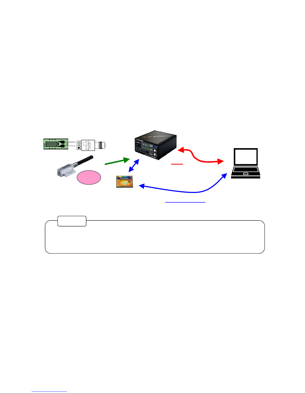
1-2 SYSTEM CONFIGURATION .......................................................................................................................................8
2 NOMENCLATURE AND MAIN FUNCTIONS.............................................................................................9
2-1 FRONT ...........................................................................................................................................................................9
2-2 REAR............................................................................................................................................................................12
3 CONNECTIONS ..............................................................................................................................................14
3-1 CONNECTING A POWER SUPPLY ..........................................................................................................................14
3-1-1 Connecting Method ................................................................................................................................................14
3-1-2 Pin Assignments.....................................................................................................................................................14
3-2 CONNECTING INPUT CONNECTORS ....................................................................................................................15
3-2-1 Inputting Strain.......................................................................................................................................................15
3-2-2 Inputting Voltage....................................................................................................................................................16
3-3 CONNECTING MULTIPLE EDS-400AS (ONLY EDS-400A)..................................................................................17
3-3-1 Connecting "CONT. IN" (Only EDS-400A).......................................................................................................... 18
3-3-2 Connecting "CONT. OUT" (Only EDS-400A) ......................................................................................................18
3-4 CONNECTING THE PC .............................................................................................................................................. 19
3-4-1 Connecting the EDS-400A (or EDS-450A) Directly to the PC..............................................................................19
3-4-2 Connecting the EDS-400A to the PC via a Hub.....................................................................................................19
3-5 CONNECTING EXTERNAL CONTROL SIGNALS (Only EDS-400A)...................................................................20
3-6 TURNING THE POWER ON/OFF..............................................................................................................................21
4 OPERATING PROCEDURES .......................................................................................................................22
4-1 FLOW OF OPERATION WHEN ONE EDS-400A (OR EDS-450A) IS USED ......................................................... 22
4-2 FLOW OF OPERATION WHEN MULTIPLE UNITS ARE USED (ONLY EDS-400A)..........................................26
5 TROUBLESHOOTING...................................................................................................................................31
6 TECHNICAL INFORMATION.....................................................................................................................32
6-1 DATA FILE NAME .....................................................................................................................................................32
6-2 INITIALIZATION........................................................................................................................................................32
6-3 RECORDING TIME WITH 128-MB CF CARD (REFERENCE)...............................................................................33

7 SPECIFICATIONS..........................................................................................................................................34
7-1 OVERALL SPECIFICATIONS ...................................................................................................................................34
7-2 HARDWARE SPECIFICATIONS...............................................................................................................................34
7-3 EXTERNAL VIEW ......................................................................................................................................................36

1
STANDARD ACCESSORIES
The following accessories are enclosed with EDS-400A Series EDS-400A/EDS-450A Compact Recorder.
After unpacking, check the contents to ensure that all accessories are enclosed:
DC power cable (P-57: 2 m) ................................................................................................................... 1
Attachable rubber foot ............................................................................................................................ 1
Compact flash memory card (128 MB) .................................................................................................. 1
CD-R (EDS-40A Control Software, Instruction Manual) ...................................................................... 1
Inspection Report .................................................................................................................................... 1
Warranty ................................................................................................................................................. 1
OPTIONAL ACCESSORIES
Strain input cable : U-49 (R05-NDIS Standard Connector, 30 cm)
Voltage input cable : U-50 (R05-BNC, 1.5 m)
Sync cable : N-79 (20 cm)
AC adapter : SA-10A-EDS (100 to 240 VAC)
Remote-control unit : RCU-04A
Data Analysis Software : DAS-100A

2
SAFETY PRECAUTIONS (Be sure to read the safety precautions prior to use.)
PRIOR TO USE
For safe use of the EDS-400A (EDS-450A), be sure to read the safety precautions described below.
KYOWA ELECTRONIC INSTRUMENTS CO., LTD. assumes no liability for any damage resulting from
the user's failure to comply with the safety precautions.
SAFETY SYMBOLS
For safety operation of the EDS-400A (or EDS-450A), the following “WARNING” and “CAUTION”
symbols are used in SAFETY PRECAUTIONS of this manual and indicated on the product.
△
!WARNING
Improper operation of the system may result in severe injury or death of the
operator.
△
!CAUTION
Improper operation of the system may result in injury to the operator and physical
damage to the system.
△
!WARNING
●Power supply
To prevent fire hazards, ensure that the power supply voltage specified for the EDS-400A (or EDS-
450A) (10 to 16 VDC) matches the local line voltage before connecting the system to the DC power
supply.
●Inflammable Environment
To prevent the risk of fire and explosion, do not operate the EDS-400A (or EDS-450A) in an area
exposed to flammable gases, vapors or dust.
●Abnormal Condition
To prevent fire hazards, if smoke is emitted from the EDS-400A (or EDS-450A), turn OFF the power
switch immediately, disconnect the power cable from the power supply and stop using the instruments.
●Measurement Under High Voltage
Do not measure a target charged with high voltage. It may reduce the performance of the system or
cause a system failure.

3
△
!CAUTION
●After turning off the system power, wait at least five seconds before turning on the power again.
If the system power is turned on within five seconds of power-off, or if the system power is turned on
and off repeatedly in quick succession, a system failure may occur due to the rush current generated
upon power input.
●Use the EDS-400A (or EDS-450A) in a temperature range of 0 to 50°C.
Using the EDS-400A (or EDS-450A) outside the specified operating temperature range may diminish
the system's performance or cause a failure.
If the EDS-400A (or EDS-450A) must be used under direct sunlight or in a cold place, provide a
sunshade or keep the operating area warm.
●Use the EDS-400A (or EDS-450A) within a relative humidity range of 20% to 90%.
Using the EDS-400A (or EDS-450A) in an environment exceeding the operating humidity range or in
an area exposed to splashing water may diminish the system’s performance or cause a failure.
●Do not use the EDS-400A (or EDS-450A) immediately after an abrupt change in the environment.
Leave the EDS-400A (or EDS-450A) in the operating environment until it is adapted to the change
prior to use.
An abrupt change in ambient temperature and humidity occurring through transport of the system or
other reason may cause dew condensation, which could in turn diminish the system's performance or
cause a failure.
●Do not use the EDS-400A (or EDS-450A) in an environment that is subject to significant amounts of
dust.
If dust should enter the internal mechanism, a system failure may occur due to poor connector contact,
reduced insulation, etc. Prevent dust intrusion not only when the EDS-400A (or EDS-450A) is
operating but also when it is in storage.
●Do not use the EDS-400A (or EDS-450A) in an area that is subject to significant vibration or impact.
If the EDS-400A is subjected to strong vibration or severe impact, a system failure may result.
●Do not use the EDS-400A (or EDS-450A) in an area that is subject to a strong magnetic field.
Use the EDS-400A (or EDS-450A) in an environment where the magnetic field is acceptable for use of the
PC.
Using the EDS-400A (or EDS-450A) near a radio transmitter/receiver, microwave oven, electric furnace or
any other equipment that generates a strong magnetic field may diminish the system's performance or cause
a failure.
●Use the EDS-400A (or EDS-450A) with a power supply of the specified voltage range.
The power supply should be able to provide 10 to 16 VDC and be free of momentary power failure or
noise.
●Do not pull directly on the connector cables.
When routing the connector cables, provide a margin for the length so that no excessive force will be
applied to the cable connections. Pulling the cable or applying excessive force may cause a system
failure or interruption of the measurement process.
●Take proper precautions when handling the CD-R.
Do not store the CD-R under direct sunlight or in a hot or humid place.
Do not put any object on the disc, bend the disc, or otherwise apply force to it.
Handle the disc carefully so as not to leave fingerprints, stains or scratches on either side.
●Do not disassemble or modify the EDS-400A (or EDS-450A).
Do not attempt to disassemble or modify the EDS-400A (or EDS-450A) since inappropriate
disassembly or modification by the user may result in electric shock or system failure.
●Do not insert a foreign object into the slot for the Compact flash memory card.
Inserting a foreign object into the slot for the Compact flash memory card (hereinafter referred to as
CF card) may cause a system failure.
●Warm the EDS-400A (or EDS-450A) prior to use.
Wait around 30 minutes following power-up for pre-heating, in order to measure accurately.

4
The information provided is useful as a reference.
MEMO
NOTATIONS USED IN THIS INSTRUCTION MANUAL
OPERATING KEYS, MENU OPTIONS AND SET OR SELECTED ITEMS
Operating panel keys are expressed in “.” (quotation marks).
PRECAUTIONS
Certain notations are used as necessary to urge the reader's attention to information that requires special
attention in the handling of the system, and to information provided for reference purposes.
Examples of Notations
The information provided merits special attention in the handling of the system.
NOTE

5
ESSENTIAL PRECAUTIONS FOR USE OF THE PRODUCT
1. Never turn OFF the power during data recording.
Turning OFF the power of the EDS-400A (or EDS-450A) during data recording will damage
the current recording data and null the data resulting to create a size 0 file.
In some instances, data in the CF card or the card itself may be damaged.
2. Never turn OFF the power while collecting data through LAN.
Or, data in the CF card or the data itself may be damaged.
When collecting data through LAN, since you cannot visually check whether it is actually
collecting data, check to be sure that it is not collecting data using the Control Software and
then, turn OFF the power.
3. If power failure is likely to occur, always use an uninterruptible power supply unit.
4. When using an external battery, use the battery with enough capacity to satisfy the
measurement time. Consumption current of the EDS-400A (or EDS-450A) is approximately
0.6 A when 12 VDC is supplied.
5. Before recording data, always install the CF card in the card slot of the EDS-400A (or EDS-
450A). Or, no data recording is started.
6. Do not forget to turn OFF the power before ejecting the CF card from the card slot of the EDS-
400A (or EDS-450A)
When the power is turned ON, the EDS-400A (or EDS-450A) may be currently accessing the
CF card for recording data or collecting data through LAN. If the CF card is ejected at this
time, data in the CF card or the CF card itself is likely to be damaged. Therefore, before
ejecting the CF card, check to be sure that the EDS-400A (or EDS-450A) is not operating an
d
then, turn OFF the power.
7. Use CF card with a processing speed of x 45 or higher.
Using a CF card with a processing speed below x 45 may stop recording data, depending on
the sampling speed.
8. If multiple EDS-400As are used, be sure to use preformatted CF cards of the same type an
d
capacity. The use of CF cards of varying types and capacities will create discrepancies in the
writing speeds of the cards, which affects synchronization at the start of data recording.
9. When formatting the CF card, never make the Volume Label “blank.”
10. To record more than 169 data files into the CF card, it is required to format the CF card with
“FAT32.”
11. The EDS-400A (or EDS-450A) is provided with a real-time clock function. Clock data is
backed up for approximately 8 hours*1. If the system power has been turned OFF for 8 hours o
r
more, the built-in clock will not display the correct time the next time the EDS-400A (or EDS-
450A) is started. If the measurement requires clock information, connect the EDS-400A (o
r
EDS-450A) to the PC and establish “LAN connection” using the bundled Control Software.
The moment a certain data is transferred between the EDS-400A (or EDS-450A) and the PC,
the PC's clock information is automatically set in the EDS-400A (or EDS-450A).
*1:When the EDS-400A (or EDS-450A) is continuously powered for more than 4 ours.
[Reference] Setting conditions other than the time; such as the range, sampling frequency,
zero suppression data, etc. are recorded in the non-volatile memory of the EDS-
400A (or EDS-450A), so they will not be lost semi-permanently.
NOTE

6
The procedure used to revert the LAN settings to the initial settings is described in Chapter 6,
"TECHNICAL INFORMATION" and in 6-2, "INITIALIZATION," of this manual.
MEMO
INITIAL SETTINGS FOR LAN
The initial settings (factory settings) for the local area network are as follows:
System ID 0 (Master)
IP address 192 . 168 . 0 . 1
Gateway 0 . 0 . 0 . 0
Subnet mask 255 . 255 . 255 . 0

7
1 PRODUCT OVERVIEW
1-1 OVERVIEW
The EDS-400A Series EDS-400A/EDS-450A is a strain/voltage recorder designed for use in combination
with PC. It can be used in various applications, including vehicle onboard measurement
The user can set conditions for recording, perform zero suppression*1, start/stop measurement and collect
data from the PC connected to the EDS-400A (or EDS-450A) via LAN. These operations can also be
performed via the panel screen switches or by using a CF card*2 without the need to connect a PC.
The EDS-400A is capable of measuring the maximum of 32 channels by connecting up to eight EDS-400A
units (each EDS-400A can measure 4 channels). Therefore, it is possible to configure systems for
applications ranging from simple testing to advanced measurement.
The EDS-450A is solely used for measuring 4 channels.
Zero suppression*1: This term means zero balance in the strain input mode, or the function used to
shift the input voltage to 0 V in the voltage input mode.
CF card*2: Compact flash memory card
MEMO
Strain gage
Strain gage type
transducer
Voltage
Connect
Set
Replace CF card
Collect data
LAN
Set
Monitor
Collect data
Dedicated software
Bridge Box
CF card

8
Four input (sensor) 4 channels:
Strain gages (4-gage method), strain gage type transducer (120 to 1000 Ω) and
voltage (within ±20 V)
Re
g
ardin
g
connection with PC
,
refer to “3-4 CONNECTING THE PC”.
Power supply:
10 to 16 VDC,
approx. 0.6 A
Control software
LAN cable
Install
PC:
WindowsXP/2000
Memory: 256 MB or more
1-2 SYSTEM CONFIGURATION
PC: Use a PC equipped with a LAN interface.
The following minimum specifications are recommended:
CPU: Pentium III 700 MHz or equivalent, or faster
OS: English-version WindowsXP/2000
Memory: 256 MB or more
Hard-disk drive: 10 MB or more of free disk space (excluding space for
storage of measured data)
Display: Resolution 1024 × 768 dots or higher
Display colors: Full-color
LAN interface: 10BASE-T/100BASE-TX
CD-ROM drive: Used for installation of Control Software, etc.
DC power supply: Power supply of 10 to 16 VDC required
Current consumption is approximately 0.6 A (when 12 VDC is supplied).
LAN cable: Use a cross cable when the connecting the EDS-400A (EDS-450A) directly to the
PC, or a straight cable when connecting it to a PC via a hub.
Regarding connection with PC, refer to “3-4 CONNECTING THE PC”.
LAN hub: Purchase a LAN hub, as necessary, if multiple EDS-400As are to be used.
Control Software: To be installed on the PC for use.
The rear of EDS-400A

9
2 NOMENCLATURE AND MAIN FUNCTIONS
2-1 FRONT
EDS-400A
EDS-450A
1) 2) 3)4) 5) 6) 7)
10) 9) 8)
1) 2) 3) 4) 5) 6) 7)
10) 9) 8)

10
1) "POWER" switch System power is turned OFF when this switch is slid to the "{"
position or ON when slid to the "|" position. When the EDS-400A
power is ON, the “POWER” switch lights up green.
2) "SYNC" lamp This lamp indicates the status of synchronization.
Steady green light: The system is set as the master.
Steady orange light: The system is set as a slave and is not
receiving the sync signal.
Flashing orange light: The system is set as a slave and is
receiving the sync signal.
3) "MEAS." lamp This lamp indicates the status of data recording.
Steady green light: Master – Recording data
Slave – Waiting for the sync signal
Flashing green light: Master – Waiting to be triggered
Steady red light: The lamp remains lit in red after a start
signal is received until recording data is
actually started.
Flashing red light: A data recording error has occurred.
Off: Data recording is stopped.
4) "1," "2," "3" and "4" lamps These lamps indicate the zero-suppression setting status and the
input status of each channel.
Steady green light: The result of zero suppression is normal.
Steady orange light: A signal exceeding the set range was
input during recording data. The lamp
will remain lit in orange until recording
data is started again or zero suppression
is implemented.
Flashing red light: Result of zero suppression is abnormal.
Off: The range setting or zero suppression is
set OFF.
Turns off momentarily: Zero suppression is in progress.
5) "START/STOP" switch Pressing this switch while recording data is stopped will start
recording.
Pressing it during recording will stop recording.
6) "ZERO" switch Pressing this switch will implement zero suppression on the
channels for which zero suppression is enabled. This switch is
invalid during recording.
7) "READ" switch To set the conditions for recording, place in the card slot 10) a CF
card containing recording conditions and then press this switch.
The EDS-450A is used only as a master unit and not as a slave unit.
NOTE

11
8) "READ" lamp This lamp indicates the setting status of conditions when the
"READ" switch 7) is used to set the conditions for recording.
Steady green light: Recording conditions were set
successfully.
Flashing green light: The recording conditions are being read.
Flashing red light: An error occurred while reading the
conditions for recording.
Off: The recording conditions are not read,
or the conditions thus read were
subsequently changed via LAN
communication.
9) Card eject button Pressing this button once will cause the button to pop up.
Pressing the button again will eject the CF card. Insert a CF card
when the button is not popping up.
10) Card slot Install a CF card prior to recording.
Since the recorded data is directly written to the CF card, an
attempt to start recording without a card in the slot will generate
an error.

12
2-2 REAR
EDS-400A
EDS-450A
1)
2)5)
1)
2) 3) 4) 5)

13
1) "1," "2," "3" and "4" input connectors These connectors are used to input strain/voltage.
Connector type R05-R5F (Tajimi Electronics)
Applicable plug type R05-PB5M (Tajimi Electronics)
2) "LAN" connector This connector is used to connect a 10BASE-T/100BASE-TX
LAN cable.
Connector shape RJ-45 modular jack
3) "CONT. IN" connector (Only EDS-400A)
This “CONT IN” connector is used when multiple EDS-
400As are used by cascade connection, a remote-control unit
is connected or EDS-400A is controlled via external signals.
Cascade connection
Connect the "CONT. IN" on each EDS-400A to the
"CONT. OUT" connector on the previous unit via an
optional cascade cable.
Connection of remote-control unit
An optional remote-control unit can be connected to
start or stop the EDS-400A, or to implement zero
suppression.
External signal connection
External signal input can be used to start or stop the
EDS-400A, or to implement zero suppression.
4) "CONT. OUT" connector (Only EDS-400A)
When multiple EDS-400As are used, this "CONT. OUT"
connector is connected to the "CONT. IN" connector on the
next unit via an optional cascade cable.
△
!
5) "DC INPUT" connector This connector is used to supply 10 to 16 VDC power to the
EDS-400A (or EDS-450A) via the supplied DC power cable.
Connector type RM12BRD-4PH (Hirose Electric)
Applicable connector plug type
RM12BPG-4S (Hirose Electric)
△
!→Refer to 3-1.
To supply power to the EDS-400A (or EDS-450A) from 100
to 240 VAC power, use an AC adaptor (Optional).

14
+10~16 VDC
0 VDC
Red and White DC power cable
Black and Green
100~240 VAC
AC adapter
(Accessory)
3 CONNECTIONS
3-1 CONNECTING A POWER SUPPLY
△
!3-1-1 Connecting Method
Connect the supplied DC power cable to the power connector to supply 10 to 16 VDC.
Connect the negative side to the both black and green lead wires, and then connect the positive side to
the both red and white lead wires.
3-1-2 Pin Assignments
EDS-400A (or EDS-450A) side connector Type: RM12BRD-4PH Manufacturer: Hirose Electric
Cable connector Type: RM12BPG-4S Manufacturer: Hirose Electric
Pin No. Description of signal
1 +10 to 16 VDC input
2 +10 to 16 VDC input
3 0 VDC
4 0 VDC
«When an accessory DC power cable is used. »
«When an accessory AC adapter is used. »
●Check the supply voltage is in a range from 10 to 16 VDC before connecting the power supply.
●Connecting the power cable in reversed polarities or supplying excessive voltage may damage
the equipment. Exercise due caution.
NOTE

15
R05-PB5M
Bridge box
Optional accessory
Strain gage
3-2 CONNECTING INPUT CONNECTORS
The manufacturers and applicable types of input connectors are as follows:
EDS-400A (or EDS-450A) side connector Type: R05-R5F Manufacturer: Tajimi Electronics
Cable connector Type: R05-PB5M Manufacturer Tajimi Electronics
3-2-1 Inputting Strain
Use a 4-conductor shielded cable to connect a strain-gage transducer or strain-gage bridge according to
the pin numbers listed below.
(Cable colors conform to the representative color-coding system applied to Kyowa transducers.)
Pin No. Description of signal
A Positive side of bridge power supply (red lead wire)
B Negative side of bridge output (white lead wire)
C Negative side of bridge power supply (black lead wire)
D Positive side of bridge output (green lead wire)
E Shielded cable
«When input signals are directly hook up to the input connectors. »
●Wire the inputs using a four-pin shielded cable of minimal length.
●Keep the input cable as far as possible from power cables or other cables that are prone to
significant noise.
●When EDS-400A (or EDS-450A) is used at the place where vibrations are applied, use the
enough length of input cables and securely fix them, in order not to apply extra force to the
connected
p
ortion of the in
p
ut cables.
NOTE
Strain gage type transducer
Strain gages (4-gage bridge)
R05-PB5M type connector bridge box(Optional accessory)
DB-120C-2R 120Ω,1 gage 2 wire type bridge box
DB-120C-3R 120Ω,1 gage 3 wire type bridge box
MEMO

16
Strain input cable
U-49
(optional accessory)
Voltage signal
Voltage signal (-)
(D)
(B)
(E)
voltage input cable
U-50
(Optional accessory)
Voltage signal (+)
«When strain input cables are used.
3-2-2 Inputting Voltage
Connect voltage signals according to the pin numbers listed below.
The use of a shielded cable is recommended for the input of weak signals.
Pin No. Description of signal
A Not connected
B Input signal (negative side)
C Not connected
D Input signal (positive side)
E Input signal (negative side), shielded cable
«When input signals are directly hook up to the input connectors. »
«When voltage input cables are used. »
●When inputting voltage, be sure to connect pins B and E of the input connector.
●Keep the input cable as far away as possible from power cables or other cables that are prone
to significant noise.
●When the EDS-400A (or EDS-450A) is used at the place where vibration is applied , use the
input cable with enough length and securely fix them, in order not to apply extra force to the
connected
p
ortion of the in
p
ut cables.
NOTE
Strain gage type transducer
Bridge box
(NDIS standard connector)

17
3-3 CONNECTING MULTIPLE EDS-400AS (ONLY EDS-400A)
A maximum of eight EDS-400A units can be connected for measurement of up to 32 channels.
It should be noted that the EDS-450A is only solely used and not with multiple units.
When multiple EDS-400As are used, connect them using the optional sync cables.
Connect the "CONT OUT" connector on the master unit to the "CONT IN" connector on a slave unit, then
connect the "CONT OUT" connector on the slave unit to the "CONT IN" connector on the next slave unit,
and so on.
If an optional remote-control unit is used, connect it to the "CONT IN" connector on the master unit.
Remote-control unit
Sync cable
Sync cable
Master
(ID 00)
Slave 1
(ID 01)
Slave 2
(ID 02)
1. When multiple EDS-400A units are used, set an ID number for each unit using the bundle
d
control software. For the setting procedure, refer to the instruction manual for the control
software.
2. Set the ID number of the master to 00. When the power is turned on, the "SYNC" lamp on the
master will light in green.
3. Set the ID numbers of slaves sequentially to 01, 02, 03, …, and so on. When the power is
turned on, the "SYNC" lamps on the slaves will light or flash in orange.
4. Set unique ID numbers. The system will not function properly if duplicate ID numbers are
used.
5. Be sure to turn OFF the power before connecting sync cables. Connecting a sync cable while
the power is on may cause a slave to start recording data the moment the cable is connected to
the unit.
6. Be sure to wire the sync cables correctly, as incorrect wiring may cause the units to
malfunction.
7. When the sync cables are connected, turn ON the power to all connected EDS-400As. The
system will not operate correctly if the power of any connected EDS-400A is off. When you
turn OFF EDS-400A, disconnect sync cable of the EDS-400A.
8. When turning ON the power, do so sequentially from unit 00, followed by units 01, 02, 03, ...,
07. When turning off the power, do so from the unit with the largest ID number. An incorrec
t
power ON/OFF sequence may prevent accurate measurement.
NOTE
This manual suits for next models
1
Table of contents
Popular Voice Recorder manuals by other brands

Philips
Philips Pocket Memo DPM8200 quick start guide

Seeed
Seeed Grove manual

T&D
T&D MCR-4V user manual

Intelligent Recording
Intelligent Recording Digital 01 General description

Sony
Sony ICD-MX20 - Memory Stick Pro Duo Digital Voice... Specifications

Shadin Avionics
Shadin Avionics 943200-11 installation manual