Lütze AirBLOWER User manual

Operating Instructions
AirBLOWER
Version 01.4
As at 2022-05-24

Friedrich Lütze GmbH
Postfach 1224 (PLZ 71366)
Bruckwiesenstrasse 17-19
D-71384 Weinstadt
Tel.: +49 (0) 7151 6053-0
Fax: +49 (0) 7151 6053-277(-288)
www.luetze.com

AirBLOWER ▪ Content
1
TRANSPORTATION
1 Instruction Content........................................................................................... 3
2 General Information.......................................................................................... 4
2.1 Safety instructions and technical information .............................................................................. 4
2.2 Copyright ..................................................................................................................................... 4
2.3 Disclaim of Liability ...................................................................................................................... 4
2.4 Standards and norms .................................................................................................................. 5
2.5 Scope of validity of the manual.................................................................................................... 6
2.6 Approvals..................................................................................................................................... 7
2.7 Applicable documents.................................................................................................................. 8
2.8 Applicable documents - Software .............................................................................................. 10
3 Safety............................................................................................................... 11
3.1 Contents of the operating instructions ....................................................................................... 11
3.2 Applicable documents................................................................................................................ 11
3.3 Appropriate Use......................................................................................................................... 11
3.4 Product life................................................................................................................................. 12
3.5 Addressees................................................................................................................................ 13
3.6 Responsibility of the operator .................................................................................................... 14
3.7 Protective clothing ..................................................................................................................... 14
3.8 Changes and modifications to the devices ................................................................................ 15
3.9 Safety device ............................................................................................................................. 15
3.10 Special safety notes................................................................................................................... 15
3.11 Further safety notes .................................................................................................................. 17
4 Product Overview ........................................................................................... 18
4.1 Product description .................................................................................................................... 18
4.2 The AirBLOWER fan bench (hooked-in variant)........................................................................ 18
5 Transport and storage.................................................................................... 24
6 Scope of delivery............................................................................................ 25
6.1 The delivery of the AirBLOWER consists of: ............................................................................. 25
6.2 Accessories .............................................................................................................................. 25
6.3 Checking the delivery ................................................................................................................ 27
7 System description......................................................................................... 28
7.1 Introduction ................................................................................................................................ 28
7.2 The AirBLOWER........................................................................................................................ 29
8 Technical Data ................................................................................................ 33
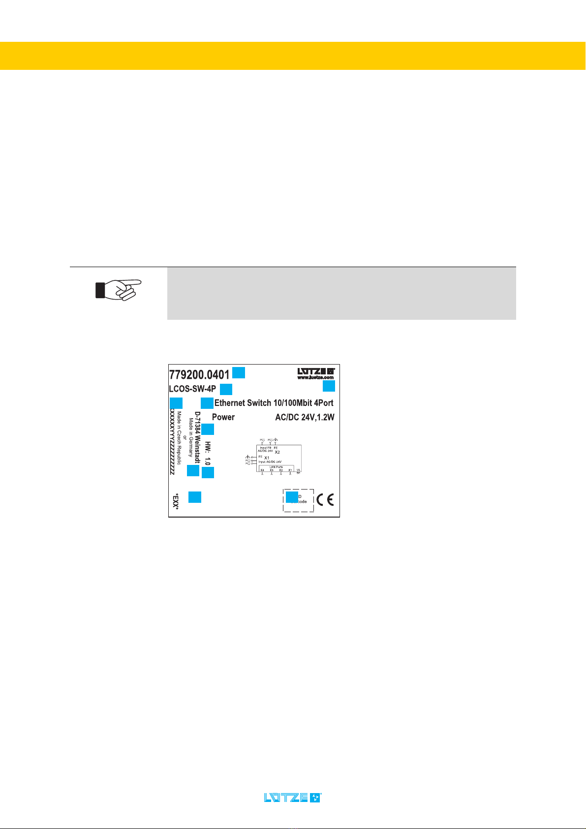
8.1 Identification............................................................................................................................... 33
9 Installation / Uninstallation Hardware........................................................... 42
9.1 Mounting / dismounting of components ..................................................................................... 42
9.2 The control unit LCOS-AB-I controlled via IO-Link .................................................................... 53
9.3 Wiring......................................................................................................................................... 54
9.4 Pin assignment .......................................................................................................................... 54
10 Commissioning Hardware ............................................................................. 55
10.1 Safety instructions .............................................................................................................. 55
10.2 Commissioning the control unit LCOS-AB-I............................................................................... 56
11 Software Installation....................................................................................... 59
11.1 System requirements................................................................................................................. 59
11.2 Download................................................................................................................................... 59
11.3 Installation of PACTware and HART DTM driver ...................................................................... 59
11.4 Installation of the Lütze DTM driver .......................................................................................... 67
11.5 Installation USB Driver ............................................................................................................. 71
12 Commissioning Software............................................................................... 73

AirBLOWER ▪ Content
2
TRANSPORTATION
12.1 Parameters set via HART interface .......................................................................................... 73
12.2 Device catalog ........................................................................................................................... 73
12.3 Parameters set via IO-Link interface ......................................................................................... 83
12.4 Parameters via Siemens PCT (Port Configuration Tool) ........................................................... 84
13 Operation......................................................................................................... 95
13.1 Commissioning the AirBLOWER ............................................................................................... 95
14 Maintenance Hardware................................................................................... 96
14.1 Installation, maintenance or conversion work on the system ............................................ 96
14.2 Maintenance of the components............................................................................................ 96
15 Maintenance Software.................................................................................... 97
16 Final Shutdown and Disposal........................................................................ 98
17 Error help......................................................................................................... 99
17.1 Detailed error help ................................................................................................................... 100
18 Service........................................................................................................... 101
19 Appendix ....................................................................................................... 102
19.1 Overview of the other applicable documents attached ............................................................ 102
20 Appendix A.................................................................................................... 103
20.1 Table device data (Parameter settings) .................................................................................. 103
21 Appendix B.................................................................................................... 104
21.1 Table process data ................................................................................................................. 104
22 Appendix C.................................................................................................... 105
22.1 Events Table ........................................................................................................................... 105
23 Appendix D.................................................................................................... 106
23.1 Online help configuration ........................................................................................................ 106
23.2 General values......................................................................................................................... 106
23.3 Temperature sensors (inputs).................................................................................................. 107
23.4 Alarm (Relay)........................................................................................................................... 108
23.5 Air conditioning unit (Relay)..................................................................................................... 109
23.6 Fault reports............................................................................................................................. 110
23.7 Fan output................................................................................................................................ 111
24 Appendix E.................................................................................................... 112
24.1 Terms and abbreviations ......................................................................................................... 112
25 Revision history............................................................................................ 115

AirBLOWER ▪ Instruction Content
3
TRANSPORTATION
1 Instruction Content
These operating instructions are part of the AirBLOWER fan bench, the PT100
Sensors, AirBLOWER control unit and the entire AirBLOWER. The operating
instructions contain important information on the safety and operation of the unit.
Please read the operating instructions before using the unit to avoid possible
dangers and to ensure proper use.
These instructions must be read and understood before installing,
operating, maintaining or dismantling the device.
Keep the document at hand at all times.
This is valid until the disposal of the device or its modules. Please pass on the
operating instructions when renting or selling the device or its modules.
Risk of injury and damage to equipment caused by non-observance of the
operating instructions.
The instructions contain important information on safety, commissioning,
operation, maintenance and disposal of the corresponding device.
Before installation or use, carefully read these instructions in order to rule out
possible dangers and damage and to guarantee correct use
These operating instructions describe the AirBLOWER control unit and
various configuration elements in this context in the following configuration
state:
1. Firmware Version 1.42
2. AirBLOWER IODD V4.0
3. PACTware V4.1 SP4
4. Lütze HART DTM V1.00.1703
5. Siemens TIA Portal V15 Upd3
6. Siemens S7 PCT V3.5 + Upd1
7. IQ² PDCT V1.5.0
These operating instructions can also be found on the website of
Friedrich Lütze GmbH - www.luetze.com
For example, search for the part number "777000.1011" or use the following
link. (You can click on it.) Scroll down to get to the download area.
LINK to AirBLOWER fan bench

AirBLOWER ▪ General Information
4
TRANSPORTATION
2 General Information
2.1 Safety instructions and technical information
This document contains several safety messages. Each safety message contains
a defined signal word and a color. The color and the word are referring to an alert
level. There are 4 levels. The safety messages point out hazardous situations and
give information on how to avoid these.
Additionally following symbols can be found. These refer to important technical
information and instructions:
2.2 Copyright
This document is intended for the operator and his employees. It is forbidden to
give the content to a third party, to duplicate, exploit or impart it. The Friedrich
Lütze GmbH has to allow it explicit in writing.
General data, text, images and drawings are copyrighted and are liable to the
industrial property right. Contravention can be prosecuted. The named brands
and product names in this document are trademarks or registered trademarks by
titleholder.
2.3 Disclaim of Liability
The document was written under consideration of the applied standards,
regulations and the current state of technology.
The content is verified of accuracy. Discrepancies are not excluded. For those
discrepancies we disclaim liability. Applicable changes and additional information
will be in the next version of the document.
Indicates a hazardous situation, which if not avoided will result in death
or serious injury.
Indicates a hazardous situation, which if not avoided can result in death
or serious injury.
Indicates a hazardous situation, which if not avoided can result in minor
or moderate injury.
Indicates a situation which could damage the product or the environment.
This notice does not apply to personal injury.
Refers to important technical information.
This indicates to the user a specific action that must be performed to
operate the device safely.
Refers to the use of different tools.

AirBLOWER ▪ General Information
5
TRANSPORTATION
The Friedrich Lütze GmbH does not assume liability for any damages and
accidents of following reasons:
▪ Nonobservance of the document
▪ Untrained and unqualified personnel
▪ Non conventional use
▪ Non approved reconstructions and functional modifications of the product
▪ Using non original or non admitted parts or equipment
2.4 Standards and norms
The AirBLOWER is state of the technology and comply with the applicable safety
regulations and the corresponding harmonized European standards (EN).
(As at: 2018-10-10)
EN 61131-2 Industrial-process control systems - Instruments with
analogue inputs and two- or multi-state outputs - Part 2:
Guidance for inspection and routine testing (IEC 65B/957/
CD:2014)
EN 61000-6-2 Electromagnetic compatibility (EMC) - Part 6-2: Generic
standards - Immunity standard for industrial environments
(IEC 77/488/CDV:2015); German version FprEN 61000-6-
2:2015
EN 61000-6-4 Electromagnetic compatibility (EMC) - Part 6-4: Generic
standards - Emission standard for industrial environments
(IEC 61000-6-4:2006 + A1:2010); German version
EN 61000-6-4:2007 + A1:2011
UL 61010-1 Safety requirements for electrical equipment for
measurement, control and laboratory use - Part 1: General
requirements (IEC 61010-1:2010 + Cor. :2011); German
version EN 61010-1:2010
UL 61010-2-201 Safety Requirements for Electrical Equipment for
Measurement, Control, and Laboratory Use - Part 2-201:
Particular Requirements for Control Equipment (IEC 65/
582/CD:2014)
The current issue status of the standards as well as further information
on the product can be found in the respective data sheets.
The constantly updated data sheets can be found at www.luetze.com
Here you will always find the latest documents (e.g. operating instructions) for
the products as well as further articles and technical information.

AirBLOWER ▪ General Information
6
TRANSPORTATION
2.5 Scope of validity of the manual
These operating instructions apply exclusively to devices with the following part
number(s):
1.) 777000.1011 - AirBLOWER fan bench (hooked-in variant)
2.) 777100.0011 - Control unit for AirBLOWER LCOS-AB-I with push-in terminals
3.) 773900.0001 - PT100 - Temperature sensor for control unit (Set of 3)
The 10-digit part number of the device can be taken from the first number on the
Identification label.
2.5.1 Identification label
The identification plate contains the required markings for the respective product
and provides important technical data.
The identification plate, which has the following structure, is located on the
device:
:
Abb. 1: Identification plate (example)
The identification label contains the following information:
1. Part number
2. Assembly designation / module description
3. Module Description
4. Version number / Firmware Version (SW) (Empty in the example)
5. Hardware Revision (HW)
6. Serial number (X) / place of manufacture (YYY) / batch identification (Z)
7. Company address / place of production (YYY: "LUT" for Weinstadt and "EQQ"
for Czech Republic)
8. Block diagram
9. Company name / web address
10.Approvals / declarations of conformity (e.g. CE marking, UL, etc.)
11.2D barcode with product information
Note the identification label.
▪ The identification label should always be visual
▪ If there is a fault, the part number and serial number are needed.

AirBLOWER ▪ General Information
7
TRANSPORTATION
2.6 Approvals
2.6.1 Notes on CE labelling
Pay attention to the original information signs, inscriptions, type plates
and stickers. Keep them in a readable condition.
The devices comply with the provisions of the following European Directive: 89/
336/EEC Council Directive on the approximation of the laws of the Member
States relating to electromagnetic compatibility (amended by Directives 91/263/
EEC, 92/31/EEC and 93/68/EEC).
The EU Declaration of Conformity is kept available for the competent authorities
in accordance with the above-mentioned EU directives:
Friedrich Lütze GmbH
Bruckwiesenstraße 17-19
71384 Weinstadt
GERMANY / DEUTSCHLAND
Telefon: +49 7151 60530
Telefax: +49 7151 6053277
E-Mail: info(at)luetze.de
The products can be used in industry.
- Immunity to interference: EN 61131-2:2007 Zone B
- Emitted interference:
EN 61131:2007 und CFR-47 Part 15, Subpart B, class B
Strict compliance with the assembly guidelines specified in this
description and operating instructions is a prerequisite for compliance
with the EMC limit values.

AirBLOWER ▪ General Information
8
TRANSPORTATION
2.6.2 FCC Warning Statements
2.7 Applicable documents
Please also read the technical information (e.g. data sheets) of the other
components of the AirBLOWER.
1. The control unit device complies with part 15 of the FCC Rules. Operation
is subject to the following two conditions:
(1) This device may not cause harmful interference, and (2) this device must
accept any interference received, including interference that may cause un-
desired operation. Any Changes or modifications not expressly approved by
the party responsible for compliance could void the user's authority to ope-
rate the equipment.
2. Any Changes or modifications not expressly approved by the party respon-
sible for compliance could void the user's authority to operate the equip-
ment.
This equipment has been tested and found to comply with the limits for a
Class B digital device, pursuant to part 15 of the FCC Rules. These limits
are designed to provide reasonable protection against harmful
interference in a residential installation. This equipment generates, uses
and can radiate radio frequency energy and, if not installed and used in
accordance with the instructions, may cause harmful interference to
radio communications. However, there is no guarantee that interference
will not occur in a particular installation. If this equipment does cause
harmful interference to radio or television reception, which can be
determined by turning the equipment off and on, the user is encouraged
to try to correct the interference by one or more of the following
measures:
▪ -Reorient or relocate the receiving antenna.
▪ -Increase the separation between the equipment and receiver.
▪ -Connect the equipment into an outlet on a circuit different from that
to which the receiver is connected.
▪ -Consult the dealer or an experienced radio/TV technician for help.
Further documents are valid in conjunction with these operating
instructions. We accept no liability for damage caused by non-
observance of these instructions.
This technical information and documents can also be found on the
website of Friedrich Lütze GmbH - www.luetze.de
There you enter the article numbers of the respective articles into the search.

AirBLOWER ▪ General Information
9
TRANSPORTATION
2.7.1 The AirBLOWER
The AirBLOWER mainly consists of three assemblies:
2.7.1.1 AirBLOWER fan bench (hooked-in variant)
Part no. 777000.1011 - AirBLOWER consisting of 3 DC 24 V axial fans for
mounting on AirSTREAM. For the dissolution of air layers with the aid of the
control unit LCOS-AB-I.
2.7.1.2 AirBLOWER control unit LCOS-AB-I
Part no. 777100.0011 - LCOS-AB-I with push-In terminals
- The LCOS-AB-I control unit is used to control and monitor the AirBLOWER fan
bank (777000.1011).
2.7.1.3 PT100-Temperature sensor for control unit LCOS-AB-I
Part no. 773900.0001 - Three temperature sensors for controlling the
AirBLOWER LCOS-AB-I control unit.
2.7.1.4 Further accessories for mounting:
USB cable for configuration, AirBLOWER modules, AirBLADEs, adapters,
adaptation brackets, module attachments, etc.
2.7.2 Observe other applicable documents
When operating the AirBLOWER, also observe all other operating instructions,
included in the other components of your system.
For reasons of clarity, we would like to point out that these operating instructions
cannot describe all conceivable problems in connection with the use of this
device.
Should you require further information or encounter special problems that are not
dealt with in sufficient detail in the operating instructions, you can request the
necessary information about service from Lütze. (See chapter „18 Service“ on
page 101
For a better understanding of the AirBLOWER or the AirSTREAM system,
please also read chapter „7 System description“ on page 28.
Always keep these operating instructions and the other applicable
documents (e.g. data sheets, package inserts, declarations of conformity,
etc.) at hand so that they are available when required.
This applies until the device is disposed of. Hand over all documents in case of
sale, distribution or rental of the device.

AirBLOWER ▪ General Information
10
TRANSPORTATION
2.8 Applicable documents - Software
2.8.1 PACTware® 4.1
PACTware is a manufacturer- and fieldbus-independent software for adjustment
of field instruments.
PACTware is freeware, but you should still visit the homepage:
www.pactware.com. There you will find current documentations and contact
persons.
2.8.2 HART CommDTM (FDT1.2)
The HART CommDTM is an interface between FDT 1.2 compliant FDT frame
applications (e.g. PACTware) and HART device DTMs. It enables data exchange
between the device DTM and the physical device via a HART modem connected
to the serial or USB interface of the PC.
HART CommDTM is freeware, but you should still visit the homepage:
www.codewrights.de. There you will find current documentations and contact
persons.
2.8.3 LÜTZE DTM driver
The Device Type Manager (DTM) represent the specific device driver and contain
all configurable properties. This makes it possible to display measured values,
support operation with graphics or perform a diagnostic function. It is also
possible to carry out offline or online parameters.
2.8.4 LÜTZE LCON ZB USB driver
For installing the LÜTZE LCON ZB USB data cable for parameter setting.
This manual contains all the steps required for installation. However, if
you have any questions, please contact Service.
This manual contains all the steps required for installation. However, if
you have any questions, please contact Service.
If you are using a comparable product or driver, please also read the
relevant technical documentation.

AirBLOWER ▪ Safety
11
TRANSPORTATION
3Safety
3.1 Contents of the operating instructions
These operating instructions must be read and observed before any work is
carried out on or with the units. This applies to all persons who come into contact
with the devices. Trained personnel and specialists, especially electricians (also
see“Electrically qualified persons”onpage 13.) who have already worked with
similar equipment should also have read and understood the manual.
3.2 Applicable documents
3.3 Appropriate Use
The products are only to be operated for the cases specified here in the operating
instructions. The AirBLOWER is designed for industrial use in factory, machine
and building automation. The AirBLOWER is operated exclusively in a control
cabinet. The AirSTREAM system from LÜTZE is recommended.
Due to the modular design, the devices in the LCOS system can be supplied
either via existing connectors or via the power bus (PB). Due to the possibility to
supply the devices with AC, they can also be used in building automation.
These instructions must be read and understood before installing,
operating or maintaining the devices.
Risk of injury and damage to property due to non-observance of the
applicable documents*, in particular the safety instructions in the
respective package inserts.
This operating instruction alone is not sufficient if the modules are operated in
one system.
To avoid injury and damage, read the applicable and associated documents
before you plan the system.
*A list of applicable documents can be found in the “Appendix” on page 102.
The products may only be used for the applications specified here in this
operating instruction, in the catalogue and in the associated technical
documentation.
Use of the device in a manner not specified by the manufacturer may impair the
protection and safety provided by the device.
The devices are used exclusively for the purpose contractually agreed
between manufacturer and user.
Any other use or use beyond this is considered improper use. The
manufacturer is not liable for any damage resulting from this.

AirBLOWER ▪ Safety
12
TRANSPORTATION
Also note the following:
The intended use also includes the procedure according to the operating
instructions.
Any other or extended use is considered improper and therefore improper. In this
case, safety and its protection can be impaired. The company Friedrich Lütze
GmbH is not liable for any damages arising from this.
Intended use also includes:
▪ Observing all notes in the operating instructions
▪ Observing all safety instructions
3.4 Product life
The product life cycle of the AirBLOWER is determined on the basis of the
EN/IEC 61709 is calculated and defined. Further details are available on request
from the service department.
Correct and safe operation of the products requires proper transport,
storage, installation and assembly as well as careful operation and
maintenance.
The permissible ambient conditions must be observed. These data are given in
the data sheets.
Operate the devices only in accordance with this intended case and only
in conjunction with the third-party devices and components
recommended or approved by us.
The devices may only be connected to the supply voltage printed on the
identification plate.
To reduce or avoid risks, please ask in case of doubt whether the third-
party devices and components used are approved or recommended by
us.

AirBLOWER ▪ Safety
13
TRANSPORTATION
3.5 Addressees
This operating instruction is directed towards planers, project managers and
programmers, as well as to staff authorized to commission, operate and maintain
the devices and systems. A distinction is made between various qualification
levels of the staff.
3.5.1 Operating Personnel
The operating instructions are directed at the operator and the personnel with the
following areas of competence:
3.5.1.1 Trained Employee
The employees do not have any specialist knowledge. The operator (or an
authorised specialist) has informed the employees about the work to be carried
out and the resulting dangers in the event of improper behaviour and has
instructed them if necessary. The employees have also been informed about the
necessary protective equipment and measures.
3.5.1.2 Experts
The personnel has technical training, knowledge and/or experience in the
respective field and is therefore able to carry out certain work on and with the
device. They are also familiar with the relevant standards, which enable them to
assess the work performed and recognize possible hazards.
3.5.1.3 Electrically qualified persons
The employee has a technical education in the required field. The employee is
capable to perform special operations on and with the product.
The different sections of the document refer to the qualification level of the
operating personnel.
According to European Standard EN 50110-1:2008-09-01 Section 3.2.3
Working range Competency
Installation, transport and storage Experts
Commissioning, decommissioning Trained Employee
Operation Trained Employee
Servicing and maintenance Experts
Troubleshooting Experts
Risk of injury by usage through insufficient qualified operating
personnel! Misusage through performed insufficient or qualified personnel can
cause property damage and personal injuries.
▪ Tasks which apply special procedures should be done by trained and
qualified employees or experts, especially electricians.
(according to EN 60204-1)

AirBLOWER ▪ Safety
14
TRANSPORTATION
3.6 Responsibility of the operator
Since the device is used in a commercial area, the operator of the device is
subject to the legal obligations for occupational safety:
▪ The operator of the device is obliged to instruct the operating personnel and
to inform himself about the industrial safety regulations.
▪ The operator must ensure that safety, accident prevention and environmental
protection regulations are observed.
▪ The operator must make an appropriate risk assessment on the
▪ Workplace/location to detect and warn of special hazards.
▪ The manual must be kept in the immediate vicinity of the device.
▪ The information in the operating instructions must be followed.
▪ The device may only be operated in technically perfect condition.
3.7 Protective clothing
The individual sections refer to the qualification level of the personnel.
Wear appropriate ESD protective clothing.
Static charging can damage individual components and lead to a defect in the
device.
Always follow the employer's instructions and regulations.

AirBLOWER ▪ Safety
15
TRANSPORTATION
3.8 Changes and modifications to the devices
Do not make any changes or modifications to the devices that have not been
expressly and in writing previously approved by Friedrich Lütze GmbH.
3.9 Safety device
3.10 Special safety notes
The AirBLOWER and its components are state of the art and comply with the
applicable safety regulations and the corresponding harmonized European
standards (EN) - see “Standards and norms” on page 5.
The following applies to the users:
▪ relevant and national accident prevention regulations
▪ EC directives or other country-specific regulations
▪ generally accepted safety rules
▪ general ESD regulations.
Modifications and conversions lead to personal injury and property
damage!
Unauthorized modifications to the product may result in electric shock or injury
and destroy the product.
▪ Do not make any changes or modifications to the product.
▪ If a modification or change cannot be avoided, have the modification
approved in writing by Friedrich Lütze GmbH.
Danger to life due to errors in the overall system!
Sabotage of the devices can lead to serious errors in the overall system.
Install the AirBLOWER fan bench, the AirBLOWER control unit LCOS AB-I and
the PT100 temperature sensors of the control unit in such a way that they are
not freely accessible to unauthorised personnel and other persons.
Electric shocks and material damage due to overvoltage on the module.
Overvoltage on the module may result in electric shock if touched. The modules
can be destroyed by the high voltage.
Electric shocks and material damage caused by bypassing or bridging
protective and safety equipment.
Do not bypass or bridge the protective and safety devices. Overvoltage can
result in electric shock and damage to the equipment.

AirBLOWER ▪ Safety
16
TRANSPORTATION
Short-circuits and electric shocks due to incorrect application of the
voltage!
Current can injure persons and destroy the devices. Before commissioning,
disconnect the entire system from the power supply and check the connections
after applying power.
Accidents during installation or maintenance due to electrical voltages!
When carrying out installation or maintenance work, disconnect the modules
from the power supply (pull out the mains plug). This prevents accidents
caused by electrical voltages.
Electric shocks and material damage due to excessive voltages.
Non-compliance with the specified voltage limits can result in electric shocks and
the modules can be destroyed.
Only use the approved components in the system.
Risk of injury from electric current.
Current can injure persons and destroy the device. For this reason, disconnect
the system from the power supply before installation.
Risk of injury and material damage through non-observance of the
operating instructions.
Always read the operating instructions before planning the system in order to
avoid or reduce risks and damage. (The instruction leaflet does not replace the
operating instructions of the product.
You can also find these operating instructions at www.luetze.com.
For electrical welding work on frames, all assemblies and their
connections must be disconnected.
If electronic assemblies are mounted on the frame, then all connections to and
from these assemblies must be disconnected beforehand.
Non-observance can destroy the devices by equalising currents.

AirBLOWER ▪ Safety
17
TRANSPORTATION
3.11 Further safety notes
Follow the ESD regulations.
Only use certified components. Only this way a reliable functioning is
ensured.
Follow the valid safety regulations and general regulations regarding the
technical standards.
The conductor size has to be selected dependig on the load current and
must be conform with international and national ruls and standards.
ATTENTION!
The supply cable of the AirBLOWER control unit LCOS-AB-I must be
suitable for an operating temperature range of -25 °C to +70 °C.
The connecting cables must be designed for the ambient temperature.
To ensure UL certification of the AirBLOWER control unit LCOS-AB-I,
only use the push-in terminals or plug-in terminals supplied or
recommended by us.
For UL applications (e.g. the AirBLOWER control unit LCOS-AB-I):
An UL-approved 3A fuse must be connected upstream of the device.
For UL applications (e.g. the AirBLOWER control unit LCOS-AB-I):
Ambient temperature: +70 °C: The module must be installed in a fire
protection housing suitable for the end application.
The device is intended to be used in indoor applications and be mounted
in cabinets.

AirBLOWER ▪ Product Overview
18
TRANSPORTATION
4Product Overview
4.1 Product description
The AirBLOWER is intended to provide a balanced climate in switch cabinets,
avoid heat nests (so-called hotspots) and protect the components from
overheating.
Three PT100 temperature sensors of the AirBLOWER LCOS-AB-I control unit
continuously measure the temperature in the control cabinet. If the previously set
temperature limits are exceeded or not reached, the AirBLOWER fan bank is
activated and the control cabinet temperature is adjusted accordingly.
A control cabinet equipped with an AirSTREAM frame has improved heat
dissipation. Practical tests provide impressive results: With the AirBLOWER, the
average cabinet temperature can be reduced by up to 10K.
Operation of the LÜTZE AirBLOWER requires significantly less energy than
active control cabinet cooling. In addition, the AirBLOWER does not have to be
used in continuous operation, but can be operated in clocked mode.
The AirBLOWER consists of three modules that are connected to each other. The
individual modules are presented below.
4.2 The AirBLOWER fan bench (hooked-in variant)
Part no. 777000.1011 AirBLOWER fan bench
Description
AirBLOWER fan bench consisting of 3 DC 24 V axial fans for mounting on
AirSTREAM. For the dissolution of air layers with the aid of the control unit
LCOS-AB-I.
Table of contents