Lütze LEOS-FM-ETH-SW-WR-LUE User manual

Operating instructions
LEOS
Full Managed Ethernet Switch
804202, LEOS-FM-ETH-SW-WR-LUE
Version 04
11.06.2019

Lütze Transportation GmbH
Bruckwiesenstrasse 17-19
D-71384 Weinstadt
Tel.: +49 (0) 7151 6053-545
Fax: +49 (0) 7151 6053-6545
Sales.Transportation@luetze.de
www.luetze-transportation.de

LEOS Full Managed Ethernet Switch ▪ Contents
Contents
1 Foreword ....................................................................................................... 5
2 General information ..................................................................................... 6
2.1 Explanation of symbols........................................................................................................... 6
2.2 Copyright ................................................................................................................................ 6
2.3 Disclaimer ............................................................................................................................... 7
2.4 Identification plate................................................................................................................... 7
3 Safety............................................................................................................. 9
3.1 Appropriate Use...................................................................................................................... 9
3.2 Addressees............................................................................................................................. 9
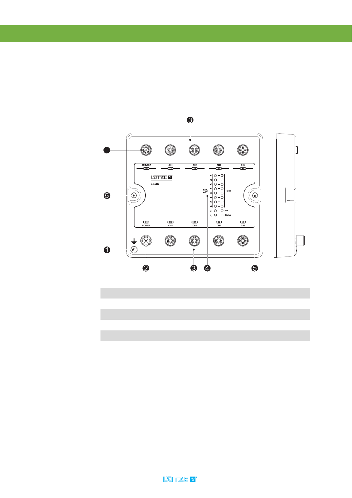
4 Product Overview....................................................................................... 10
4.1 Overview of product features................................................................................................ 11
5 Installation .................................................................................................. 12
5.1 Mounting options .................................................................................................................. 12
5.2 Wall mounting ....................................................................................................................... 12
5.3 Mounting adapter set ............................................................................................................ 13
5.4 Grounding............................................................................................................................. 15
5.5 Wiring.................................................................................................................................... 16
6 Initial commissioning................................................................................. 18
6.1 Factory settings .................................................................................................................... 18
6.2 Initial commissioning............................................................................................................. 18
6.3 Replacing a defective device ................................................................................................ 19
7 Configuration via web interface ................................................................ 20
8 System settings.......................................................................................... 22
8.1 System configuration and services ....................................................................................... 22
8.2 Ethernet ports (interfaces) .................................................................................................... 22
8.3 Time...................................................................................................................................... 24
8.4 SNMP ................................................................................................................................... 25
8.5 SNMP Traps ......................................................................................................................... 26
8.6 DHCP.................................................................................................................................... 27
8.7 LLDP..................................................................................................................................... 29
9 Switch settings ........................................................................................... 30
9.1 VLAN .................................................................................................................................... 30
9.2 QoS ...................................................................................................................................... 32
9.3 Link Aggregation................................................................................................................... 33
9.4 Port Mirroring ........................................................................................................................ 34
10 Diagnostics ................................................................................................. 35
10.1 LED display........................................................................................................................... 35
10.2 Signal contact ....................................................................................................................... 35
10.3 Log files ................................................................................................................................ 36
11 Settings for system access ....................................................................... 38
11.1 IP addresses......................................................................................................................... 38
11.2 User rights ............................................................................................................................ 38
11.3 Configuration files ................................................................................................................. 39
12 USB functions............................................................................................. 40
12.1 Downloading the configuration ............................................................................................. 40
12.2 Uploading the configuration .................................................................................................. 40
12.3 Resetting the configuration ................................................................................................... 40

LEOS Full Managed Ethernet Switch ▪ Contents
12.4 Downloading a diagnostics image ........................................................................................ 41
12.5 Firmware Update .................................................................................................................. 41
13 Firmware Update ........................................................................................ 42
13.1 Firmware update via web interface....................................................................................... 42
14 Diagnostics image...................................................................................... 43
14.1 Call via the web interface...................................................................................................... 43
15 Service......................................................................................................... 44
15.1 Known issues........................................................................................................................ 44
16 Decommissioning and disposal................................................................ 45
17 Amendment index ...................................................................................... 46

LEOS Full Managed Ethernet Switch ▪ Foreword
5
1 Foreword
These instructions are a component of the product:
LEOS Full Managed Ethernet Switch
These instructions must be read and understood before installing,
operating, maintaining or dismantling the device.
Risk of injury and damage to equipment caused by non-observance of the
operating instructions.
The instructions contain important information on safety, commissioning,
operation, maintenance and disposal of the corresponding device.
Before installation or use, carefully read these instructions in order to rule out
possible dangers and damage and to guarantee correct use
Always keep the document to hand.
This applies until the disposal of the product. When selling or lending, pass on
the instructions.
These operating instructions can also be found on the website of
Lütze Transportation GmbH - www.luetze-transportation.com
Search for either the article number "804202", or the product name
„LEOS Full Managed Ethernet Switch“.

LEOS Full Managed Ethernet Switch ▪ General information
6
2 General information
2.1 Explanation of symbols
The manual contains safety information, which is characterized by a signal word
in combination with a certain colour to indicate the warning level. The information
highlights possible dangers and gives instructions on how to avoid them.
You will also find icons that indicate important information and action steps:
2.2 Copyright
This installation manual is intended for the operator and its staff only. It is
forbidden to give the contents to a third party, to duplicate, exploit or otherwise
disclose it unless authorized expressly and in writing by Lütze Transportation
GmbH. Details, texts, images and drawings in the contents are copyright
protected and are subject to commercial property rights. Contravention can be
prosecuting criminally. The trademarks and product names mentioned in this
document are subject to absolute provisions of the effective label right and
property rights of the respective registered owners.
Indicates a dangerous situation which leads to death or serious injuries
if not observed.
Indicates a dangerous situation which can lead to death or serious
injuries if not observed.
Indicates a dangerous situation which can lead to slight or moderate
injuries if not observed.
Indicates a situation which could damage the product or the environment.
This information foresees injuries.
Indicates technically important information to operate the device safely.
Indicates the use of tools.

LEOS Full Managed Ethernet Switch ▪ General information
7
2.3 Disclaimer
The installation instructions have been prepared taking into account the
applicable standards, provisions and in accordance with the state of technology.
The accuracy of the contents of the documentation has been checked, however
deviations cannot be ruled out. No liability is assumed for these deviations.
Amendments and addenda are also made in the next version of the manual.
Lütze Transportation GmbH does not assume liability for damage or accidents
that occur as a result of the following:
• Non-compliance with the manual
• When employing untrained or unqualified staff
• Unintended use
• If there are unauthorized changes or functional changes to the device
• If non-original or licensed parts or equipment are used
2.4 Identification plate
The identification plate, which has the following structure, is located on the switch:
Fig. 1: Example of an identification plate
The identification plate contains the following information:
• Part Number
• Hardware revision
• Module description
• MAC-ID if available, further MAC-IDs see Chapter 11.1 “IP addresses” on
page 38
• Production date
• Software version
• Serial number:
• Data Matrix Code, contents: serial number, part number, date, MAC-ID
• QR Code, reference to product information
Note the identification plate.
• The identification plate should always be legible
• If there is a fault, the part number and serial number are needed.
D-71384 Weinstadt
Made in Germnay
www.luetze.com
803101.01
Rev. A
16DI DC 24 V-36V
LION-DI16-24V-36V-LUE
0000000001
1.00 LSGP
S/N:
C/N:
SW:
Date: 31.12.12
299999
C

LEOS Full Managed Ethernet Switch ▪ General information
8
2.4.1 QR Code – Product information
The code refers to additional product information in the online catalog on the
Lütze Transportation website. To reach this site, proceed as follows:
1. Scan the QR code with a smartphone or other device that can read QR codes.
2. The default browser opens with the corresponding page.
Fig. 2: Screenshot Online Catalogue – Language selection
3. Select a corresponding language.
4. The device is displayed in the Online Catalogue. Under Downloads you can
download additional technical documentation.

LEOS Full Managed Ethernet Switch ▪ Safety
9
3 Safety
3.1 Appropriate Use
A correct and safe operation of the device requires an appropriate transport,
proper storage, mounting, installation commissioning, operation and
maintenance. The permissible ambient conditions must be observed. Information
in the accompanying documentation must be observed.
3.2 Addressees
The operating manual is directed towards planners, project managers and
programmers, as well as to staff authorized to commission, operate and maintain
the devices and systems. A distinction is made between various qualification
levels of the staff.
3.2.1 Operating staff
Trained staff
The staff have been trained by the operator in the assigned tasks and have been
informed of the possible resulting dangers. They do not have any technical
expertise.
Experts
The staff have a technical education, expertise and/or experience in the relevant
area and thus are able to perform specific tasks on and with the device.
Electricians
The staff have a technical education in the relevant area and thus are able to
perform specific tasks on and with the device.
The qualification levels of the staff are referred to in the individual sections.
Risk of injury by use through insufficiently qualified operating staff!
Incorrect handling by unqualified or insufficiently qualified staff can lead to
injuries and damage. Activities, which require specific actions, should only be
performed by staff trained in advance, or by experts, notably electricians.

LEOS Full Managed Ethernet Switch ▪ Product Overview
10
4 Product Overview
The LEOS Full Managed Ethernet Switch has been developed for use in industry
and in transport applications. The switch can be configured via an integrated web
interface.
The device is characterized by its robust design, port, prioritization, port disabling,
signal contact, configuration management, and remote diagnostics.
1PE connection
2 Auxiliary power supply with relay
3Ports
4LED display
5Holes for wall mounting
6 Service interface (digital input & USB)
6

LEOS Full Managed Ethernet Switch ▪ Product Overview
11
4.1 Overview of product features
Feature Description
Housing IP54, Wall mounting
Supply Range 24 – 110 V
Hardware Store and Forward Switching Mode
Autonegotiation
Autocrossing
Autopolarity
Signal contact AC/DC 150 V
LEDs: Logic supply, Link & Activity, Speed,
Digital input, relay output
8 Port witj 10/100BASE-TX
Software RSTP
LLDP
SNMP (SNMP Traps)
NTP
DHCP (DHCP Option 82, Static Leases)
QoS
Tag-based VLAN
Port Mirroring
Port Monitoring
Webinterface
Firmware Update
Event Logging
Configuration Save
Cable Test
158
36,4
144
140
LEOS
X1
X2
X3
X4
X5
X6
X7
X8
DI
ULStatus
RO
X9
X10
X5
X1
X6
X2
X7
X3
X8
X4
POWER
SERVICE
CH5
CH1
CH6
CH2
CH7
CH3
CH8
CH4
LNK/
ACT SPD

LEOS Full Managed Ethernet Switch ▪ Installation
12
5 Installation
5.1 Mounting options
5.2 Wall mounting
Never wire electrical connections when they are connected to the power supply!
Never wire live wires!
Do not carry out any assembly work on the device when it is connected to the
power supply.
1ISO 4762 M5×25 hexagon socket screw
(equal: DIN 912 M5x25)
2ISO 7089 M5 washer (equal: DIN 125 A M5 washer)
3DIN 6797 A M5 lock washer (No ISO Standard available.)
123
The specified screws and washers are not included with the delivery.

LEOS Full Managed Ethernet Switch ▪ Installation
13
5.3 Mounting adapter set
The switch can only be mounted on the DIN rail using the adapter set 804210.
The adapter set is not included with the delivery.
For mounting you need a T20 screwdriver (also called a TX20 or 6-lobe
screwdriver (T20)).
1DIN rail adapter
2 M6x12 flat head screw TX20 (T20)
3LEOS Switch
2
12
3
Torque: 8 Nm

LEOS Full Managed Ethernet Switch ▪ Installation
14
5.3.1 DIN rail mounting
5.3.2 DIN rail end mounting
3
2
1
2
3
1

LEOS Full Managed Ethernet Switch ▪ Installation
15
5.4 Grounding
For mounting you need a hexagonal key, wrench size 3 mm.
Electric shocks and injuries through incorrect grounding.
• The devices must be grounded by an electrician.
• The ground connection must not be more than 20 cm long. 10 cm is
recommended.
• The ground cable must have a gauge of at least 2.5 mm².
• The cable shoe used must be as wide as possible.
• Always ground the device via the PE connection, but the DIN rail.
• Ground the DIN rail separately in order to comply with the EMC Directive.
Torque: 2 Nm

LEOS Full Managed Ethernet Switch ▪ Installation
16
5.5 Wiring
5.5.1 X1-X8, channels 1 – 8
All ports of the Ethernet Switch are 4-pin, D-coded M12 jacks. The pin assignment
is prescribed as follows:
5.5.2 X9, power supply
M12 jack 4-pin, A-coded
5.5.3 X10, Service interface
M12 jack 8-pin, A-coded
Pin Signal
1TX+
2RX+
3TX-
4RX-
*The relay can be configured via the web server as a N/O contact or break
contact.
Pin Signal
1 DC 24 - 110 V
2Relay contact*
3DC 0 V
4Relay contact*
Pin Signal
1DI-
2USB 5 V
3USB+
4USB-
5USB 0 V
6NC
7DI+
8NC

LEOS Full Managed Ethernet Switch ▪ Installation
17
5.5.4 Connecting lead
5.5.5 Important notice for reaching protection class IP54
In order to reach protection class IP54 when assembled, the recommended
torques must be observed during assembly.
Only use connecting leads that fulfil the following criteria:
• Electronic equipment on rolling stock EN 50155
• Shock and vibration EN 61373
• Railway applications - Rolling stock - Electrical connectors, requirements and
test methods EN 50467
• Fire protection in rail vehicles EN 45545-1
• Ambient temperature: -40°C – +85°C
• Protection class (fitted) IP54
This is the only way to guarantee the correct operation of the Ethernet
Switch.
Recommended torques for protection class IP54
M12 connections 0.6 Nm
M12 screw plug 0.4 Nm
All unused connections must be closed with the recommended torque using the
screw plugs supplied.

LEOS Full Managed Ethernet Switch ▪ Initial commissioning
18
6 Initial commissioning
6.1 Factory settings
The device is supplied pre-configured. The factory-settings configuration has
been selected so that the device the at all Ethernet ports can be identified
immediately after the device is switched on. The following are the factory settings:
6.2 Initial commissioning
Proceed as follows for the initial commissioning:
1. Connect the power supply.
2. Connect the PC / laptop to one of the Ethernet ports 1-8 on the device.
3. The connected PC / laptop must have the following network settings: Automat-
ically detect IP address.
4. Open a web browser and enter the device's LAN-IP address.
5. Carry out the desired configuration of the device.
6. Connect the switch to your network devices.
Web interface IP address: 192.168.1.1 (LAN)
Web interface username admin
Web interface password: password
Web interface access: Port 1-8
Ethernet ports: enabled
Auto-negotiation enabled
DHCP
•Pool
• Sub-network mask
• Gateway
enabled
192.168.1.10-254
255.255.255.0
192.168.1.1
VLAN, QoS, Port mirroring: disabled
Link aggregation: disabled
NTP disabled
SNMP enabled
Signal contact: Normally open
Signal contact events: Power; over and
under-temperature
RSTP enabled
Broadcast storm protection disabled

LEOS Full Managed Ethernet Switch ▪ Initial commissioning
19
6.3 Replacing a defective device
After commissioning the device, the configuration can be downloaded via the web
interface or by USB. The steps necessary for this are explained in chapters:
Chapter 7 “Configuration via web interface” on page 20
and
Chapter 12.1 “Downloading the configuration” on page 40
or
Chapter 12.2 “Uploading the configuration” on page 40.

LEOS Full Managed Ethernet Switch ▪ Configuration via web interface
20
7 Configuration via web interface
Configuration via web browser allows changes to be made to the device settings
via the network. To do this, the IP address of the switch has to be called in a web
browser. For the preset LAN-IP address, see Chapter 6.1 “Factorysettings”on
page 18 When the page is opened in the browser, a warning is issued first. This
is normal because it is not possible to issue a secure certificate for IP address.
To gain access to the system, the user has to verify themselves. This is done with
a username and password. The web interface is then loaded.
The default access is
User: admin
Password: password
It is not possible to have a certficate created for every desired IP address.
• Check the IP address and its certificate.
If a password is lost, it is only possible to reset the device in the factory.
The existing configurations cannot be backed up. There is no master
password.
• Keep the password secure.
This manual suits for next models
1
Table of contents
Popular Network Router manuals by other brands

Sierra Wireless
Sierra Wireless AirLink GX Series quick start guide

Avaya
Avaya 8800 Series Planning and Engineering

Contemporary Controls
Contemporary Controls BASrouter Portable installation guide

Billion
Billion BiPAC 7300N quick start guide

NetComm
NetComm NB1 user guide

LevelOne
LevelOne WBR-3406TX Quick installation guide

Patton electronics
Patton electronics 3210 Specification sheet

Nokia
Nokia 7705 SAR-W Series Guide

D-Link
D-Link DIR-879 user manual

Simons Voss Technologies
Simons Voss Technologies WaveNet Radio Network 3065 user manual

Parvus
Parvus DuraMAR 5915-2X user manual

TP-Link
TP-Link SafeStream TL-ER5120 user guide