Lakeland Mills CF1128 User manual

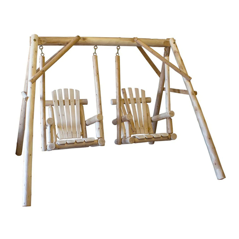
CF1128/CFU28 CEDAR LOG YARD SWING
Please check contents before assembly. If any items are missing or damaged, do not take the unit back to the
store. Call 1-800-427-5136 for customer service and we will save you time by correcting any problems directly
for you.
Read all instructions before starting.
To start hex washer head screws, hammer into
wood about 1/2” then use wrench or socket to
tighten.
Do not completely tighten any screws until the
unit is fully assembled and setting on a level
surface.
Use a rubber mallet (or a block of wood be-
tween the hammer and the unit) to drive dow-
eled ends into holes as far as possible.
YARD SWING COMPONENTS
NOTE: Cracks or Checks in logs are part of the natural
beauty of cedar logs and should not be considered defects.
TOOLS REQUIRED
NOTE:
YARD SWING HARDWARE
(Shown smaller than actual size)
1 - Top Rail
2 - 24” Arms
Preassembled Swing Back
Preassembled Swing Seat
2 - 45”
Swing Bars
2 - Seat
Ends
Ten
Screws
Two 3/8” x 5”
Eye Bolts
Two Barrel
Nuts
Two 3/8”
Nuts
Four
1/4” x 5”
Hex Washer
Head Screw*
Six 3/8”
Washers
Two
3/8” x 8”
Bolts
Twelve
1/4” x 3”
Hex Washer
Head Screws*
Rubber
Mallet
Block of
Wood
& Hammer
Tape Measure
Regular
Screwdriver
or
Pencil
4 - Legs
6 - 34 3/4” Braces
Two 1/2” x 6”
Eye Bolts
Two 1/2”
Nylock Nuts
Four 1/2”
Washers
Two S
Hooks
2 - 12”
Arm Supports
3/4” deep well
socket
9/16” deep well
socket
9/16” wrench
7/16” socket or
wrench
3/8” socket or
#2
Philips
Screwdriver
* Hex Washer
Head Screws may
be substituted
with Lag Screws
and Washers.
Optional
NOTE: Using a battery or electric power drill with a
socket attachment will make assembly easier and
faster.

32”
24”
22 1/2”

SEAT ASSEMBLY
STEP 4 Lay assembled seat on ground. Insert doweled
ends of uprights on assembled back into 1-
1/4” holes on the back seat rail, adjusting up-
rights in or out as needed to align properly.
Do not tap on seat back with hammer.
To keep the seat rail from splitting, lay the
back on the ground and drive the seat on by
hitting on the bottom of the seat assembly.
STEP 5 Insert 12” arm support into hole in the arm,
then into hole in the top of the seat end.
Drive doweled ends in as far as possible.
Fasten arm to the back upright by tightening
the preinstalled 1/4” x 5” hex washer head
screw into the pilot hole in the arm with a
wrench. Repeat on other arm.
STEP 6 Secure all doweled joints in place with screws
perpendicular to the doweled end as shown at
right.
Install seat end onto seat. Align holes in seat end with
dowels on seat as shown in picture right. Repeat on
other side. Secure with screws perpendicular to dowel.
(See circle figure below). IMPORTANT: The single
hole should be placed toward the front of the seat. (See
below).
STEP 4a
Please Note: After you have installed the seat ends onto the
seat secure with (4) 2 1/2” screws. See figure below for how
to put screws in..

Place barrel nut into horizontally drilled hole in end of swing
bar. Position barrel nut with screwdriver and screw in 5” eye-
bolt with 3/8” washer as shown. TIGHTEN DOWN SE-
CURELY! Repeat on other swing bar. Figure 7
Fasten swing bars to side of unit as shown. With hammer, tap a
5” hex washer head screw through the bottom hole in swing bar
and into pilot hole (11” from the back of the seat end) on seat
end. Tap 5” hex washer head screw through the upper hole in
the swing bar and into arm about 1/2” deep at the point 15” from
the back of the arm. (This gives a suggested pitch of the seat.
You may change the pitch by altering the location of the hex
washer head screws in the arm.) Tighten down hex washer
head screws. Figure 8
STEP 7
STEP 8
Pilot holes is 11” from the
rear of the seat end.
Figure 7
Figure 8
If you have hardware left over after completing your unit, it
most likely has been assembled incorrectly, and may not be
safe to use. Please call Customer Service at 800-427-5136 for
assistance.
NOTE
SEAT TO FRAME ASSEMBLY
Install the assembled swing to the frame. It is recom-
mended a minimum of two people for this this step.
STEP 9
STEP 10 Tighten all hex washer head screws firmly. Your unit is
now ready for finishing or immediate use. Relax and en-
joy.
Install on level ground. Install not less than 6’ from any
obstructions such as a fence, garage, house, overhanging
branches, lines, or wires.
Check all nuts and bolts for tightness
before and during each usage season.
NOTE:
Factory: 1 Lakeland Place, Edmore, Michigan 48829, Phone: 800-427-5136 Fax: 989-427-5824
www.lakelandmills.com
Look for assembly videos on:
https://www.youtube.com/watch?v=jg2BRgWMVpg&t=1s
https://www.youtube.com/watch?v=-OmqxSrmkYM
Lakeland Mills recommends:
WeatherSeal Premium Oil-Based Exterior Wood Stain & Sealant
www.ContinentalProd.com
This manual suits for next models
1
Other Lakeland Mills Swing Set manuals
Popular Swing Set manuals by other brands
Little Tikes
Little Tikes 633843M manual

Karibu
Karibu GS 45018 Building instructions

gartenpirat
gartenpirat Single Kiefer KDI Assembly instruction

Plum
Plum Roloway Assembly instructions

LifeSpan Kids
LifeSpan Kids AMBER PE83 owner's manual

Big Backayard
Big Backayard F23242 Installation and operating instructions
Creative Playthings
Creative Playthings Playtime PS10LIN Assembly manual

Hedstrom
Hedstrom NEPTUNE GYM manual

sweeek.
sweeek. GALERNE PS170MBGRE Assembly instructions

Gorilla
Gorilla Laredo 1300 instructions

Backyard Discovery
Backyard Discovery SPRINGBORO 40014 owner's manual

VEVOR
VEVOR QQZJ-95 Series manual