Lanner electronics MB-X71 Series User manual

MB-X71 Series
Socket 478 Network Security
Appliance Control Board
( 2xGBe, 4x10/100 LANs )

COPYRIGHT©
This document is copyrighted by the original manufacture. The original manufacturer
reserves the right to make modifications to the product(s) described in this manual at any
time without notice. This manual may not, in whole or in part, be photocopied,
reproduced, transcribed, translated, or transmitted in whatever form without the written
consent of the manufacturer, except for copies retained by the purchaser for backup
purposes. All rights are reserved.
TRADEMARKS
Pentiumis a registered trademark of Intel Corporation.
The following are trademarks or registered trademarks of their respective companies:
IBM, Intel, AMD, Cyrix, Award, AMI, S3, Microsoft, Windows, Windows NT, Novell, SCO,
PC/104, PICMG, ALI, UMC, SMC, Winbond. Products mentioned in this manual are for
identification purposes only. All names of products or services appearing in this manual
are the trademarks or registered trademarks of their respective organizations and
companies.
Copyright 2001
Ver.No. 1.0
LEI-UM-MB-X71 Series
Date:2003/2/1

TABLE OF CONTENTS
CHAPTER 1 INTRODUCTION 1
1.1 SPECIFICATIONS 2
1.2 PACKING CHECK LIST 3
CHAPTER 2 JUMPER SETTING AND CONNECTORS 4
2.1 BOARD OUTLINE OF MB-X71 4
2.2 INSTALLING AND UPGRADING THE CPU 5
2.3 JUMPER SETTING OVERVIEW 7
2.4 JUMPER LOCATIONS FOR MB-X71 8
2.5 JUMPER SETTINGS SUMMARY FOR MB-X71 9
2.6 JUMPER SETTINGS FOR MB-X71 10
2.7 I/O CONNECTOR LOCATIONS FOR MB-X71 11
2.8 I/O CONNECTOR SUMMARY FOR MB-X71 12
2.9 I/O CONNECTORS DESCRIPTION 13
CHAPTER 3 AWARD BIOS SETUP 23
3.1 RUNNING AWARD BIOS 23
3.2 CMOS SETUP UTILITY 24
3.3 STANDARD CMOS SETUP 26
3.4 BIOS FEATURES SETUP 30
3.5 CHIPSET FEATURES SETUP 33
3.6 INTEGRATED PERIPHERALS 35
3.7 POWER MANAGEMENT SETUP 37
3.8 PNP/PCI CONFIGURATION 39
3.9 PC HEALTH STATUS 43
3.10 LOAD FAIL-SAFE DEFAULTS 44
3.11 SET SUPERVISOR / USER PASSWORD 44
3.12 SAVE & EXIT SETUP 45
3.13 EXIT WITHOUT SAVING 45

TABLE OF CONTENTS
CHAPTER 4 DRIVERS SUPPORT 46
4.1 USE YOUR DRIVER CD-ROM 46
4.2 FILE DIRECTORY 46
APPENDIX A HOW TO USE WATCH-DOG TIMER 47
APPENDIX B TECHNICAL REFERENCE 48
GLOSSARY 50
TERMS AND CONDITIONS
RMA SERVICE REQUEST FORM

~ 1 ~
CHAPTER 1.
INTRODUCTION
The MB-X71 Series is a new socket 478 Pentium IIII Network security appliance control
board with two Gigabit and four 10/100 Base-TX Ethernet ports specifically designed for
Ethernet connectivity.
Designed for mainstream and high-end performance markets, the MB-X71 Series
support Intel Pentium 4 /Celeron Processor up to a 2.4GHz, which is the best suited for
applications requiring a powerful computing engine. Also the MB-X71Series is enhanced
with Intel845GL chipset to maximize the efficiency of the processor, improving system
performance and responsiveness.
To enhance network security appliance, the MB-X71 Series comes with Intel 82540EM &
82551QM Ethernet chips and six Ethernet LAN ports from 10/100M up to Gbe to provide
an ideal price/performance solution for building a wide range of desktop and set top
boxes to thin clients and web terminals powerful computing and multimedia performance
for all the most popular productivity and Internet applications.
Designed with the Plug-and-Serve concept in mind, the MB-X71 Series offers two DDR
200/266 DIMM Socket support up to 2GB RAM which provide full functionality and
performance to be used "exactly" where you need it as well. In addition, one ATA mode
CompactFlash type II socket used in installing OS avoiding service disruption caused by
hard disk's mechanical/magnetic failures.
MB-X71 Series has many expansion functions such as one PCI and one 124-pin Mini-
PCI slot , both PCI slots support ATA mode help designers and integrators improve
system performance by retrieving and sending data faster. Also on the front panel for
easy access is a 9-pin, RS-232 serial port for local system management, maintenance,
and diagnostics. Everything you could need is on-board.

INTRODUCTION
~ 2 ~
1.1 SPECIFICATIONS
❏Processor : Socket 478 for IntelPentium4/Celeron Processor,
up to 2.4GHz,400MHZ FSB
❏Chipset : Intel845GL chipset (pin-to-pin compatible with 845G
series); 82801DB I/O Controller Hub 4 (ICH4)
❏PCI bus : A. Two Intel 82540EM 32bit Gb Ethernet Controller
(Colay with 82551QM)
B. Four Intel 82551QM 10/100 Mb Ethernet Controller
C. One 124-pin Mini-PCI slot
D. One Standard PCI Slot
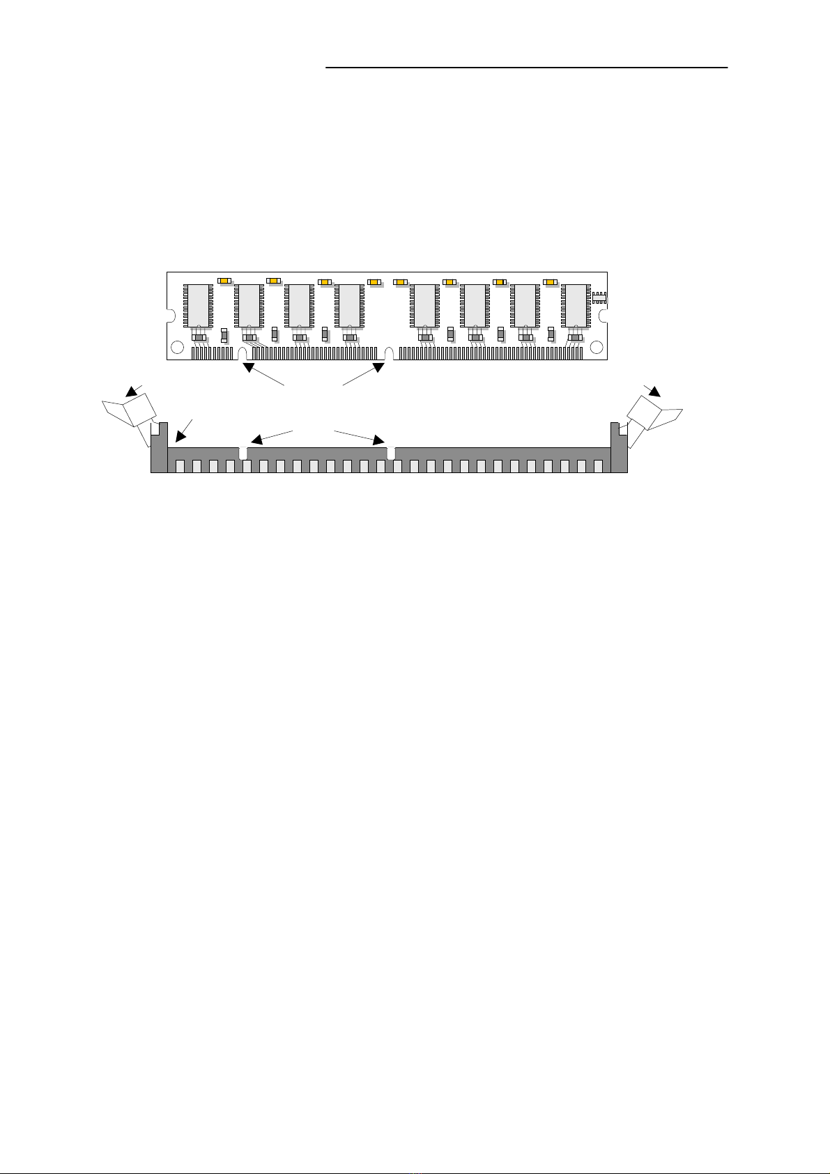
❏System Memory/RAM : Two DDR200/266 DIMM Socket, up to 2GB RAM
❏IDE Drive Interface : A. One 40-pin (2x20, 2.54mm) IDE connector that
support Ultra ATA100, build in secondary master
IDE Channel
B One 44-pin (2x22, 2mm) IDE connector that support
Ultra ATA100, build in secondary slave IDE Channel
C. One CompactFlash type II socket, support ATA
mode, build in primary master IDE Channel
❏BIOS : Awardlicensed BIOS
❏I/O Connector : A. Six external RJ-45 connectors
B. One RS-232 DB-9 connector
❏Reserved pin-header : A. Keyboard/Mouse pin-header
B LAN LED pin deader l
C. Power/Status LED header
D. 16 pin non-standard PIO x 1 for LCM connection
E. One 1*4 pin-header (for control Keypad use)
F. On board 2 pin header for software reset
❏RTC Battery : A. Internal RTC with Li battery
B. Watchdog Timer Function
❏Operating Temperature : 0 °C~60 °C
❏Storage Temperature : -20 °C~70 °C
❏Power : On-Board 20 pin ATX power connector (AT function
only)
❏Humidity : 5 %~95%RH, non-condensing
❏Dimensions : 305 x 243 mm
❏Model Extension : MB-X71A: Two 82540+Four 82551

INTRODUCTION
~ 3 ~
1.2 PACKING CHECK LIST
Inspect the product package for the following items before installation. If there is anything
missing, please contact our authorized reseller.
Item Qty Remark
MB-X71 1 pc MB-X71 Socket 478 Network security appliance control board
User‘s manual 1 pc MB-X71 user’s manual

~ 4 ~
JUMPER SETTING AND CONNECTORS
The figure below shows the jumpers and connectors location on the MB-X71 Series. The
PCB version may differ for slight changes without notice.
2.1 Board Outline of MB-X71 Series
CHAPTER 2.
SM1
PSA1
PS4P1
CFSL1
FDCA1
IDEA1
CF1
FAN3
RSW1
IDEB1
CMOS1
LAN1
PCIB1
1
11
2
43
44
1
LEDE1
LAN2
LAN3
PKMB1
7
1
8
2
Intel
LAN4
LAN5
LAN6
VGAB1
PSW1
ATJP1
LCMA1
DIMMC1
4 1
KPA1
DIMMC2
FAN
FAN
PLRS1
PCIA1
1

JUMPER SETTINGS AND CONNECTORS
~ 5 ~
2.2 INSTALLING AND UPGRADING THE CPU
To upgrade to a higher power CPU, simply remove the old CPU and install a new one.
Make sure to set the jumpers for the new CPU type and speed.
WARNING!
Disconnect the power cord from your system when you intend to
work on it or when
y
ou plan to open the chassis of your industrial
computer. Do not make connections when the power is turned on
because the sensitive electronic components could be damaged
by the sudden rush of power. Please only allow experienced
electronic technicians to do this job.
STATIC ELECTRICITY PRECAUTION!
Caution! Computer components are very sensitive to damage
from static electric discharge. Always ground yourself to remove
static charge build-up before touching the boards in the computer.
Use a grounding wrist strap at all times. Place all electroni
c
components on anti-static pad for static-dissipation or in
static-shielded bag when they are not in the chassis.
CAUTION!
Danger of explosion if battery is incorrectly replaced. Replace
only with the same or equivalent type recommended by the
manufacturer. Dispose of used batteries according to the batter
y
manufacturer’s instructions or accepted environmental regulator
y
standards.

JUMPER SETTING AND CONNECTORS
~ 6 ~
!INSTALLING THE DIMM MODULE:
A DIMM module simply snaps into a socket on the system board. Pin1 of the DIMM
module must correspond with Pin1 of the socket.
1. Pull the “tabs” which are at the ends of the socket to the side.
2. Position the DIMM above the socket with the “notches” in the module aligned with the
“keys” on the socket.
3. Seat the module vertically into the socket. Make sure it is completely seated. The tabs
will hold the DIMM in place.
Pin1
Notch
Key
TabTab

JUMPER SETTINGS AND CONNECTORS
~ 7 ~
2.3 JUMPER SETTING OVERVIEW
In order to select the operation modes of your system, configure and set the jumpers on
your SBC to match the needs of your applications. To set a jumper, a plastic cap
containing metal contacts is placed over the jumper pins as designated by the required
configuration as listed in this section. A jumper is said to be “ on ” or “ 1-2 ” when the
cap has been placed on two of its pins, as show in the figure below:
A pair of needle-nose pliers is recommended when working with jumpers. If you have
any doubts about the best hardware configuration for your application, contact our local
sales representative before you make any changes. In general, you simply need a
standard cable to make most connections

JUMPER SETTING AND CONNECTORS
~ 8 ~
2.4 JUMPER LOCATIONS FOR MB-X71 SERIES
CFSL1
CMOS1
LAN1
LAN2
LAN3
Intel
LAN4
LAN5
LAN6

JUMPER SETTING AND CONNECTORS
~ 9 ~
2.5 JUMPER SETTINGS SUMMARY FOR MB-X71 SERIES
JUMPER FUNCTION
CMOS1 Clear CMOS Data
SCF1 Master/Slave Select

JUMPER SETTING AND CONNECTORS
~ 10 ~
2.6 JUMPER SETTINGS FOR MB-X71 SERIES
" CMOS1 : Clear CMOS Data
CMOS1 Description
1-2 Normal (Default)
2-3 Clear CMOS
" SCF1:Master/Slave Select
SCF1 Compact Flash Card
1-2 Master (Default)
2-3 Slave
Clear CMOS1
Normal (Default)
CMOS1
1
2
3
1
2
3
1
2
3
SCF1
1
3

JUMPER SETTING AND CONNECTORS
~ 11 ~
2.7 I/O CONNECTOR LOCATIONS FOR MB-X71 SERIES
SM1
PSA1
PS4P1
FDCA1
IDEA1
CF1
FAN3
RSW1
IDEB1
LAN1
PCIB1
1
11
2
43
44
1
LEDE1
LAN2
LAN3
PKMB1
7
1
8
2
Intel
LAN4
LAN5
LAN6
VGAB1
PSW1
ATJP1
LCMA1
DIMMC1
4 1
KPA1
DIMMC2
FAN
FAN
PLRS1
PCIA1
1

JUMPER SETTING AND CONNECTORS
~ 12 ~
2.8 I/O CONNECTOR SUMMARY FOR MB-X71 SERIES
CONNECTOR FUNCTION
FAN1-3 3 Pin Fan Connector
LANA1~2 Type 1 ( RJ-45 )
LANA3~6 :Type 1 ( RJ-45)
COM1 RS232 Serial Port #1 Connector (D-Sub)
PKMB1 PS/2 Keyboard & Mouse Connector (2x4 Header 2.54mm )
PSA1 20 Pin ATX Power Connector
PS4P1 4-Pin Power Connector (P4-4P Male )
KPA1 LCM Keypad
LCMA1 LCM CONNECTOR
VGAB1 External VGA Connector ( 12 Pin Header )
IDEA1 IDE Interface Connector ( 44 Pin 2.0mm Pitch Header )
IDEB1 IDE Interface Connector ( 40 Pin 2.54mm Pitch Header )
PLRS1 Power LED, Reset, Speaker Connector
FDCA1 Floppy Interface Connector (34 Pin Header)
CF1 Compact Flash Connector
LEDE1 2x22 Pin
PCIB1 124 Pin Mini PCI Socket

JUMPER SETTING AND CONNECTORS
~ 13 ~
2.9 I/O CONNECTORS DESCRIPTION
" FAN1~3 : 3 Pin FAN Connector
Pin No. Description
1 Ground
2 +12V
3 FAN Status
" LANA1~2 :Type 1 ( RJ-45 )
Description
Pin No. Fast Ethernet Giga Ethernet
1 TX+ MD0+
2 TX- MD0-
3 RX+ MD1+
4 T45 MD2+
5 T45 MD2-
6 RX- MD1-
7 T78 MD3+
8 T78 MD3-
" LANA3~6 :Type 1 ( RJ-45)
Pin No. Description
1 TX+
2 TX-
3 RX+
4 T45
5 T45
6 RX-
7 T78
8 T78
FAN1
123
LANA1~2
LANA3~6

JUMPER SETTING AND CONNECTORS
~14~
" COMA1: RS-232 Serial Port #1 Connector ( D-Sub )
Pin No. Description
1 Data Carrier Detect ( DCDA # )
2 Receive Data ( RXDA )
3 Transmit Data ( TXDA )
4 Data Terminal Ready ( DTRA # )
5 Ground ( GND )
6 Data Set Ready ( DSRA # )
7 Request To Send ( RTSA # )
8 Clear To Send ( CTSA # )
9 Ring Indicator ( RIA # )
" PKMB1:PS/2 Keyboard & Mouse Connector (2x4 Header 2.54mm )
Pin No. Description Pin No. Description
1 KBCLK 2 GND
3 NC 4 KBDATA
5 NC 6 MSDATA
7 MSCLK 8 VCC
" PSA1:20 Pin ATX Power Connector
Pin No. Description Pin No. Description
1 +3.3V 11 +3.3V
2 +3.3V 12 -12V
3 GND 13 GND
4 +5V 14 SWITCH
5 GND 15 GND
6 +5V 16 GND
7 GND 17 GND
8 Power Good 18 -5V
9 Stand-By 5V 19 +5V
10 +12V 20 +5V
COMA1
1 5
96
2
4
6
8
1
3
5
7
PKMB1
PSA1

JUMPER SETTING AND CONNECTORS
~ 15 ~
" PS4P1:4-Pin Power Connector (P4-4P Male )
Pin No. Description
1 GND
2 GND
3 +12V
4 +12V
" KPA1:LCM Keypad
Pin Description
1 KPA1
2 KPA2
3 KPA3
4 KPA4
" LCMA1:LCM CONNECTOR
Pin Description Pin Description
1 VCC 2 PGND
3 LSTIN- 4 VEE
5 LAFD- 6 LINIT-
7 LPD1 8 LPD0
9 LPD3 10 LPD2
11 LPD5 12 LPD4
13 LPD7 14 LPD6
15 LCD 16 VCC
" VGAB1 : External VGA Connector ( 12 Pin Header )
Pin No. Description Pin No. Description
1 R 2 Ground
3 G 4 Ground
5 B 6 Ground
7 H-SYNC 8 Ground
9 V-SYNC 10 Ground
11 Detect-display Data 12 Deteck-display CLOCK
1
3
4
2
PS4P1
KPA1
4
1
2
16
15
1
LCMA1
VGAB1
11
122
1

JUMPER SETTING AND CONNECTORS
~16~
" IDEA1 : IDE Interface Connector ( 44Pin 2.0mm Pitch Header )
Pin No. Description Pin No. Description
1 Reset # 2 Ground
3 Data 7 4 Data 8
5 Data 6 6 Data 9
7 Data 5 8 Data 10
9 Data 4 10 Data 11
11 Data 3 12 Data 12
13 Data 2 14 Data 13
15 Data 1 16 Data 14
17 Data 0 18 Data 15
19 Ground 20 NC
21 DMA REQ # 22 Ground
23 IOW # 24 Ground
25 IOR # 26 Ground
27 IOCHRDY 28 Ground
29 DMA ACK # 30 Ground
31 Interrupt 32 NC
33 SA 1 34 NC
35 SA 0 36 SA 2
37 HDC CS 0# 38 HDC CS 1#
39 HDD Active 40 Ground
41 VCC 42 VCC
43 Ground 44 NC
2 44
IDEA1
1 43
Other Lanner electronics PCI Card manuals
Popular PCI Card manuals by other brands

National Instruments
National Instruments PCI-FBUS installation guide

Avermedia
Avermedia ER330 quick start guide

Buffalo
Buffalo NFinity WLI-PCI-G300N Specifications

Avermedia
Avermedia DVD EZMaker 7 Quick installation guide

Draytek
Draytek VigorNIC 132 series user guide

Hama
Hama 00053121-V2 Operating instruction