Lascar DMM 350 Assembly instructions
MINI DIGITAL MULTIMETER - DMM 350
OPERATOR'S INSTRUCTION MANUAL
www.lascarelectronics.com
LASCAR ELECTRONICS LTD.
MODULE HOUSE, WHITEPARISH, WILTSHIRE SP5 2SJ UK
TEL: +44 (0)1794 884567 FAX: +44 (0)1794 884616 E-mail: sales@lascar.co.uk
LASCAR ELECTRONICS INC.
LASCAR ELECTRONICS (HK) LIMITED
3750 West 26th Street, Erie, PA 16506 USA
FLAT C, 5/FL., LUCKY FTY. bldg., 63-65 HUNG TO ROAD, KWUN TONG, KOWLOON, HONG KONG

2
WARNING
GENERAL
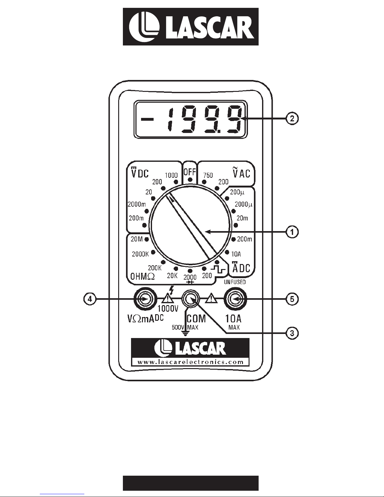
FRONT PANEL DESCRIPTION
1. FUNCTION/RANGE Switch
2. Display
3. COMMON Socket
4. “V mA” Socket
5. “10A” Socket (for 10 seconds only)
GENERAL
READ AND UNDERSTAND THIS MANUAL BEFORE USING THE INSTRUMENT. Failure
to understand or comply with the WARNINGS and operating instructions can result in
serious or fatal injuries and/or property damage.
Before attempting to operate the instrument, become familiar with each control. A
thorough understanding of how the instrument operates will avoid undue mistakes and
minimise measurement errors, instrument damage and the possibility of personal injury.
This section, consisting of the Figure, will describe the proper function of the instrument.
This control is located in the centre of the front panel and it combines the operations of
selecting the function and desired range, as well as having an “OFF” position. To extend the
life of the battery, the switch should be in this “OFF” position when the instrument is not in
use.
3½ digit LCD, 7-segment, 0.5” digit height.
Plug-in connection for Black (negative) test lead.
Plug-in connection for Red (positive) test lead for all voltage and resistance and DC current
(except 10A) measurements.
Plug-in connection for Red (positive) test lead for DC 10A measurements.
Display: 3½ digit LCD, 0 5” digit height, with auto polarity
Overrange indication: 3 least significant digits blanked
Temperature for specified accuracy: 23 °C ±5 °C RH<75%
Temperature ranges: Operating: 0 °C to 40 °C (32°F to 104°F)
Storage: -10 °C to 50 °C (14°F to 122°F)
Power: 9V alkaline or carbon-zinc battery
Low battery indication: BAT on left of LCD display
Dimensions (H x W x D): 128 x 70 x 28mm (5” x 2.75” x 1.2”)
Net weight: 210g. (8oz)
Ω
.
SPECIFICATIONS

3
DC VOLTAGE (DCV)
DC CURRENT (DCA)
AC VOLTAGE (ACV)
RESISTANCE
DIODE TEST ( )
SIGNAL INJECTOR ( )
Range Resolution Accuracy
Range Resolution Accuracy
Range Resolution Accuracy
Range Resolution Accuracy
200mV 100 V
2000mV 1mV
20V 10mV ±(1% reading + 6 counts)
200V 100mV
1000V 1mV ±(1.5% reading + 8 counts)
Maximum allowable input: 1000V DC or peak AC.
200uA 100nA
2000uA 1 A
20mA 10 A ±(1.2% reading + 8 counts)
200mA 100
10A 10mA ±(1.2% reading + 10 counts)
Overload Protection: mA input 2A/250V fuse.
200V 100mV (1.2% reading + 20 counts)
750V 1V
Frequency Range: 45Hz - 450Hz
Maximum Allowable Input: 750Vrms
Response: Average responding. Calibrated in rms of a sine wave.
200 100m
2000 1 ±(1.2% reading + 8 counts)
20k 10
200k 100
2000k 1k
20M 10k ±(2% reading + 10 counts)
Maximum Open Circuit Voltage: 2.8V
Measures forward voltage drop of a semiconductor junction in mV, test current of 1.5mA
maximum.
Outputs a square wave signal (30-40Hz) for audio check.
µ
µµµ
ΩΩ
ΩΩ
ΩΩ
ΩΩ
ΩΩ
ΩΩ
+

OPERATING INSTRUCTIONS
GENERAL
WARNINGS
DC VOLTAGE MEASUREMENT (DCV)
DC CURRENT MEASUREMENT (DCA)
AC VOLTAGE MEASUREMENT (ACV)
RESISTANCE MEASUREMENT ( )
The meter is a digital multimeter designed for engineers and hobbyists. Equipped with
functions and 19 ranges, each test position is quickly and easily selected with a simple turn
of the FUNCTION/RANGE selector rotary switch.
1. To avoid electrical shock hazard and/or damage to the instrument, do not measure
voltages that might exceed 1000V DC or 750V AC peak above earth ground.
2. Before using the instrument, inspect the test leads, connectors and probes for cracks,
breaks or creases in the insulation.
1. Connect the Red test lead to the “V mA” socket and the black test lead to the “COM”
socket.
2. Set the FUNCTION/RANGE switch to the desired DCV position. If the magnitude of the
Voltage is not known, then set the switch to the highest range and reduce it until a
satisfactory reading is obtained.
3. Connect the test leads to the device or circuit under test.
4. Turn on power to the device or circuit under test. The voltage value will appear on the
LCD Display along with the voltage polarity.
1. Connect the Red lead to the “V mA” socket for measurements up to 200mA and
connect the black lead to the “COM” socket.
For measurements between 200mA and 10A, connect the Red lead to the 10A
socket (for 10 seconds only).
2. Set the FUNCTION RANGE switch to the desired DCA position.
3. Open the circuit to be measured, and connect the test leads IN SERIES with the load in
which the current is to be measured.
4. Read the current value on the LCD display.
1. Connect the Red lead to the “V mA” socket and the Black lead to the “COM” socket.
2. Set the FUNCTION/RANGE switch to the desired ACV position.
3. Connect the test leads to the device or circuit under test.
4. Read the voltage value on the LCD Display.
1. Connect the Red lead to the “V mA” socket and the Black lead to the “COM” socket.
2. Set the FUNCTION RANGE switch to the desired position.
3. If the resistance being measured is connected to a circuit, turn off the power and
discharge all capacitors before applying the test leads.
4. Connect the test leads to the circuit being measured.
5. Read the resistance value on the LCD Display.
5
Ω
Ω
Ω
ΩΩ
NOTE:
Ω
4
5
DIODE TEST ( )
SIGNAL INJECTOR ( )
CAUTION
CALIBRATION PROCEDURE
1. Connect the Red lead to the “V mA” socket and the Black lead to the “COM” socket.
2. Set the FUNCTION RANGE switch to the diode (2000 position.
3. Connect the Red lead to the anode of the diode and the black lead to the cathode.
4. Read the forward voltage drop in mV on the LCD Display. If the polarity is reversed, "1"
will be displayed.
1. Connect the Red lead to the “V mA” socket and the Black lead to the “COM”
socket.
2. Set the FUNCTION RANGE switch to the (square wave) position.
3. A test signal (30-40Hz) will appear between the “V mA” and “COM” sockets with a
certain DC component. An additional coupling capacitor should be used.
BEFORE ATTEMPTING BATTERY REPLACEMENT, DISCONNECT THE TEST LEADS
FROM ANY ENERGISED CIRCUITS TO AVOID SHOCK HAZARD.
In all cases first remove meter from its protective holster.
Fuses rarely need replacement and always blow as a result of operator error. To replace the
fuse, remove the 2 back cover fixing screws, carefully remove the back cover and replace
the blown fuse with one with the same rating, replace the back cover and fixing screws.
To replace the battery, remove the battery door screw and battery door, replace with a new
battery of the same type and refit the battery door and retaining screw.
Recalibration should not be necessary for long intervals in any event. Calibration must be
carried out with a highly accurate voltage standard (better than 0.1% accuracy).
1. Remove the 2 back cover fixing screws. Carefully remove the back cover.
2. With the instrument operating and set to the 200mV DC range, apply 190mV DC from
an accurate source.
3. With a small screwdriver inserted into the semi-fixed resistor (SVR-1), carefully turn it
until the reading reads 190.0mV.
4. Refit the back cover and retaining screws.
Replace multimeter into protective holster when calibration or battery/fuse replacement is
complete.
ΩΩ)
Ω
Ω
FUSE AND BATTERY REPLACEMENTS
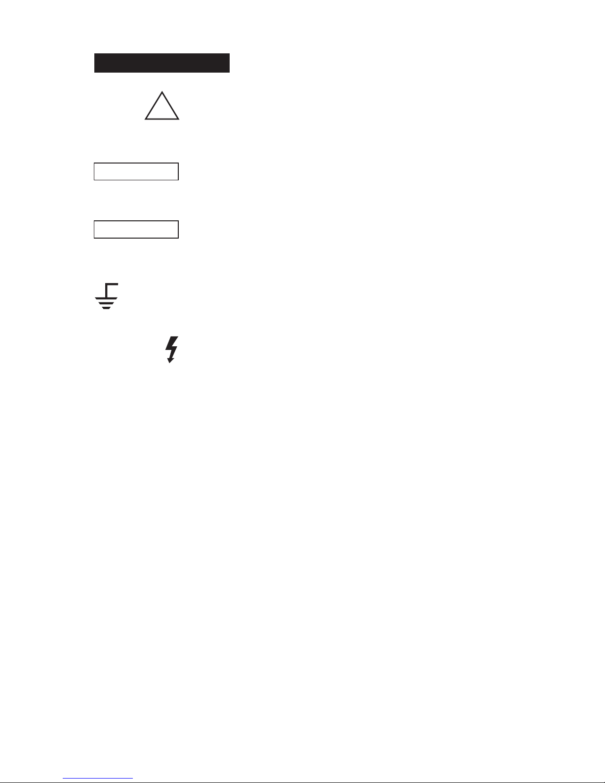
SAFETY SYMBOLS
This marking adjacent to another marking or a terminal or operating
device indicates that the operator must refer to an explanation in the
operating instructions to avoid damage to the equipment and/or to
avoid personal injury.
This WARNING sign notes a hazard. It calls attention to a procedure,
practice or the like which, if not correctly performed or adhered to,
could result in permanent injury.
This CAUTION sign denotes a hazard. It calls attention to a
procedure, practice or the like which, if not correctly adhered to,
could result in damage to or destruction of part of the instrument.
This marking advises the user that the terminals so marked must not
be connected to a circuit point at which the voltage, with respect to
earth ground, exceeds (in this case) 500 volts.
This symbol adjacent to one or more terminals identifies them as
being associated with ranges that may in normal use be subjected to
particularly hazardous voltages. For maximum safety, the instrument
and its test leads should not be handled when these terminals are
energized.
!
500V MAX
WARNING
CAUTION
6
Table of contents
Popular Multimeter manuals by other brands


Gossen MetraWatt
Gossen MetraWatt METRAmax 6 operating instructions

PeakTech
PeakTech 4000 Procedure of calibration

YOKOGAWA
YOKOGAWA 90050B user manual

Gossen MetraWatt
Gossen MetraWatt METRALINE DMM16 operating instructions

Fluke
Fluke 8846A Programmer's manual

Tempo Communications
Tempo Communications MM200 instruction manual


