Lauda Versafreeze VF 15040 User manual

Operating Instructions
Versafreeze Freezer Cabinets
VF 15040, VF 60040, VF 70040, VF 15085, VF 60085, VF 70085

2 / 44 Versafreeze Freezer Cabinets 07/2021

07/2021 Versafreeze Freezer Cabinets 3 / 44
LAUDA-GFL Versafreeze Freezer Cabinets for the long-term storage of organic substances, for example, operate silently
and with exceptional reliability. Insulation consisting of vacuum insulation panels and polyurethane foam is the key to its eco-
nomical energy consumption.
The refrigeration compartment is made entirely of stainless steel.
The refrigeration system incorporates fully hermetic, air-cooled high-performance compressors and is maintenance-free.
Freezer cabinet models VF 15040, VF 60040, VF 70040 can be set to temperatures as low as -40 °C.
Freezer cabinet models VF 15085, VF 60085, VF 70085 can be set to a temperature between -50 °C and -85 °C, and
offer the best temperature stability in relation to the set temperature.
Before installing the appliance, please check the content of the delivery for completeness and integrity.
If you discover damage or have any complaints, please get in touch with your supplier or contact us directly.
LAUDA-GFL Gesellschaft für Labortechnik mbH
Schulze-Delitzsch-Str. 4+5
30938 Burgwedel - Germany
Phone: +49 (0)5139 9958 0
Fax: +49 (0)5139 9958 21
E-mail: info@lauda-gfl.de
Internet: www.lauda.de/de/lauda-gfl

4 / 44 Versafreeze Freezer Cabinets 07/2021

07/2021 Versafreeze Freezer Cabinets 5 / 44
Table of contents
Operating Instructions .....................................................................................................................................................................1
1Using the freezer cabinets........................................................................................................................................................7
Intended use.....................................................................................................................................................................7
Improper use ....................................................................................................................................................................7
2Warranty ...................................................................................................................................................................................7
3Before starting up.....................................................................................................................................................................7
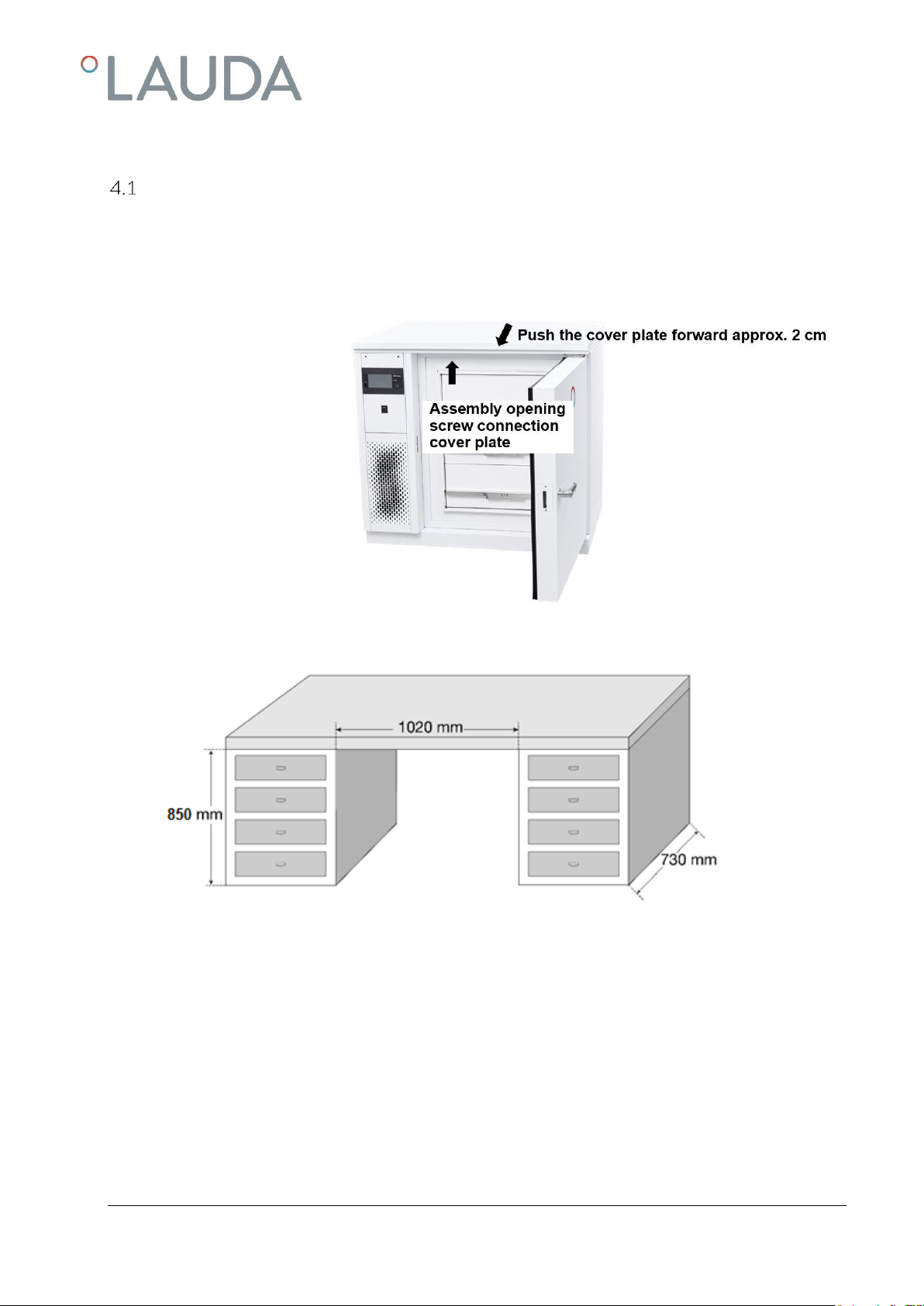
4Location of the freezer cabinet ...............................................................................................................................................8
Under table installation (only applies for VF 15040 and VF 15085)......................................................................9
5Operating voltage and electrical connection......................................................................................................................10
6Commissioning ......................................................................................................................................................................11
Operating and display elements on the touch screen unit........................................................................................12
Switching the appliance on and off..............................................................................................................................14
Selecting a user profile .................................................................................................................................................14
Managing access rights for user profiles (login and user profile display) .................................................................14
6.4.1
Switching the appliance on and off.....................................................................................................................15
Language selection .......................................................................................................................................................16
Refrigeration compartment temperature set point...................................................................................................16
Changing the password ................................................................................................................................................17
7Function description .............................................................................................................................................................18
Function of data logger, history...................................................................................................................................18
Data transfer via USB ..................................................................................................................................................19
Internet connection......................................................................................................................................................19
7.3.1
Entering e-mail addresses for forwarding alarms..............................................................................................19
7.3.2
E-mail configuration............................................................................................................................................20
7.3.3
Alarm management .............................................................................................................................................20
Optional Water cooling................................................................................................................................................21
7.4.1
Setting the cooling water volume regulator.......................................................................................................22
8Alarm limit values..................................................................................................................................................................23
Setting a limit value for the door alarm delay .............................................................................................................23
Overtemperature limit value........................................................................................................................................23
Low temperature limit value.........................................................................................................................................23
USr User level ...............................................................................................................................................................23
Alarm and potential-free contact ...............................................................................................................................24
Resetting an alarm ........................................................................................................................................................24
Probe monitoring..........................................................................................................................................................24
Overtemperature or low temperature alarm..............................................................................................................24
Mains power failure.......................................................................................................................................................24
Battery fault alarm (internal battery)..........................................................................................................................24
9Care and maintenance..........................................................................................................................................................25
Defrosting......................................................................................................................................................................25
Technical support..........................................................................................................................................................25

6 / 44 Versafreeze Freezer Cabinets 07/2021
10 Disposing of old appliances .................................................................................................................................................. 25
11 Technical data........................................................................................................................................................................ 26
12 Circuit diagram...................................................................................................................................................................... 28
13 Spare parts list ....................................................................................................................................................................... 34
Freezer cabinet VF 15040 / VF 15085.................................................................................................................. 34
Freezer cabinet VF 60040, VF 60085 / VF 70040, VF 70085....................................................................... 36
Elektrical Switchgear.................................................................................................................................................... 38
14 Auxiliary equipment.............................................................................................................................................................. 39
Data logger for monitoring and recording refrigeration compartment temperature ............................................. 39
Storage system ............................................................................................................................................................. 39
14.2.1
Racks with drawers .............................................................................................................................................. 39
14.2.2
Racks with loading from the side........................................................................................................................ 40
14.2.3
Boxes .................................................................................................................................................................... 40
14.2.4
Grid dividers ......................................................................................................................................................... 40
15 Notes...................................................................................................................................................................................... 41

07/2021 Versafreeze Freezer Cabinets 7 / 44
1Using the freezer cabinets
Intended use
LAUDA Versafreeze Freezer Cabinets can be set to temperatures between 0 °C and –85 °C, depending on the version.
The Freezer Cabinets are intended for the long-term storage of organic substances, for example.
In order to guarantee that the freezer cabinet functions perfectly, always read and observe the information
in these operating instructions. Only persons familiar with these operating instructions are permitted to
install and operate the appliances.
Caution:
Due to the low temperatures in the refrigeration compartment, suitable protective gloves must always
be worn when storing and retrieving refrigerated goods. Arms must also be covered.
Improper use
LAUDA Versafreeze Freezer Cabinets are not suitable for the long-term storage of food and beverages, or similar prod-
ucts. The storage of highly flammable and/or explosive substances is forbidden.
The freezer cabinet must not be installed or operated in laboratory areas with aggressive or corrosive ambient conditions.
Aggressive media such as hydrochloric acid may not be heated or evaporated in the immediate vicinity or inside the appli-
ance itself. The freezer cabinet must not be operated in hazardous areas.
LAUDA Freezer Cabinets used in laboratories are not classified as medical devices. They are not subject to national or in-
ternational medical device law and must be used accordingly.
2Warranty
All laboratory equipment and accessories from LAUDA-GFL Gesellschaft für Labortechnik mbH are subject to warranty
claims, including repairs, installation and spare parts. In order to identify faulty appliances, we need the type designation
and the serial number from the type plate located at the top left of the right side wall of the freezer cabinet and possibly a
copy of the invoice.
3Before starting up
In order to guarantee that the freezer functions perfectly, always read and observe the information in these operating in-
structions. Safety instructions are identified by the following warning symbols.
Read and observe the
operating instructions
Caution!
Flammable refrigerant
(hydrocarbons)
Warning of
cold surfaces
Warning of dangerous
electrical voltage
General
hazard warning
Warning indicating
crushing of hands

8 / 44 Versafreeze Freezer Cabinets 07/2021
Disconnect all poles on the appliance
from the power supply before
commencing maintenance and repair work
(pull the mains plug).
The warranty does not cover the free repair of malfunctions resulting from improper installation and handling.
Only trained and qualified personnel are permitted to perform service and repair work on refrigeration
equipment. In the event of repair work, the refrigerant quantity must not exceed the initial fill quantity.
See the type plate for quantity information and material specifications.
Before soldering work is carried out on the refrigeration system, the refrigerant must be drained com-
pletely and the system blown through with dry nitrogen. Only trained and qualified personnel are permit-
ted to dispose of refrigerant and removed components.
Caution: flammable refrigerant (hydrocarbons)
Due to the nature and quantity of the refrigerants used, naked flames are prohibited within a radius of 1 m
of the appliance.
Removed components bearing this marking must be disposed of separately.
4Location of the freezer cabinet
Always install the appliance on a solid, flat, horizontal indoor surface. The installation room must be at least 24 m³ in size.
Alternatively, the installation room must be ventilated. Freezer appliances must be positioned a minimum of 150 mm
away from other appliances or walls so that the aspirated cooling air can circulate freely. The condenser on the back of the
appliance must not be obstructed or blocked in.
The ambient temperature must not exceed +28 °C, as this would reduce the cooling capacity of the appliance and in-
crease the temperature in the refrigeration compartment. Effective ventilation in the installation room is usually sufficient
to lower the temperature.
The appliance is not intended for use in areas with an explosion hazard, such as during anesthesia using flammable gases or
vapors. Please refer to the technical data for information on the appliance protection level.

07/2021 Versafreeze Freezer Cabinets 9 / 44
Under table installation (only applies for VF 15040 and VF 15085)
The cover panel on the deep-freeze appliance must be removed prior to installation under a tabletop. When the appliance
door is open, you can reach the screw connection for the cover by inserting a Phillips screwdriver through the opening on
the right side of the upper housing frame. After loosening the screw, pull the cover panel approx. 2 cm forward and then
lift from the appliance.
Please refer to the illustration below for the minimum dimensions for under table installation.
Before the appliance is moved to its place of installation, the electrical system (see point 5 of these instructions) and, if
necessary, the alarm system (see point 8.5) must be connected. Ensure that the connection cable is not damaged when
the freezer appliance is moved.

10 / 44 Versafreeze Freezer Cabinets 07/2021
Freezer cabinets installed under tabletops must be positioned a minimum of 60 mm away from other appliances or walls so
that the aspirated cooling air can circulate freely. Once the freezer cabinet has been moved to its place of installation, it
must be secured in position with the locking feet. The locking feet are positioned at a distance of approx. 40 mm from
the side walls under the front of the appliance. Use the wrench supplied to unscrew the feet by turning clockwise until they
are resting securely on the ground. It should now no longer be possible to move the appliance on the casters.
Caution!
Due to the nature and quantity of the refrigerants used, naked flames are prohibited within a radius of 1 m
of the appliance.
5Operating voltage and electrical connection
A marked equipotential bonding connection is located on the back of the freezer cabinet. Local regulations may stipulate
the need to connect the appliance to a grounding network for equipotential bonding. Please check before commissioning
the appliance.
The operating voltage and the mains frequency on the type plate (right side wall, top left) must
match the power supply specifications.
The main switch on the refrigeration system must switched off (position 0). Once these conditions
have been met, establish the electrical connection.
The refrigeration system may only be operated on a correctly installed power connection with a protective
earth conductor (PE) that complies with local regulations.
It must be possible to disconnect all poles of the power supply from the power network (e.g. via an earthed
socket or switch).
Off
On

07/2021 Versafreeze Freezer Cabinets 11 / 44
6Commissioning
Caution:
Due to the low temperatures in the refrigeration compartment, suitable protective gloves must al- ways
be worn when storing and retrieving refrigerated goods. Arms must also be covered.
Caution:
Do not leave the freezer cabinet keys near the appliance or within the reach of children.
Do not store acids and alkalies that can erode the materials, hazardous substances that emit harmful va-
pors, or highly flammable and/or explosive substances inside the appliance
(DGUV Information 213-850).
Read and observe the operating instructions.

12 / 44 Versafreeze Freezer Cabinets 07/2021
Operating and display elements on the touch screen unit
The three large colored symbols on the left of the display indicate the ACTUAL temperature at the most important points
on the appliance: the refrigeration compartment (blue field) and condenser (purple field), while the orange field shows the
voltage of the internal battery. The bottom line on the display indicates whether the appliance is a single-stage or dual-
stage device. Rotating symbols indicate that the compressors or internal fan on the condenser are operating. The other
symbols have the following meaning:
ON / OFF Alarm
Menu Cloud connection
Login and user profile display Back one
Level Controller Data logger, history
Settings / Controller settings
LED status indicator
(see table below)

07/2021 Versafreeze Freezer Cabinets 13 / 44
Normal refrigeration LED 1 and auxiliary device LED 2
Status
No.
LED 1
i symbol
Description
1
green
active and no fault during normal refrigeration
2
red
All other cases, including:
Connection failure
Collective fault
Standby
Status
No.
LED 2
Snowflake symbol
Description
1
green
active and no fault in the auxiliary device
2
yellow
Refrigeration compartment temperature is too high. Safety cooling (auxiliary
device) is on standby.
Solenoid valve will be activated "soon” and no fault in the auxiliary device.
"Soon" means: Refrigeration compartment temperature is within the hysteresis
range around the resulting set point (between lower and upper switching point)
and solenoid valve is not active.
3
yellow, flashing
Solenoid valve active (coolant (CO2 or LN2) is injected), no fault in the auxil-
iary device. Coolant is only injected when the door is closed.
4
off
No auxiliary device connected.
5
red
All other cases, including:
Collective fault
Standby

14 / 44 Versafreeze Freezer Cabinets 07/2021
Switching the appliance on and off
The appliance can only be switched on and off from the user profile "User" (see points 6.3 and 6.4 in the operating in-
structions). Switch on the appliance by setting the main switch (see point 5 of the operating instructions) to position "I".
Approx. 5 seconds after the control element has booted up, the overtemperature Tmax 1 alarm appears on the display and
the alarm signal sounds. Acknowledge the alarm on the display.
Selecting a user profile
To select a user profile such as User (point 6.4 of the operating instructions), tap the "Login" symbol and user
profile display. Tap the desired user profile to select it, enter the relevant password for the selected profile
(point 6.4. of the operating instructions) and press save to exit the screen.
Managing access rights for user profiles (login and user profile display)
Admin 1
All settings required to integrate the freezer into the operator's IT landscape, for example, can be configured under the
user ID Admin1. The default password is "Admin 1".
Guest
The freezer appliance is started under the user ID "Guest". All relevant operational data can be accessed on this level. It is
not possible to switch the appliance on and off or modify settings on this level. The default password is "Guest".
User
Users logged in to the "User" profile can configure settings such as those for switching the appliance on and off as well as
the refrigeration compartment temperature set point and the alarm delay for the door. The default password is "User".
Service
Under the "Service" user ID, the operator/user can modify more advanced settings than those on the "User" level,
including changing parameters or set point temperature limits and transferring data via USB. The default password is "Ser-
vice".

07/2021 Versafreeze Freezer Cabinets 15 / 44
ADMIN
All data and settings that were preset by the manufacturer of the freezer appliance, such as the permitted or possible set
point limits for the refrigeration compartment temperature, are stored under the "ADMIN" user profile. The operator
cannot modify the settings in this profile.
6.4.1 Switching the appliance on and off
Once the user profile has been changed, the display switches to the start screen. Touch VF XXXYY on the display to
switch to the controller view. Press the ON/OFF symbol on the touch screen unit. The temperature and "collective
alarm" appear on the display. Acknowledge the alarm.
To switch off the appliance, first press the ON/OFF symbol on the touch screen unit and then set the main switch to
position 0.
Caution:
To switch off the freezer cabinet for longer periods, press the ON/OFF symbol on the touch screen unit
until OFF appears on the display and then set the main switch to position 0.
If the alarm contact of the alarm system (see point 7 of the operating instructions) is connected to an in-
house fault monitoring system, an alarm is triggered when the cabinet is switched off.
Inform the office responsible for monitoring faults well in advance that you intend to switch off the freezer cabinet.
Caution:
If the appliance is only switched off at the main switch, the "power failure" alarm triggers and the appliance
records the temperature inside the cabinet for approx. 35 hours, powered by the internal battery.

16 / 44 Versafreeze Freezer Cabinets 07/2021
Language selection
The only languages currently available are German and English
Proceed as follows:
Menu
Settings
Language
After selecting the language, press the switch below
the additional LED display. Touch VF XXXYY on the display
to switch to the controller view.
Refrigeration compartment temperature set point
Once the refrigeration device has been switched on at the
main switch and the touch screen unit (see above), the dis-
play shows the current temperature in the refrigeration com-
partment. The temperature controller switches on the com-
pressors to start the cooling process so that the refrigeration
compartment reaches the set point temperature. The refrig-
eration compartment temperature display remains red until
the set point temperature is reached. When the set point is
reached, the display color changes to white. If a fault occurs
on the appliance, the display changes back to red.
The refrigeration compartment temperature set point can be
modified by tapping the symbol for the refrigeration com-
partment temperature set point. Select the required tem-
perature in the refrigeration compartment by sliding the cur-
sor or pressing the "-" or "+" symbol, and then press the save
button to store the refrigeration compartment temperature
set point.

07/2021 Versafreeze Freezer Cabinets 17 / 44
Changing the password
Only the passwords for a specific user profile and all subordinate levels can be changed from the relevant user profile. An
Admin1 can change all passwords, a User can only change the passwords for a subordinate Guest. The number of stars in
the yellow padlock at the top of the screen indicates which user profile is currently active.
The Admin1 padlock contains three stars, Service two stars, User one star, and Guest no stars. Tap the menu symbol to
change the password for a user profile.
Menu
User management
User
Then tap user management and select the relevant user. Tap the input symbol , enter the "old password" and save. The
display changes to "Password". Enter and save the new password, then touch the symbol for one level back twice to display
the controller view.

18 / 44 Versafreeze Freezer Cabinets 07/2021
7Function description
LAUDA Versafreeze freezer cabinet models VF 15040, 60040 and 70040 are equipped with a high-performance
com- pressor and operate within a variable temperature range of -0 °C to -40 °C. Models VF 15085, 60085, and
70085 are equipped with two high-performance compressors and operate at a temperature range of -50 °C to -85 °C.
The air- cooled condenser on the back of the appliance releases heat extracted from the refrigeration compartment into
the room. The temperature controller maintains a constant temperature in line with the preset value.
The current temperature in the refrigeration compartment is shown on the controller display.
Function of data logger, history
The data logger starts automatically and records the temperature in the refrigeration compartment, the condenser tem-
perature, and the internal battery voltage every 120 seconds. Different views, e.g. days or hours, can be selected by tap-
ping the "Data logger, history" symbol.
To view past events, tap the symbol to open a window for setting the start and end dates. Now choose the desired
start and end dates, tap to select, then press OK to confirm. Tap an hour or day to return to the current display. The data
logger is fitted with a 1 GB industrial SD card and can therefore record data for 2 years before the memory is full. When
the memory is full, the oldest data is overwritten first so that only the most recent data is retained. We recommend ex-
porting the data, e.g. every six months, depending on its importance, or performing more regular backups (see Data trans-
fer via USB).
Selection of displayed control curves:
Briefly tapping the symbols An1, A2F, or ba1 shows the designation of the symbols on the left of the display.
All three control curves are selected by default. In order to display only one control curve, the other control curves must
be deactivated. To deactivate a control curve, press the corresponding symbol and hold for approx. 3 seconds. The symbol
turns white and the control curve disappears. To activate the control curve, press the deactivated white symbol and hold
for approx. 3 seconds until it reverts back to its original color.
Blue (An1) = Refrigeration compartment (compartment temperature)
Purple (A2F) = Condenser (condenser temperature)
Orange (ba1) = Battery (internal battery voltage)

07/2021 Versafreeze Freezer Cabinets 19 / 44
Data transfer via USB
In order to carry out a data transfer, the Service or Admin1 user profile must be selected. Proceed as follows:
Select Menu
Select USB
Select Export history
Insert USB stick. After the USB stick has been recognized, tap the save symbol.
After transferring the data, save and remove the USB stick
Internet connection
The touch control unit can also send alarms by e-mail. Different e-mail addresses and an e-mail server can be configured
for this purpose.
7.3.1 Entering e-mail addresses for forwarding alarms
In order to configure e-mail addresses, the Admin 1 user profile must be selected. E-mail configuration is used to forward
alarms via e-mail.
Pressing the:
Menu
E-mail configuration
Address book
Buttons opens the address book clicking the "Add" symbol opens the recipient window, where you can enter the name and
e-mail address of the individuals who should receive e-mail notification of an alarm. Click Save to add the recipient.

20 / 44 Versafreeze Freezer Cabinets 07/2021
7.3.2 E-mail configuration
Pressing the:
Menu
E-mail configuration
E-mail server
buttons opens a window for configuring your e-mail server settings. Save your entries before exiting.
7.3.3 Alarm management
Since all alarms indicating a possible fault may impact the proper operation of the appliance, we always recommend select-
ing Alarm 1 or Alarm 2 rather than the Warning setting.
Pressing the:
Menu
Alarm management
Alarm 1
buttons opens the alarm management settings. Tapping the "Add" button opens the Controller window. Select the checkbox next
to VFXXXYY in this window and then save. The New configuration window then opens, where you can select individual alarms or
tap the symbol to select all alarms. To give the configuration a name, tap the symbol, enter the name, and save. A win-
dow with the name you assigned then opens. Tapping the "E-mail" button opens the Recipient window. Tap the white button next
to the name in this window. A selection window containing the previously entered e-mail addresses opens. Select the required e-
mail address and save. Press the symbol to return to the screen view.
This manual suits for next models
5
Table of contents