LaView HD-SDI Bullet Camera User manual

0
Camera
HDSIR Bullet Camera
User Manual

HD-SDI IR Bullet Camera·User Manual
1
1
Thank you for purchasing our product. If there are any questions, or
requests, please do not hesitate to contact the dealer.
This manual may contain several technical incorrect places or
printing errors, and the content is subject to change without notice.
The updates will be added to the new version of this manual. We will
readily improve or update the products or procedures described in
the manual.
DISCLAIMER STATEMENT
“Underwriters Laboratories Inc. (“UL”) has not tested the
performance or reliability of the security or signaling aspects of this
product. UL has only tested for fire, shock or casualty hazards as
outlined in UL’s Standard(s) for Safety, UL60950-1. UL Certification
does not cover the performance or reliability of the security or
signaling aspects of this product. UL MAKES NO REPRESENTATIONS,
WARRANTIES OR CERTIFICATIONS WHATSOEVER REGARDING THE
PERFORMANCE OR RELIABILITY OF ANY SECURITY OR SIGNALING
RELATED FUNCTIONS OF THIS PRODUCT.
Regulatory Information
FCC Information
FCC compliance: This equipment has been tested and found to
comply with the limits for a digital device, pursuant to part 15 of the
FCC Rules. These limits are designed to provide reasonable
protection against harmful interference when the equipment is
operated in a commercial environment. This equipment generates,
uses, and can radiate radio frequency energy and, if not installed and
used in accordance with the instruction manual, may cause harmful

HD-SDI IR Bullet Camera·User Manual
2
2
interference to radio communications. Operation of this equipment
in a residential area is likely to cause harmful interference in which
case the users will be required to correct the interference at their
own expense.
FCC Conditions
This device complies with part 15 of the FCC Rules. Operation is
subject to the following two conditions:
1. This device may not cause harmful interference.
2. This device must accept any interference received, including
interference that may cause undesired operation.
EU Conformity Statement
This product and - if applicable - the supplied
accessories too are marked with "CE" and comply
therefore with the applicable harmonized European
standards listed under the Low Voltage Directive 2006/95/EC, the
EMC Directive 2004/108/EC, the RoHS Directive 2011/65/EU.
2012/19/EU (WEEE directive): Products marked
with this symbol cannot be disposed of as unsorted
municipal waste in the European Union. For proper
recycling, return this product to your local supplier
upon the purchase of equivalent new equipment,
or dispose of it at designated collection points. For more information,
please see: www.recyclethis.info.
2006/66/EC (battery directive): This product
contains a battery that cannot be disposed of as
unsorted municipal waste in the European Union.

HD-SDI IR Bullet Camera·User Manual
3
3
See the product documentation for specific battery information. The
battery is marked with this symbol, which may include lettering to
indicate cadmium (Cd), lead (Pb), or mercury (Hg). For proper
recycling, return the battery to your supplier or to a designated
collection point. For more information, please see:
www.recyclethis.info.
Safety Instruction
These instructions are intended to ensure that user can use the
product correctly to avoid danger or property loss.
The precaution measure is divided into “Warnings” and “Cautions”
Warnings: Serious injury or death may occur if any of the warnings
are neglected.
Cautions: Injury or equipment damage may occur if any of the
cautions are neglected.
WarningsFollow these
safeguards to prevent
serious injury or death.
Cautions Follow these
precautions to prevent
potential injury or material
damage.

HD-SDI IR Bullet Camera·User Manual
4
4
Warnings
In the use of the product, you must be in strict compliance with
the electrical safety regulations of the nation and region.
Please refer to technical specifications for detailed information.
Input voltage should meet both the SELV (Safety Extra Low Voltage)
and the Limited Power Source with AC 24V or DC 12V according to
the IEC60950-1 standard. Please refer to technical specifications
for detailed information.
Do not connect several devices to one power adapter as adapter
overload may cause over-heating or a fire hazard.
Please make sure that the plug is firmly connected to the power
socket.
When the product is mounted on wall or ceiling, the device shall
be firmly fixed.
If smoke, odor or noise rise from the device, turn off the power at
once and unplug the power cable, and then please contact the
service center.
If the product does not work properly, please contact your dealer
or the nearest service center. Never attempt to disassemble the
camera yourself. (We shall not assume any responsibility for
problems caused by unauthorized repair or maintenance.)
Cautions

HD-SDI IR Bullet Camera·User Manual
5
5
Make sure the power supply voltage is correct before using the
camera.
Do not drop the camera or subject it to physical shock.
Do not touch senor modules with fingers. If cleaning is necessary,
use clean cloth with a bit of ethanol and wipe it gently. If the
camera will not be used for an extended period, please replace
the lens cap to protect the sensor from dirt.
Do not aim the camera at the sun or extra bright places. Blooming
or smearing may occur otherwise (which is not a malfunction),
and affect the endurance of sensor at the same time.
The sensor may be burned out by a laser beam, so when any laser
equipment is in using, make sure that the surface of sensor will
not be exposed to the laser beam.
Do not place the camera in extremely hot, cold (the operating
temperature shall be -10℃~+60℃), dusty or damp locations, and
do not expose it to high electromagnetic radiation.
To avoid heat accumulation, good ventilation is required for
operating environment.
Keep the camera away from liquid while in use.
While in delivery, the camera shall be packed in its original
packing, or packing of the same texture.
Improper use or replacement of the battery may result in hazard
of explosion. Replace with the same or equivalent type only.
Dispose of used batteries according to the instructions provided
by the battery manufacturer.

HD-SDI IR Bullet Camera·User Manual
6
6
Table of Contents
1 Introduction................................................................................. 7
1.1 Product Features............................................................. 7
1.2 Overview......................................................................... 8
1.2.1 Overview of Type I HD-SDI Bullet Camera............. 8
1.2.2 Overview of Type II HD-SDI Bullet Camera............ 9
1.2.3 Overview of the Type III HD-SDI Bullet Camera .. 10
2 Installation................................................................................. 11
2.1 Installation of Type I&II HD-SDI IR Bullet Camera .......... 11
2.2 Installation of Type III HD-SDI IR Bullet Camera............. 13

HD-SDI IR Bullet Camera·User Manual
7
7
1Introduction
1.1 Product Features
This series of camera adopts high-sensitive sensor and advanced
circuit board design technology. It features high resolution, low
distortion, and low noise features, etc., which make it extremely
suitable for surveillance system and image process system.
The main features of HD-SDI IR Bullet cameras are as follows:
2 Megapixel high-performance CMOS sensor;
Clear and detailed image of up to 1080p resolution;
Support SDI and CVBS output which is used for convenient image
debugging;
Low illumination: 0.01Lux @ (F1.2,AGC ON), 0 Lux with IR;
IR cut filter auto switch;
Auto white balance, auto gain control, and backlight
compensation for different surveillance environment;
Support Digital Wide Dynamic Range (D-WDR) for backlighting
surveillance;
OSD menu, parameters are configurable;
Ingress protection level reaches IP66.

HD-SDI IR Bullet Camera·User Manual
8
8
1.2 Overview
1.2.1 Overview of Type I HD-SDI Bullet Camera
Figure 1-1 Overview of Type I HD-SDI IR Bullet Camera
Table 1-1 Description
No.
Description
No.
Description
1
Sun Shield
5
Power Cable
2
Lens
6
HD-SDI Cable
3
IR LED
7
CVBS Cable
4
Adjustable Screw

HD-SDI IR Bullet Camera·User Manual
9
9
1.2.2 Overview of Type II HD-SDI Bullet Camera
Figure 1-2 Overview of Type II HD-SDI IR Bullet Camera
Table 1-2 Description
No.
Description
No.
Description
1
Sun Shield
5
Power Cable
2
Lens
6
HD-SDI Cable
3
IR LED
7
CVBS Cable
4
Adjustable Screw

HD-SDI IR Bullet Camera·User Manual
10
10
1.2.3 Overview of the Type III HD-SDI Bullet Camera
Figure 1-3 Overview of Type III HD-SDI IR Bullet Camera
Table 1-3 Description
No.
Description
No.
Description
1
Mounting Base
5
IR LED
2
Adjustable Nut
6
HD-SDI Cable
3
Sun Shield
7
Power Cable
4
Lens
8
CVBS Cable

HD-SDI IR Bullet Camera·User Manual
11
11
2Installation
Before you start:
Please make sure that the device in the package is in good
condition and all the assembly parts are included.
Make sure that all the related equipment is power-off during the
installation.
Check the specification of the products for the installation
environment.
Check whether the power supply is matched with your required
power voltage to avoid damage.
If the product does not function properly, please contact your
dealer or the nearest service center. Do not disassemble the
camera for repair or maintenance by yourself.
Please make sure the wall is strong enough to withstand three
times the weight of the camera.
If the wall is the cement wall, you need to insert expansion screws
before you install the camera. If the wall is the wooden wall, you
can use self-tapping screw to secure the camera.
2.1 Installation of Type I&II HD-SDI IR Bullet Camera
As Type I and Type II HD-SDI IR Bullet Cameras are in the
same structure, their installation steps are the same.

HD-SDI IR Bullet Camera·User Manual
12
12
Both wall mounting and ceiling mounting are suitable for
type I and type II HD-SDI IR bullet camera. Wall mounting will
be taken as an example in the section. And you can take steps
of wall mounting as a reference if ceiling mounting is
adopted.
Steps:
1. Drill the screw holes on the wall according to the drill template.
Figure 2-1 Drill Template
2. Route the corresponding cables.
3. Fix the camera to the wall with supplied screws.
Figure 2-2 Secure the Camera to the Wall
HD-SDI IR Bullet Camera·User Manual
13
13
4. Connect the corresponding power/HD-SDI/CVBS cables.
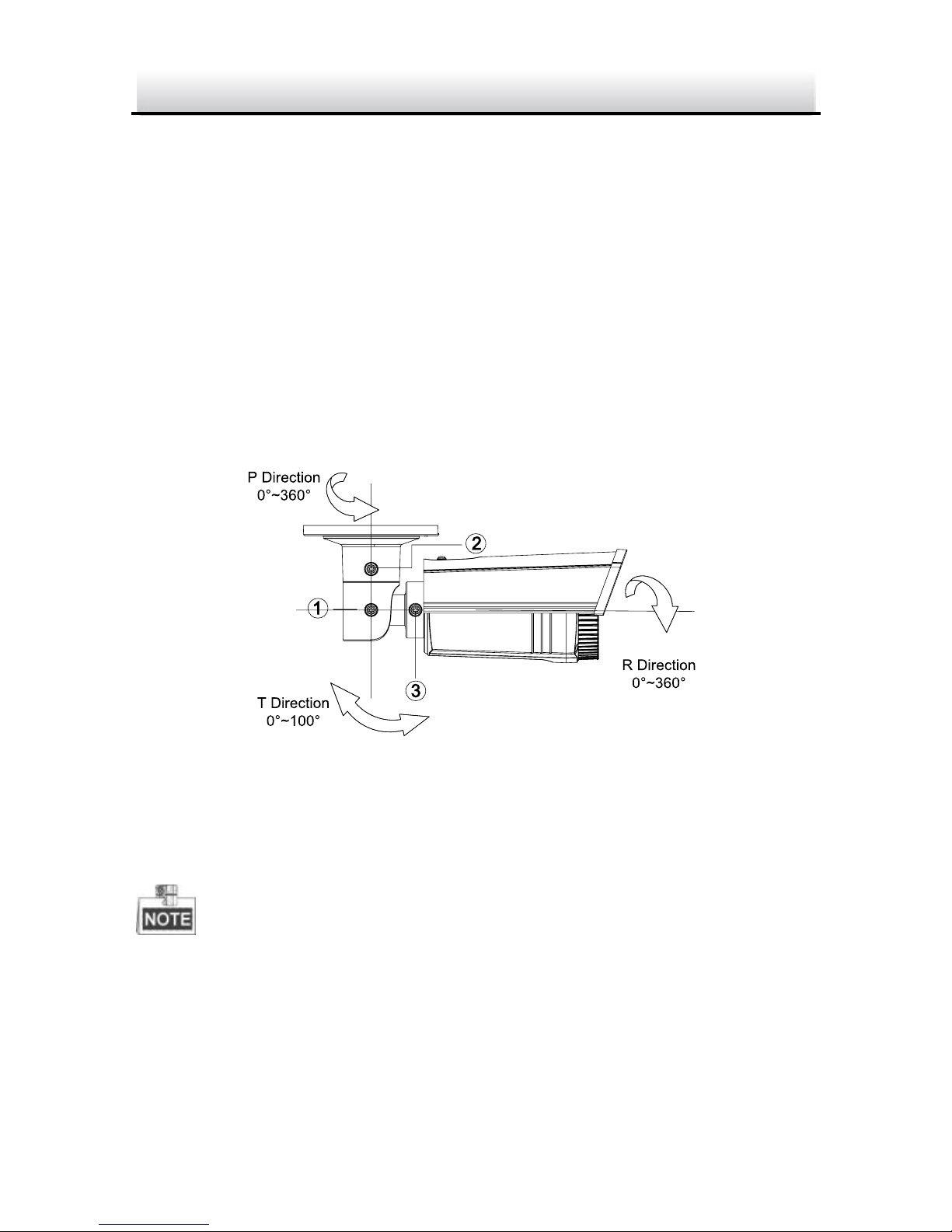
5. Adjust the Lens.
1). Loosen screw 1 to adjust the pan direction [0°~360°].
Tighten the screw after completing the adjustment.
2). Loosen screw 2 to adjust the tilt direction [0°~100°]. Tighten
the screw after completing the adjustment.
3). Loosen screw 3 and rotate the camera [0°~360°] to adjust
the lens to the surveillance angle. Tighten the screw after
completing the adjustment.
Figure 2-3 3-axis Adjustment
2.2 Installation of Type III HD-SDI IR Bullet Camera
Both wall mounting and ceiling mounting are suitable for type III
HD-SDI IR bullet camera. Ceiling mounting will be taken as an
example in the section. And you can take steps of ceiling mounting
as a reference if wall mounting is adopted.

HD-SDI IR Bullet Camera·User Manual
14
14
Steps:
1. Drill the screw holes in the ceiling according to the drill template.
Figure 2-4 Drill Template
2. Route the corresponding cables.
3. Secure the camera to the ceiling with the supplied PA4 Screws.
Figure 2-5 Secure the Camera to the Ceiling
4. Connect the corresponding power/HD-SDI/CVBS cables.
5. Adjust the Lens.
1). Loosen the adjustable nut.

HD-SDI IR Bullet Camera·User Manual
15
15
2). Adjust the pan direction [0°~360°].
3). Adjust the tilt direction [0°~90°].
4). Rotate the camera [0~360°] to adjust the lens to the
surveillance angle.
5). Tighten the adjustable nut to complete the installation.
Figure 2-6 3-axis Adjustment
This manual suits for next models
3
Table of contents


