LCO Technologies CROSSFIRE User manual

The CROSSFIRE
Ultra-low Power Chemical Injection Pump
Installation and Operations Manual
Version 5.1

CROSSFIRE Installation & Operations Manual
2 | Page
© 2017, LCO Technologies LTD. All rights reserved. (V5.1)
Table of Contents
CSA Requirements and Installation Requirements ................................................................................ 3
CROSSFIRE Installation Guide ............................................................................................................. 7
Optional Step: Connect the CROSSFIRE to a SCADA/RTU System................................................ 10
Optional Step: Wire in Motor soft stop switch ................................................................................... 10
CROSSFIRE Pump Start Up................................................................................................................ 13
Software Installation:............................................................................................................................ 14
Computer Interface Software............................................................................................................ 14
Wireless Option................................................................................................................................ 14
Interface Guide .................................................................................................................................... 15
Main menu ....................................................................................................................................... 16
Motor Control Tab ............................................................................................................................ 18
System Status Tab........................................................................................................................... 21
System Setup Tab............................................................................................................................ 22
System I/O Tab ................................................................................................................................ 24
Automation Tab................................................................................................................................ 25
Terminal Tab.................................................................................................................................... 29
Frequently Asked Questions: Automation & MODBUS..................................................................... 30
Possible Fault Codes ....................................................................................................................... 32
Controller Troubleshooting ............................................................................................................... 34
Connection Errors......................................................................................................................... 34
COM Port Issues .......................................................................................................................... 35
CROSSFIRE Maintenance................................................................................................................... 36
Fluid End Disassembly, Maintenance, and Re-Assembly................................................................. 37
Replace Fluid End............................................................................................................................ 37
Inspection......................................................................................................................................... 38
CROSSFIRE Pump Troubleshooting ................................................................................................... 42
CROSSFIRE Return and Repairs ........................................................................................................ 46

CROSSFIRE Installation & Operations Manual
3 | Page
© 2017, LCO Technologies LTD. All rights reserved. (V5.1)
CSA Requirements and Installation Requirements
IMPORTANT SAFETY CONSIDERATIONS
WARNING
AVERTISSEMENT
EXPLOSION HAZARD - SUBSTITUTION OF COMPONENTS
MAY IMPAIR SUITABILITY FOR INSTALLATION IN HAZARDOUS LOCATIONS
RISQUE D'EXPLOSION - LA SUBSTITUTION DE COMPOSANTS
PEUT RENDRE CE MATÉRIEL INACCEPTABLE POUR LES
EMPLACEMENTS DANS DES ENDROITS DANGEREUX (CLASSE 1, DIVISION 2).
WARNING
AVERTISSEMENT
EXPLOSION HAZARD - DO NOT REPLACE COMPONENTS
UNLESS POWER HAS BEEN SWITCHED OFF OR THE AREA IS
KNOWN TO BE NON-HAZARDOUS.
RISQUE D'EXPLOSION - COUPER LE COURANT OU
S'ASSURER QUE L'EMPLACEMENT EST DÉSIGNÉ NON
DANGEREUX AVANT DE REMPLACER DES COMPOSANTS.
WARNING
AVERTISSEMENT
EXPLOSION HAZARD - DO NOT CONNECT OR DISCONNECT EQUIPMENT
UNLESS POWER HAS BEEN SWITCHED OFF OR THE AREA IS
KNOWN TO BE NON-HAZARDOUS.
RISQUE D'EXPLOSION - AVANT DE DÉBRANCHER
L'ÉQUIPEMENT, COUPER LE COURANT OU S'ASSURER
QUEL'EMPLACEMENT EST DÉSIGNÉ NON DANGEREUX
WARNING
AVERTISSEMENT
THE CONTROLLER ASSEMBLY IS FOR USE IN CLASS I, DIVISION 2, GROUPS C AND D, AND OR
NONHAZARDOUS LOCATIONS ONLY.
L’APPAREIL DU CONTRÔLEUR CONVIENT À L’UTILISATION DANS LES EMPLACEMENTS
DE CLASSE 1, DIVISION 2, GROUPES C ET D, OU NE CONVIENT
QU’A L’UTILISATION DANS DES EMPLACEMENTS DÉSIGNÉS NON DANGEREUX.
WARNING
AVERTISSEMENT
THE MOTOR ASSEMBLY IS FOR USE IN CLASS I, DIVISION 1, GROUPS C AND D, AND OR
NONHAZARDOUS LOCATIONS ONLY.
L’APPAREIL DU MOTEUR CONVIENT À L’UTILISATION DANS LES EMPLACEMENTS
DE CLASSE 1, DIVISION 1, GROUPES C ET D, OU NE CONVIENT
QU’A L’UTILISATION DANS DES EMPLACEMENTS DÉSIGNÉS NON DANGEREUX.

CROSSFIRE Installation & Operations Manual
4 | Page
© 2017, LCO Technologies LTD. All rights reserved. (V5.1)
AGENCY
CERTIFICATION
Controller Assembly
(Must be placed in a Cabinet/Enclosure that provides a minimum Ingress Protection of NEMA
4/IP54)
Class 1, Division 2, Groups C and D, or nonhazardous.
Temperature Code: T4, Tamb: -40 – 60 Deg. C.
Suitable for Zone 2, IIB.
Motor Assembly
(Motor is for indoor or protected environment use only)1
Class 1, Division 1, Groups C and D, or nonhazardous.
Temperature Code: T6, Tamb: -40 – 60 Deg. C.
Suitable for Zone 1, IIB.
Models:
Explosion Proof Motor Assembly Model LCOM-1000
Controller Model LCOC-1000-A and Model LCOC-1000-B
IMPORTANT: Conditions of Certification
The Controller must be installed within an enclosure suitable for the environment and requiring a
tool or key to open. Controller Models LCOC-1000A and LCOC-1000B are intended for use in a
Pollution Degree 2 environment.
The RS232 connector must be retained with two screws on the mating connector.
The Ethernet RJ45 connector must be retained with its original locking tab to withstand a 15
Newton pull force once engaged.
Model LCOM-1000 must be used together to form a Certified Brushless DC (BLDC) Motor
System. No substitutions of Motor types are permitted.
Controller
The controller input voltage rating is: 24 VDC. The Battery power supply must be capable of supplying
24 VDC to ensure reliable operation and motor start-up. For average current draw based on
application, and help with solar sizing, please contact LCO directly. Average current draw on most
applications is significantly less than 1 A, however the rated maximum current draw for the controller is
9.6A.
The Controller must be protected by external over current protection in keeping with CEC and NEC
practices supplied at the time of installation.
EXTERNAL CONNECTORS
The controller features several external connectors. These are labelled as follows:
•Power In: connectors are used to connect the 24VDC power supply.
•To Motor: connectors are used for Phase A, Phase B and Phase C of BLDC. These connections
are not phase sensitive.
1Note: Protected environment means the motor must be under a shelter and off the ground to protect the motor
from moisture (such as rain, snow, ice etc.)

CROSSFIRE Installation & Operations Manual
5 | Page
© 2017, LCO Technologies LTD. All rights reserved. (V5.1)
Use only Copper Conductors on Supply and Motor Load Terminal Blocks
“TIGHTEN TO 10.54 pound-inches (1.2 N•m)”. Or Equivalent
It is a CSA requirement to use #10 straight or ring lugs with 10 AWG wiring, when connecting to the
Power and Motor connectors. The Controller data connectors can accept 20 to 24 AWG stranded wire.
All wiring and connections must be in line with accepted wiring practices as outlined by the Canadian
Electrical Code (Canada) and the National Electrical Code (USA) and installed by qualified personnel
only. (Use copper conductors only)
There are two patterns of mounting holes on the Controller unit. The four corner mounting positions are
for a direct fastening to the enclosure using # 6 screws. The two patterns of 3 holes are for DIN Rail
mounting brackets. Installer must supply screws and brackets as applicable.

CROSSFIRE Installation & Operations Manual
6 | Page
© 2017, LCO Technologies LTD. All rights reserved. (V5.1)
Motor
Accurate mechanical lineup is essential for successful operation. Mechanical vibration and roughness
in running the motor may be an indication of poor alignment. It is recommended that the lineup be
checked when installed.
For direct coupled applications, use flexible couplings when possible. Use of a sealed fitting at the
motor wiring entrance point is required with a minimum of 5 full thread engagement to maintain the
Class I, Division1 rating of the motor when installed in a Hazardous Area.
The three Phase conductors and the Earth ground must be terminated in an approved Class I, Division
1 junction box. The green Earth lead must be grounded to the ground screw in the junction box.
WARNING: Motor, Control and Grounding must be in accordance with the Canada -Canadian Electrical
Code and/or USA – National Electrical Code and consistent with Local requirements and practices. Use
Ground lug on exterior of Motor enclosure and Ground lead provided to ensure proper Grounding of the
Motor.
See below for Safe Operating Area Curves (SOAC) for the Motor
Figure: Safe Operating Area Curves (SOAC)

CROSSFIRE Installation & Operations Manual
7 | Page
© 2017, LCO Technologies LTD. All rights reserved. (V5.1)
CROSSFIRE Installation Guide
Step 1: Open Boxes
−Confirm the following parts are present
oLCOD-PUMP Box:
Assembled LCOD-Pump
Yoke covers
Mounting bracket
Additional accessories ordered
oLCOC-1000-A or LCOC-1000-B Box:
Controller (advanced or basic)
−Check to ensure no parts were damaged during shipment
oContact the shipment carrier and file a claim if any damage has been identified
oIf replacement parts are required, please contact your supplier
−Familiarize yourself with all parts and pieces
Step 2: Mount the pump
−Find a desired location for installation
oA location that can accommodate pump dimensions (22” L x 22” W x17” H)
oMinimize elevation to exploit head pressure created by the chemical tank. This will assist
in priming the inlet line.
−Mount the mounting bracket and LCOD-Pump within the bracket
oThe mounting bracket is designed to bolt down to the pattern of a 5100 series pump.
oBolt the two bracket pieces onto the existing 5100 pattern
oSet the CROSSFIRE pump on top of the bracket
oAttach the four-foot bolts to the base flange on the motor enclosure
Note: The bracket can be drilled to accommodate other bolt pattern configurations. Alternatively, the
pump can be free standing on the bracket; it can be attached to the bracket but not bolted down in a
drip tray if preferred.

CROSSFIRE Installation & Operations Manual
8 | Page
© 2017, LCO Technologies LTD. All rights reserved. (V5.1)
Step 3: Install the Smart Controller
−Mount the Controller in a Nema 4 Enclosure
−Hook the controller to a 24 VDC power supply
oConnect the 2 conductor, 10 gauge tech cables with appropriate environmental and
classification seals to the controller
−Attach the three conductor cables from the motor to the controller. The green ground wire can
be terminated at any ground. The conductor cables must be terminated in a Class 1, Division 1
junction box at the motor.
oThe three conductor cables will be terminated in the controller at termination points
marked phase A, phase B, and phase C. Although the wires are not required to be in a
particular order for the pump to function, to maintain consistency please attach the red
wire to PH A, the black wire to PH B, and the yellow wire to PH C.
oCables are gauge 10 and can be a maximum length of 60 ft
Warning: If the resistance in the gauge 10 wires does not meet AWG standards, the
distance must be reduced proportionately.
Note: All conductor cables must be attached with proper end ferrule connectors and clamped down
properly with the appropriate tools. Ensure installers double check that all screw terminals are tightened
down to avoid any electrical connection issues. Similarly, if two wires must be spliced together, please
use a proper splicer connector, clamp down sufficiently, and do not use electrician twist caps.
Note: Wiring instructions are per device. Multiple CROSSFIRE units cannot be wired off
a single cable run. Any deviation can affect CROSSFIRE performance. Please consult
LCO Technologies directly for assistance prior to deviation if required.

CROSSFIRE Installation & Operations Manual
9 | Page
© 2017, LCO Technologies LTD. All rights reserved. (V5.1)
Step 4: Check Fluid Ends
−Ensure that the fluid ends are showing 6-7 threads
oIf 6-7 threads are not showing, the plunger may bottom out and cause the pump
to stall or draw higher than average current (details in troubleshooting)
−Check that the packing gland is snug but not over tightened
Step 5: Manual Rotation Check
−Complete a manual rotation fluid end check
−Remove the clear acrylic top cover from the pump
−Insert an Allen key into the bolt in the center motor shaft and manually spin the motor
oIf the fluid ends are installed correctly, the motor will spin all 360 degrees with no
resistance
oIf there is resistance that cannot be pushed past, a fluid end is bottoming out on the
plunger
oManually spin that fluid end out of the yoke, one turn at a time, until you can push past
the fluid end to the next one
oRe-check and complete a full 360-degree rotation
−For more information, and a visual representation of the manual rotation, please visit
www.lcotechnologies.com/resources.html and watch the YouTube Video called “Video Tutorial
Manual Fluid End Check” or call LCO directly for more assistance
Warning: If the fluid ends are bottoming out, this will cause damage to the pump
components and may lead to extreme wear and tear. Damage will not be covered by
warranty and chemical leaks may occur due to misalignment.
Step 6: Tube Fluid Ends
−The fluid ends on the CROSSFIRE are a 5100 series equivalent
−The fluid ends have a ¼” Female NPT connection on the inlet and outlet
oThe arrow on the side of the fluid end body indicates fluid flow direction
−Tube the fluid ends inlets and outlets appropriately
−Overpressure protection must be used in conjunction with our pump
oWe recommend using a Panam Relief Valve (PRV-04-SS) with a set pressure
established which is no greater than the maximum allowable working pressure (MAWP)
of the system.
oOnly one relief valve is required if all fluid ends are going to a single injection point.

CROSSFIRE Installation & Operations Manual
10 | Page
© 2017, LCO Technologies LTD. All rights reserved. (V5.1)
−Recommendation: Use a filter on the pump inlet, this ensures that no foreign matter particles
get into the fluid ends during chemical injection.
Optional Step: Connect the CROSSFIRE to a SCADA/RTU System
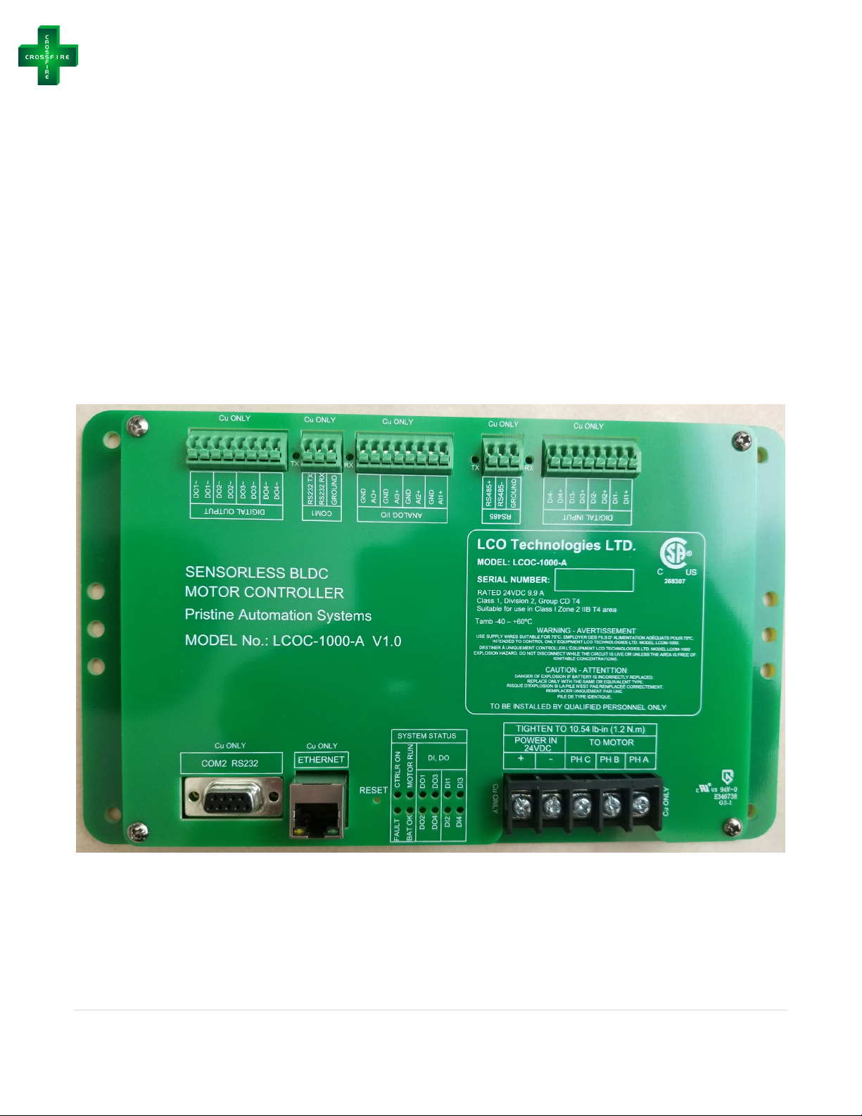
−Connect three 20 Gauge wires to the RS485 terminal blocks on the CROSSFIRE controller.
oRS485+, RS485-, and RS 485 GROUND
−Connect the wires to the SCADA/RTU system
−Install a two-position selector switch on the outside of the NEMA 4 enclosure to ensure
when an Operator is onsite completing maintenance, that the pump can be manually
switched from remote control mode, into local control mode for safety. This switch is
required for safety purposes; all MODBUS registers can be monitored remotely when the
switch is on remote control mode.
oWire the switch to the Digital Input DI1 terminal block on the controller such that 24 VDC
will be on DI1+ when remote position is selected and 0 VDC for the local positioner
−Download and connect to the CROSSFIRE computer software as per the download and
operations instructions on page 14
oLog in as “Technician” for access to all tabs
oGo to “System Setup” panel (picture on page 22)
Set your Slave ID and Baud Rate
Press “Save” button
oGo to “Automation” Tab (picture on page 28)
Select “local remote switch control” from the drop-down menu to enable the two-
position selector switch
Press “Save” button
Label position one and two on the outside of the panel to “local” and “remote”
For all MODBUS register maps and assistance to set up MODBUS, please contact your local
distributor or LCO Technologies directly
Optional Step: Wire in Motor soft stop switch (non-positive isolation feature)
−If connecting over MODBUS, a C1D2 two-positioner switch may be wired to the controller for a
local “Start/Stop” motor switch. This switch will allow Operators onsite to turn the motor ON or
OFF with an easy switch (no laptop or Bluetooth connection App required) but will not prevent
MODBUS users to view pump parameters remotely as the power to the controller has not been
affected.
−Note: This is not a positive isolation method of stopping the motor, consider this equivalent to
the “start/stop” buttons in the app and laptop software
−Wire the C1D2 two-positioner switch according to the diagram below (next page, page 11):
oApply 24 V to AI3+ and 0 V to Ground
oLabel the switch ON for 24V, and OFF for 0V
−Access the “Terminal Tab” in the software or mobile App and enter command
“setMotorSoftStopEn” to enable function
−Confirm function by entering command “showMotorSoftStopEn”

CROSSFIRE Installation & Operations Manual
11 | Page
© 2017, LCO Technologies LTD. All rights reserved. (V5.1)
Figure: Wiring Diagram for Soft Stop Switch on AI3+
Note: Please use Gauge 20, single strand wires for all signal terminals on the smart
controller.

CROSSFIRE Installation & Operations Manual
12 | Page
© 2017, LCO Technologies LTD. All rights reserved. (V5.1)
Installation Requirements – Summary Diagram:
Note: Wiring instructions are per device. Multiple CROSSFIRE units cannot be wired off
a single cable run. Any deviation from the above diagram can affect CROSSFIRE
performance. Please consult LCO Technologies directly for assistance prior to
deviation if required.
Solar Panels (PV Panels)
or Thermal Generator
CROSSFIRE Pump or Compressor
Wires from PV Panels to Charger
Max Length: 80 ft
Wire Gauge: AWG 10
Solar Charger
Battery Box
CROSSFIRE Controller
LCOC-1000-A/B
24 VDC: Charger to Batteries
Max Length: 60 ft
Wire Gauge: AWG 10
24 VDC: Charger to Controller
Max Length: 60 ft
Wire Gauge: AWG 10
3 Phase Motor Leads
Controller to Pump/Compressor
Max Length: 60 ft
Wire Gauge: AWG 10

CROSSFIRE Installation & Operations Manual
13 | Page
© 2017, LCO Technologies LTD. All rights reserved. (V5.1)
CROSSFIRE Pump Start Up
Step 1: Prime the Fluid Ends
−Once fluid ends are tubed, install a 1/8” NPT x 1/4” or 3/8” compression fitting into the threaded
outlet of the priming valve. Tube this fitting and use it to capture vented chemical that flows
during the priming process.
−Open the priming valve and let the chemical run through the fluid end until you have a steady
flow of chemical with no air bubbles to ensure no vapour is present in the system.
−Close the priming valve
Note: If the pump does not deliver the chemical during this priming process as expected, flood the
discharge line with a hand pump connected to the threaded vent of the priming valve. Generally, this
step is not required when using ½” or 3/8” fluid ends, however when using 3/16” or 1/4” fluid ends,
particularly under high pressures; this may necessary.
Optional Step: Priming with Hand Pump
−Connect the hand pump to the threaded vent on the priming valve
−Open the priming valve
−Push chemical through with the hand pump to completely flood the discharge line
Step 2: Start the pump
−Connect an RS 232 cable to the controller and computer
oAlternative: connect an LCO Bluetooth dongle for wireless communication
−Start up the chemical injection pump as per the operator interface instructions starting on page
15.
Warning: Pinch Hazard
Always keep the clear acrylic top plate on the unit while the pump is running
Step 3: Gauge the Pump
−After setup and installation is complete, run the pump and gauge chemical volume delivery rate
oRecommended steps:
Install a calibrated sight glass
Fill the sight glass (the sight glass will fill to match the level in the chemical tank)
Isolate the tank
oOpen the isolation valve on the base of the sight glass
oClose the isolation valve on the chemical tank
oRun the pump, observe and adjust the chemical delivery rate as required
−Check for leaks from packing glands and tubing
oIf there are leaks from the packing gland, refer to page 42

CROSSFIRE Installation & Operations Manual
14 | Page
© 2017, LCO Technologies LTD. All rights reserved. (V5.1)
Software Installation:
Step 1: Download the Computer Interface Software
−Go to https://lcotechnologies.com/resources.html
−Click on download button and follow all prompted instructions
−ZIP file password: crossfire2017
−The Interface is compatible with the following operating systems:
oWindows 7
oWindows 8.1
oWindows 10
−Both the operator and technician tabs are password protected.
oOperator Password: Pristine
oTechnician Password: Automatio
Wireless Option:
−In addition to the full computer software, there is a wireless communication option to the
computer software or to a mobile phone or tablet
−Required Parts:
oBT-SAI-01 (BT5-SAI) or BT-PTM-01 (BT5-PTM)
oOptional: BT-USB-01 (BT5-USB) for laptop connection
only
−Download mobile App on Apple App Store or Android App
Store
oSearch “CROSSFIRE” or “LCO CROSSFIRE”
oAlternative: go to the LCO website and click on the App
store link listed under the “Resources” tab
−Both the operator and technician tabs are password protected
oOperator Password: Pristine
oTechnician Password: Automatio
−If using BT-SAI-01 with a laptop for wireless connection, go to
https://lcotechnologies.com/resources.html and download the
device driver (Drivers for USB->Bluetooth adapter)
oNo password required
−For any other information regarding wireless Bluetooth
communication and installation details, please refer to the
Bluetooth Product Spec Sheet found at: https://lcotechnologies.com/resources.html

CROSSFIRE Installation & Operations Manual
15 | Page
© 2017, LCO Technologies LTD. All rights reserved. (V5.1)
Interface Guide
The LCO Technologies CROSSFIRE Configuration Software is a tool used to easily monitor and
configure the controller that drives the CROSSFIRE pump with a RS232 serial connection.
Additionally, a mobile version of the software for cell phones and tablets is available using Bluetooth
Low Energy communications.
There are two distinct logins for the interface – technician and operator. Operators have viewing access
to all tabs, however, can only make changes within the motor control and system status panels.
Technicians have access to all panels and can make changes to all settings, including the more
advanced automation features in the automation tab.
Interface Overview
The CROSSFIRE configuration software is divided into three regions:
Figure: CROSSFIRE Configuration Software main window
1) Main menu bar: Used to connect and disconnect from the CROSSFIRE controller and switch
between operation tabs.
2) Motor control panel: Shows motor status and is used to start/stop the motor and set motor
speed (available for both operators and technicians). Additionally, will display advanced
automation mode instead of speed settings if configured.
3) Configuration panel: Used to view and edit the configuration data stored on the CROSSFIRE
controller (ex. plunger size, and chemical injected)
1
2
3
1
2
1
3

CROSSFIRE Installation & Operations Manual
16 | Page
© 2017, LCO Technologies LTD. All rights reserved. (V5.1)
Main menu
Connect to Controller:
The main screen is used to scan for devices and connect to the CROSSFIRE controller and pump.
Ensure the pump is powered on and click Scan for Devices and select the appropriate COM Port.
−See: Troubleshooting – COM Port Issues if needed
Log into the Controller:
1) Login as: Select operator, or technician. Operators only have access to change basic settings;
Technicians have access to change all settings, including advanced configuration options.
2) Password: Enter the correct password to log in to the controller as operator or technician.
oOperator Password: Pristine
oTechnician Password: Automatio
Figure: Computer Interface Main Page – Connecting to a CROSSFIRE Controller
Figure: Computer Interface Main Page – Log in as Operator or Technician
Figure: Mobile App Login

CROSSFIRE Installation & Operations Manual
17 | Page
© 2017, LCO Technologies LTD. All rights reserved. (V5.1)
If connecting to the controller succeeds, the configuration and status panels will be enabled and will
begin showing data from the pump. If the attempt to connect fails, an error message will be displayed
(see: Troubleshooting – Connection Errors).
Figure: Computer Interface Main Page – Log in as Operator or Technician
Figure: Mobile App Login
Figure: Computer Interface Main Page – Successful Login

CROSSFIRE Installation & Operations Manual
18 | Page
© 2017, LCO Technologies LTD. All rights reserved. (V5.1)
Disconnect from Controller:
To disconnect from the controller, click the white X in the top right-hand corner.
Motor Control Tab
Figure: Motor Control Tab – Pump Setup
The Motor control tab is used to specify the physical setup and operational speed of the CROSSFIRE
platform, and is divided into two regions:
1) Fluid end settings, to record configuration of the pump
2) Save/reload buttons, to transfer the configuration to and from the CROSSFIRE controller.
Note: Fluid end settings are only visible when configured as a pump and hidden when configured as a
compressor.

CROSSFIRE Installation & Operations Manual
19 | Page
© 2017, LCO Technologies LTD. All rights reserved. (V5.1)
The fluid end settings are used to configure the four fluid ends that can be installed on the CROSSFIRE
platform. Each fluid end has a separate setup pane:
The chemical code dropdown menu is used to indicate whether a fluid end is installed on each of the
four available positions on the CROSSFIRE platform and to indicate chemical type. Enabling or
disabling the fluid end allows the controller to correctly track the total accumulated number of pump
strokes the system has made per motor rotation; thus, it is critical to ensure if a fluid end is not
present, disable is selected and saved.
Fluid end plunger size and stroke length is also recorded here and based on those parameters in
addition to speed of the pump, an estimated delivery rate will be displayed. The standard gearbox
installed on the CROSSFIRE platform allows the system to be run between 1 and 45 RPM. Stroke
length by standard is 1”, however can range from between 0.35”-1.00” when an adjustable stroke
length plunger is installed.
Note: The volume injected is a theoretical calculation based on operation parameters, and actual
volume delivered may vary from this depending on factors such as system pressure and packing
materials used in the fluid end.
Figure: Motor Control Tab - Pump setup

CROSSFIRE Installation & Operations Manual
20 | Page
© 2017, LCO Technologies LTD. All rights reserved. (V5.1)
Figure: Save/Reload buttons
The Save button saves any changes made to the fluid end settings and pump speed to the
configuration data saved in the controller.
The Reload button reloads the saved configuration data from the controller.
Note: Any unsaved changes made to the settings will be lost.
Motor Control Panel
The motor status panel is used to configure and check the status of the system drive motor:
Figure: Motor control panel
When connected to the controller, the start/stop button will start or stop the motor when the controller is
connected and online. The motor speed selection configures the RPM setpoint of the motor and can be
changed from the drop-down menu or the up and down arrow buttons.
Note: This panel will change based on the automation mode configured. If the chemical pump is
configured in proportional control mode for example, the motor status will reflect the active
configuration.
Other manuals for CROSSFIRE
1
Table of contents
Popular Water Pump manuals by other brands

Zoeller
Zoeller 023072 owner's manual

Graco
Graco Dura-Flo 900 Instructions-parts list

CHERNE
CHERNE AQUA-LOC 278-138 Operation and maintenance manual

ITT
ITT Goulds Pumps 3107 Installation, operation and maintenance instructions

Graco
Graco President 24H627 Instructions-parts list

Xylem
Xylem GOULDS AC8743 instruction manual

Pentair
Pentair JUNG PUMPEN MultiStream UAK Series instruction manual

Ingersoll-Rand
Ingersoll-Rand ARO PP10A A Series Operator's manual

Liberty Pumps
Liberty Pumps HT40 Series installation manual

KNF
KNF NF 1.300 EX Operating and installation instructions

Bayrol
Bayrol Automatic Cl/pH quick guide

sauermann
sauermann OMEGA PACK Si-20 manual