LCPRO SHARKi User manual

SHARKi
IP66 BEAM Movinglight
User Manual
V1.1

Table of contents
1. SAFETY INSTRUCTIONS..........................................................................................................................................1
2. PRODUCT INTRODUCTIONS...................................................................................................................................3
2.1 DIMENSIONS .............................................................................................................................................................3
2.2 FIXTURE OVERVIEW .................................................................................................................................................4
2.3 ACCESSORIES ...........................................................................................................................................................4
3. PACKING AND SHIPPING.........................................................................................................................................5
3.1 PROTECTION LOCK.............................................................................................................................................5
3.2 UNPACKING ..........................................................................................................................................................5
3.3 PACKING AFTER USE ................................................................................................................................................5
4. INSTALLATION ................................................................................................................................................................6
4.1 CLAMPS INSTALLATION ...................................................................................................................................6
4.2 DEVICE INSTALLATION .....................................................................................................................................6
4.3 LAMP FITTING AND ADJUSTMENT ............................................................................................................................7
5. POWER / CONTROL CONNECTION .................................................................................................................................8
5.1 POWER CONNECTION ................................................................................................................................................8
5.2 CONTROL CONNECTION...................................................................................................................................8
5.3 TESTING.................................................................................................................................................................8
6. CONTROL PANEL ............................................................................................................................................................9
6.1 PANEL INSTRUCTION ................................................................................................................................................9
7. TECHNICAL SPECIFICATION ..........................................................................................................................................10
8. GOBOS AND COLORS.............................................................................................................................................12
8.1 GOBOS..................................................................................................................................................................12
8.2 COLORS................................................................................................................................................................12
9. MENU STRUCTURE .................................................................................................................................................13
10. DMX PROTOCOL ....................................................................................................................................................16
11. SYSTEM WIRING DIAGRAM ...............................................................................................................................18
12. MAINTENANCE AND TROUBLESHOOTING....................................................................................................19
12.1 CLEANING AND MAINTENANCE.................................................................................................................19
12.2 TROUBLESHOOTING......................................................................................................................................19

1
1.Safetyinstructions
Beforeusingthefixture,readthelatestversionoftheproductusermanual,payingparticularattentionto
thesafetyinstructions.
m
ta
tc
The manufacture of this fixture, are not responsible for damages, resulting from misuse of this
fixture,duetothedisregardoftheinformationprintedinthisusermanual.
DANGER!
Hazardousvoltage.Riskoflethalorsevereelectricshock
WARNING!
Wearprotectiveeyewear.Neverlookdirectlyintothelightsource.
WARNING!
Burnhazard.Hotsurface.Donottouch.
Onlytodirectmountingonnon-combustiblesurfaces.
Minimumdistancetolightedobjects.
Replaceallcrackedglassshields.
Maximumambienttemperature.
Maximumtempoftheexternalsurface.

2
General guidelines
lThis product has a protection rating of IP66.
lNever open this fixture while in use.
lThe fixture should be kept clean. DO NOT operate the fixture in extreme heat or dusty environments. Avoid contact
with chemical liquid.
lMinimum distance to lighted objects must be 49.21feet (15m).
lMaximum temp of the external surface 194˚F (90˚C).
lMaximum ambient temperature 113˚F (45˚C).
lMinimum distance of inflammable materials from the surface 1.6 feet (0.5m).
lLamp should be changed if damaged or distorted in shape due to extreme heat.
lCover, prism or LCD Menu Function Display with visible damages such as cracks or scratches must be replaced to
ensure performance of the fixture.
lDisconnect the fixture from power before changing any parts or accessories.
lBasic insulation should be maintained between the controllable device and the product power supply.
lMake sure that the installation area can hold a minimum point load of 10 times the weight of all installed
fixtures, clamps, cables, auxiliary equipment, etc. Check that the cover, clamps and locks are undamaged. Certified
safety cables must always be used when installing the fixture.
lThe fixture is only intended for installation, operation and maintenance by qualified professional. Instructions stated in
the manual must be complied.
lThe fixture must be kept in a well-ventilated place at least 50 cm away from any wall surface. Check if the fans or
ventilation openings are unblocked.
lThis fixture uses discharge lamp. To avoid reducing the lamp’s life, wait at least 15 minutes after powering off to allow
the unit to cool down before handling.
lBroken or damaged cables and light source can only be fixed or changed by certified technicians, certified local
distributors or the manufacturer to ensure operational safety.
lDo not stick filters or other materials onto the lens. Do not modify the fixture or install other manufactured parts.
3
2. Production instructions
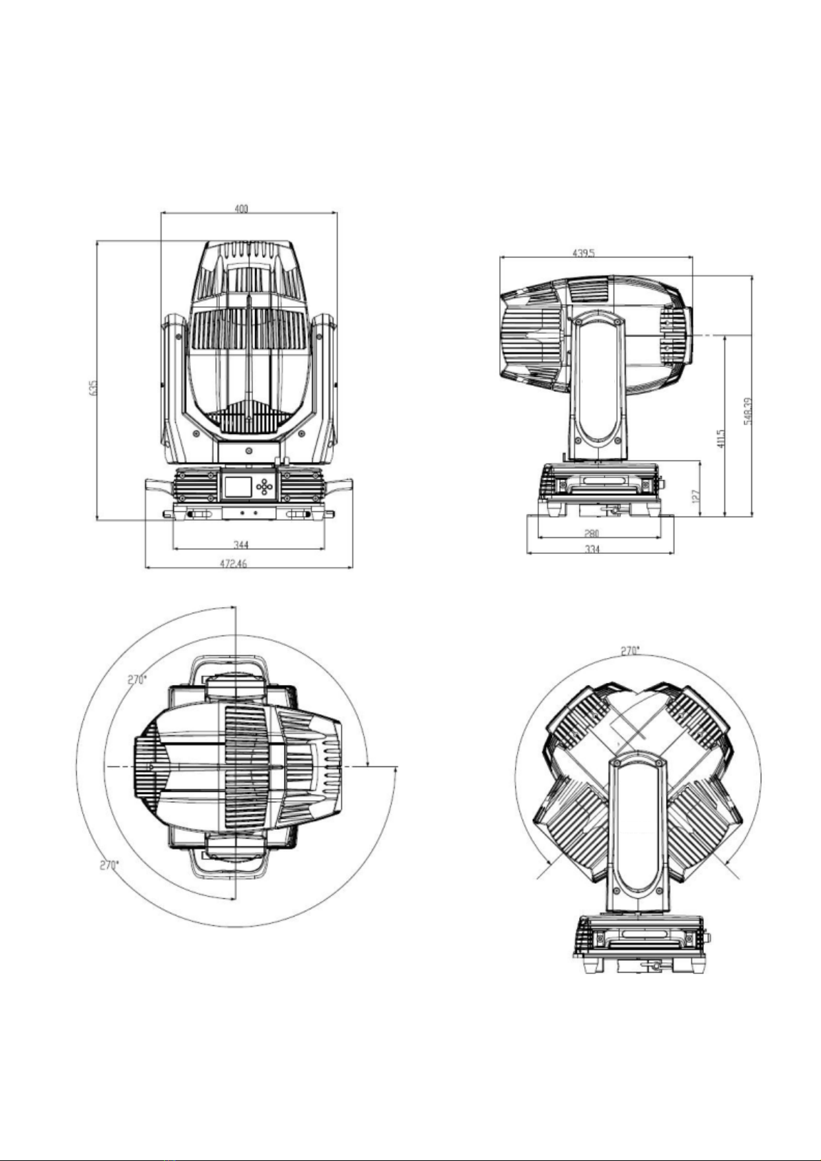
2.1 Dimensions

4
2.2 Fixture overview
2.3 Accessories
Item Qty Unit Remark
User Manual 1 Pc --
Clamps 2 Set Hanging integrated folding lamp, Load weight 200KG
Safety cable 1 Pc Φ5*60cm 7*19 pc with hook Material:Steel
5-pins signal line 1 Set --
Power cable 1 Set 1.5*2.5mm2

5
3. Packing and shipping
3.1 Protection lock
Pan and tilt locks are equipped to ensure safe transportation.
PAN: 4 lock positions are located evenly on the Pan.
3.2 Unpacking
Notes
All products are quality controlled and checked for any faults before they are dispatched to customers. If the fixture is
damaged during delivery, the customer must notify the shipper and manufacturer to file a damage insurance claim.
Photographic evidence of the damage must be provided.
Flight-Case:Open the cover of the flight-case and remove the plastic packing bags. Hold the handles of the fixture firmly
and take it out carefully.
Cardboard box:Open the box and take out the whole set of packaging foam which contains both the fixture and its
accessories. Remove the foam from the top, put away the accessories, and then take out the fixture wrapped in the plastic
bag.
Notes
Check if the pan and tilt are unlocked before connecting the fixture to power.
3.3 Packing after use
1. Switch off the fixture and wait for at least 5 minutes before disconnecting it from AC power. Cool down the fixture for
at least 15 minutes before packing.
2. Lock pan and tilt.
3. Flight case: Wrap the fixture in plastic bags. Hold it by the handles, and then carefully place it inside the flight case
along with all the accessories. Close the cover. Only 3 layers are allowed when piling up the flight cases. Do not upside
down.
4. Cardboard box: Wrap the fixture in plastic bags. Put it in the packaging foam along with all the accessories. Place the
other set of packaging foam on top then carefully put it inside the cardboard box.
水平保
护锁
P a n l o c k

6
4. Installation
4.1 Clamps installation
The fixture can be placed on the stage or mounted on the truss facing any direction. Attach the clamps to the mounting
position on the base of the fixture.
Warning:Use two clamps when mounting the fixture. Turn the screws attached to each clamp a 1/4 turn clockwise to lock.
Always remember to use the safety cable which goes through the mounting hole on the base. Do not attach the safety cable
on the handle.
4.2 Device installation
1. Make sure there is no damage on the clamps or safety cables before installation.
2. The clamp is mounted on the chassis of the fixture. Horizontally insert the clamp into the mounting holes of the chassis.
Fasten the clamp tightly by a 1/4 turn clockwise. Fix another clamp in the same way.
3. Check if pan is unlocked before connecting the unit to AC power.

7
4.3 Lamp fitting and adjustment
1. Disconnect the fixture from AC power. Cool down the fixture. Set the Tilt lock in a horizontal position.
2. Remove the lamp holder lower cover and plug out the waterproof terminal when disassemble the bulb, then loosen the
fixed plate and take out the bulb.
3. Put the bulb into the fixed plate, then press the bulb clockwise with the fixed plate when install the bulb, observe the bulb
spot and adjust it after lighted the bulb. Finally, plug in the waterproof fan and lamp holder lower cover.
Note
The fixture is equipped with PHILIPS MSD Platinum Flex 300S, which is featured with high efficiency and short-arc
characteristic, such as a stable 7200K color-temperature and average lifespan of 6000h.
Note
1. Fitting another type of lamp will cause potential damage to the fixture. Change the lamp before it reaches its lifespan.
Read the guidelines in the package carefully when fixing the lamp.
2. To avoid any impact on the beam, do not touch the bulb with your bare hands. The lamp must be kept clean with the use
of the clean paper contained in its package
Push the light bulb to the
hole,press it down
Enlarged
Remove the back
Back cover
Back cover
cc
8
5. Power/ Control connection
5.1 Power connection
Connection method:
ŸL (Live) Brown wire
ŸE (Earth) Yellow / Green bi-color wire
ŸN (Neutral) Blue wire
ŸThe voltage and frequency of the power source must be in compliance with the ones marked on the fixture. It is
strongly recommended that each fixture are to be connected to the power source separately so that they can be
switched on / off individually.
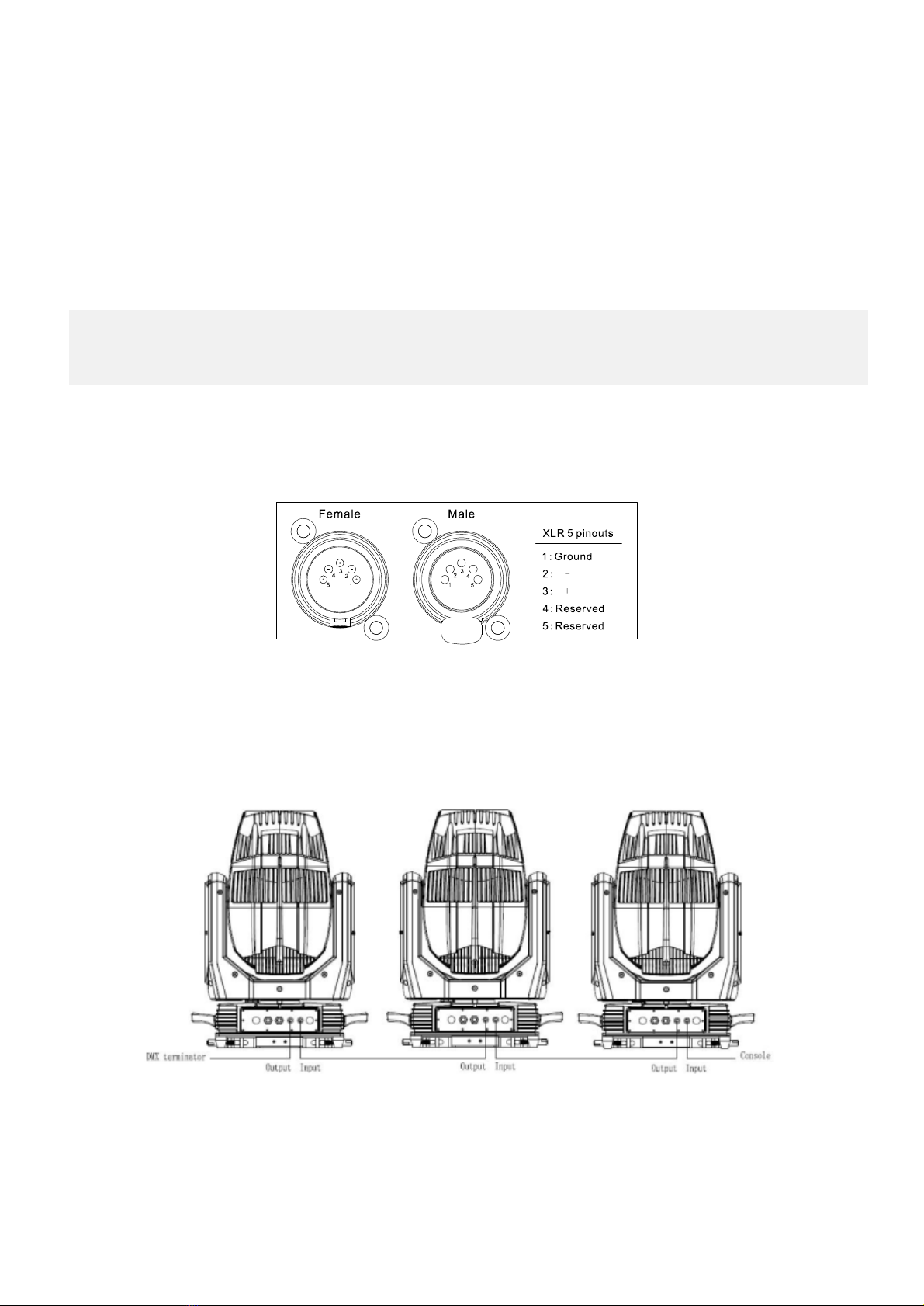
5.2 Control connection
The fixture has 5-pin XLR connectors for DMX data input and output as shown below. Connection between the console and
fixture, and between fixtures must be made with 2 core screened DMX signal cable. Maximum connecting distance of
signal cable is 150 meters. Additional DMX512 signal-amplifier is recommended for longer distance
Connect the Console’s DMX OUTPUT to the first fixture’s DMX INPUT, then the first fixture’s DMX OUTPUT to
the second fixture’s DMX INPUT and so on. It is recommended not to connect more than 32 units on a single
DMX universe. On the last fixture’s output connect a DMX terminator. (The terminator is a 5-pin XLR connector
with a 1/4W and 120Ωresistor between the pin 2 and pin 3) as shown below:
5.3 Testing
Connect the fixture to AC power. Check if the lamp is on and the fixture is independently controllable before
putting into operation.
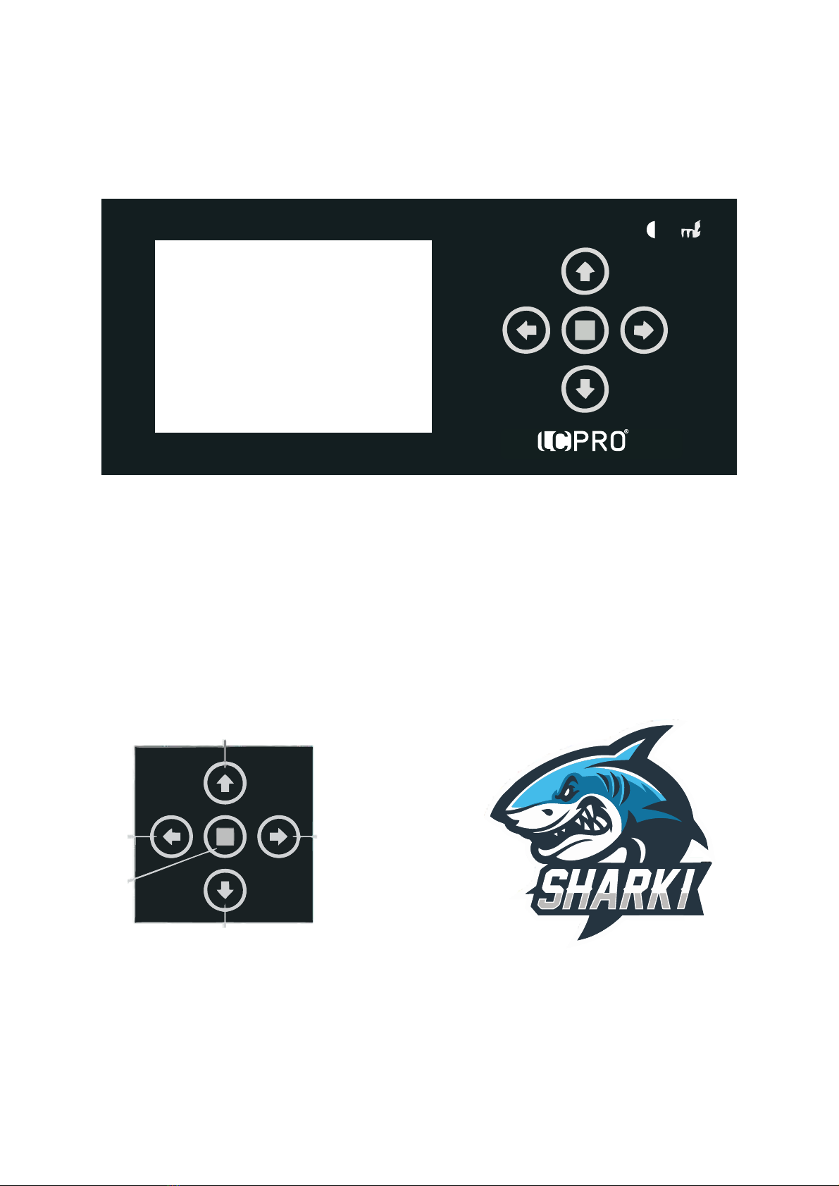
The control panel features touch-sensitive buttons and LCD digital display for quick and easy setup of address code
and functions menu.
Press UP or DOWN to view or select the function menu.
Press CNTER to choose a function and enter into corresponding sub menu. Each menu represents a specific function
of the fixture.
Press RIGHT to select the specific function and save the changes or enter into the submenu, then press UP or DOWN
to change the value of the selected function (increase or decrease).
Press RIGHT to return to the previous menu or exit.
Button panel indicator:
9
6.Controlpanel Panelinstruction
6.1
Upper
Left Right
Middle
Lower

10
7. Technical specification
lOptical
Light source: PHILIPS MSD Platinum Flex 300S
Expected average lifetime: 6000 h
Color temperature correction: 7200K
Zoom: 2°
CRI:Ra≥80
Focus: High-precision glass lenses, electronic linear HD focus
Prism: 1 pc tip 8-facet prism,1 pc tip 16-facet prism, prims can be controlled independently ,
or can be combined to make abundant beam effects
Frost: 1-independent frost effect
lGobo
Fixed gobo wheel: 12 gobos + open,CW/CCW rotation, variable speed
lColor
Color wheel: 14 colors + open, split color, CW/CCW rotation, “Rainbow effect” in both directions
lElectrical
Power input, nominal: AC 100-240V 50/60Hz
Max. Power consumption: 580W, max current: 2.9A, PF: 0.99
Power supply unit: Auto-ranging electronic SMPS
Main fuse: 250V/6.3A
Ballast: Electronic
Power input: Self-contained power cord
DMX data input/output: Chassis 5-pin (in/out)
lControl and programming
Control channels (DMX): 15/12/16
Protocol: DMX-512 RDM
Display: LCD
lPhysical / Installation
Weight: 24Kg (52.9lbs.)
IP rating: IP66
Material: Aluminum, steel, plastic
Mounting points: Four quarter-turn locking points + attachment points for safety wire
lDynamic effects
Pan/Tilt movement: 540˚/270˚
Iris: Motorized adjustable iris, wide range of variable pulse effects
Strobe: 1-20Hz, synchronized, pulse effects
11
Dimmer: 0-100%, mechanical dimming
lThermal
Operating range: 5˚F to 113˚F (-15˚C to +45˚C)
Startup range: -13˚F to 113˚F (-25˚C to +45˚C)
Storage range: -40˚F to 140˚F (-40˚C to +60˚C)
Cooling: Active fan
lCertification and Safety
EMC: EN 55103-1:2009, EN 55103-2:2009, EN 61000-3-2:2006+A2:2009, EN 61000-3-3:2013,
GB/T 17743-2007, GB 17625.1-2012
Safety: EN 60598-2-17:1989/A2:1991, GB 7000.1-2015, GB 7000.217-2008
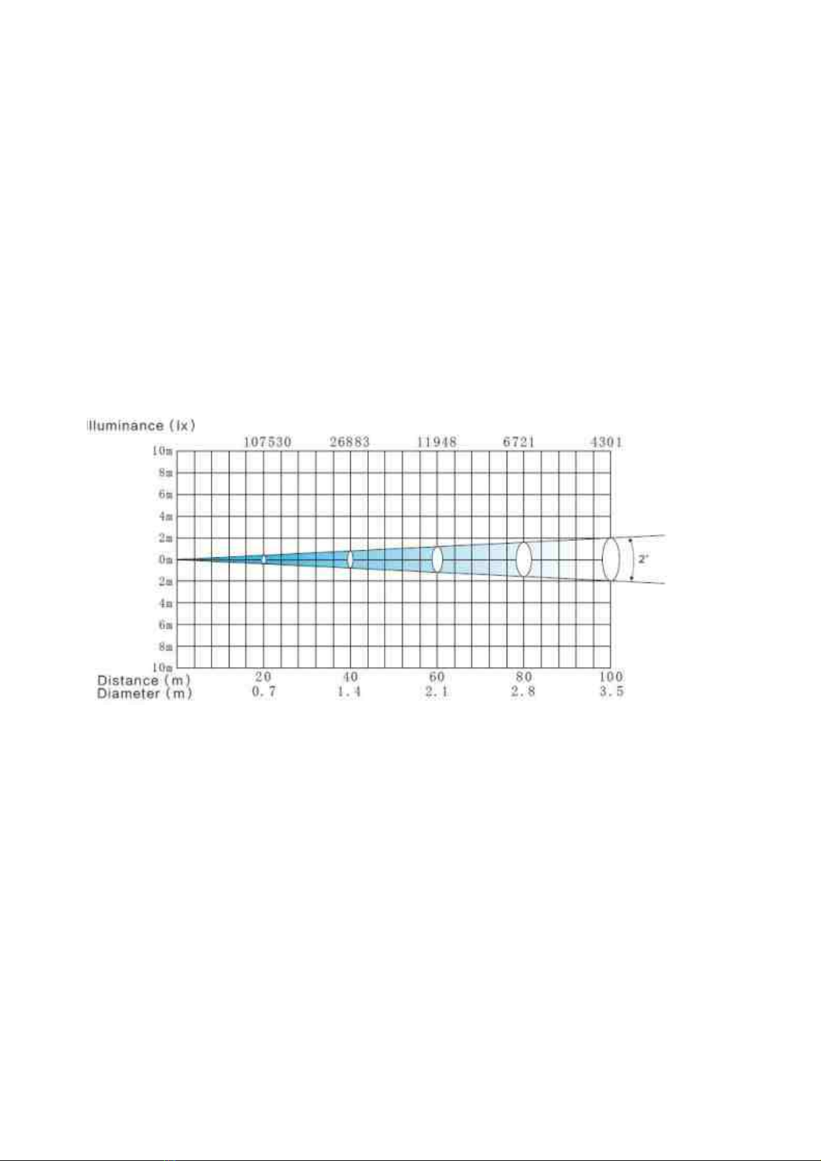
lPhotometric
lOther features
ØEnhanced stability of the fixture due to the wide input voltage AC/DC switching power supply which both reduces the
impact of power and voltage fluctuations, and removes the restriction of voltage and frequency variations in different
countries.
ØAutomatic energy saving: when the shutter or CMY is closed, power consumption will be reduced automatically with
the photoelectric tracking induction technology.
ØSleep mode: uses the most advanced technology to remotely activate sleep mode. When the fixture is disconnected
from signal, the sleep mode is enabled automatically to make it more stable and safer. Sleep time can be customized.
ØPower setting: built-in continuous rechargeable battery, allowing setting functional data via LCD interface without
power connection

12
8.Gobosandcolors
8.1Gobos
Onefixedgobowheel:12gobos+open,CW/CCWrotation,variablespeed
Fixedgobowheel
8.2Colors
Colorwheel:14colors+open,splitcolor,CW/CCWrotation,“Rainboweffect”inbothdirection
1.Red 2.Yellow 3.Blue 4.Yellow
green
5.Purplishred 6.Lightyellow
7.Bluegreen 8.Green 9.Rosered 10.Lavender 11.Fluorescence 12.Claybank
13.Brown 14.Coolwhite

13
9. Menu structure
Level
1Level 2 Level 3 Level 4 Info
1.Run
setting
1.Address Setting
2.Value Display
3.Auto-Program
Address: 001~ XXX
Pan ……,All,Off
Master /Alone
Setting the DMX address
Display the channel value
Run auto program in master or
slave
2.Device
Info
1.Time Info 1.This Time
2.Total Time
3.Last Run Hours
4.Lamp On Hours
5.Lamp Off Hours
6.Time Password
7.Clear Last Run
8.Lamp Time
Password
9.Clear Lamp Time
XXXXXX Hour
XXXXXX Hour
XXXXXX Hour
XXXXXX Hour
XXXXXX Minute
Password: XXX
Yes/ No
Password: XXX
Yes/ No
Since power on time
Product total run time
Last product run time
Lamp on time
Lamp close time
Clear last time password
Clear last time
Clear lamp time password
Clear lamp time
2.Temperature Temperature1 XXX ’C/’F Body temperature
2.Fans Info. NO/...
4.Err Info No Err/... Show this device’s status
5.Software Version V1.0 RDM Code 0032-xxxxxx The software version
3.System
Setting
1.Status Setting 1.Console Set
Address
2.No Signal Status
3.Pan Reverse
4.Tilt Reverse
5.Pan Scan Degree
6.Scan Feedback
7.Standby Time
Enable/Disable
Close/Hold/Auto
Enable/Disable
Enable/Disable
360/540
Enable/Disable
Disable/1~120 Min,
30
Address can be changed by console
The status while no signal
Pan Reverse
Tilt Reverse
Pan Scan Degree
Scan Feedback
Standby time
2.Fan Speed 1.Smart Control
2.High Speed
3.Low Speed
Auto fans speed
Fans high speed
Fans low speed
3.Display Setting 1.Backlight Time
2.Keyboard Lock
3.Brightness Set
4.Language
Select
1~80 Min/Disable
Enable/Disable
15~100% 80%
Chinese/English
Backlight off time
Press <menu> 3s to unlock
Back lightness of screen
Change the language

14
5.Auto Screen Set Off/On/Auto Screen change Setting
4.Temperature Unit Celsius
Fahrenheit
Temperature unit
5.Value Default Pan…… Pan =XXX The default value after power on
6.Wireless Devi Wireless Off
Wireless On
Wireless Trans.
Wireless Reset
Wireless off
Wireless on
Wireless transfer DMX data to
another
Wireless reset
7.Restore Default Yes/No Restore to default value
5. Moto
Reset
1.System Reset
2.Scan Reset
3.ColorReset
4.Gobo Reset
5.Strobe Reset
6.Other Reset
System reset
Pan and tilt motor reset
Color motor reset
All gobo motor reset
Strober motor reset
All other motor reset
6.Chann
el
Adjust
1.Test Mode Pan…… Every channel test
2.Manual Mode Pan
:
Pan =XXX
:
Manual control
3.Adjust Mode Input Password
Pan
:
Password=XXX
Pan=XXX
:
The password of adjust mode
Fixed all begin position
7.Chann
el
Setting
1.Channel Mode Standard Mode
Basic Mode
Extended Mode
Custom Mode A
Custom Mode B
Custom Mode C
Standard channel mode (15ch)
Basic channel mode (13ch)
Extended channel mode (17ch)
Custom channel mode A
Custom channel mode B
Custom channel mode C
2.Set Custom Mode1
3.Set Custom Mode2
4.Set Custom Mode3
Max Channel
Pan
:
Channel = XX
Pan = CH01
:
Change the channel order
8.Progra
m Edit
1.Select Group 1.Program Unit 1 Auto-Program 1 ~10 Choose build-in program for slave
1
2.Program Unit 2 Auto-Program 1 ~
10
Choose build-in program for slave
2
3.Program Unit 3 Auto-Program 1 ~ Choose build-in program for slave

15
*Sengs hight lighted in light grey are default values
10 3
2.Program Edit Auto-Program1
:
Auto-Program10
Run
Step 1=Scene xxx
Step 8=Scene xxx
Choose the scene for program 1
:
Choose the scene for program 10
3.Scene Edit Scene Edit:001-250 Pan,……Pan=xxx
Scene Time=xxx
Input By Console
Edit the channel DMX
Edit the scene time
Get scene DMX form console
4.Record Scene Start Scene: XX Start Scene: XX
End Scene: XX
Record scene form console
16
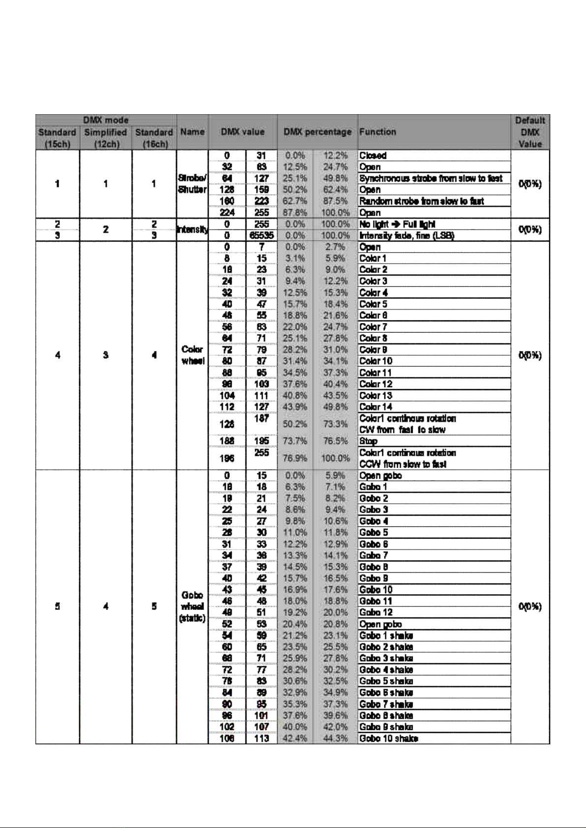
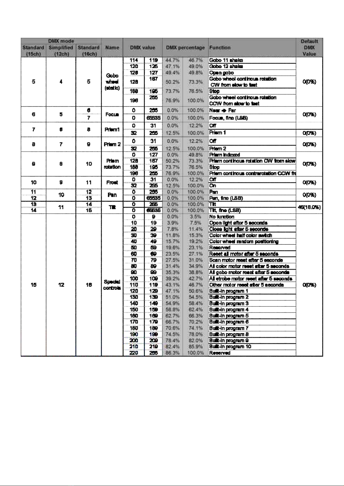
10. DMX Protocol
17

18
11. System wiring diagram
Table of contents
Other LCPRO Lighting Equipment manuals

Popular Lighting Equipment manuals by other brands

Vision & Control
Vision & Control DL30x30-R633/24V Instructions for use

Isolite
Isolite ELT2.0 ELITE Series Installation and operating instruction

batt led
batt led NEONFLEX installation guide

Cooper
Cooper HALO L2702 installation instructions

XanLite
XanLite PACK6SO1017 quick start guide

Varytec
Varytec Easy Move XS HP Wash user manual


