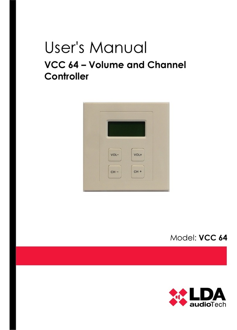
LDA Audio Tech VCC-64 User manual

User's Manual
VCC 64 – Volume and Channel
Controller
Model: VCC-64


Index
1 INTRODUCTION........................................................................................................................... 1
2 DESCRIPTION.............................................................................................................................. 1
2.1 INPUTS AND OUTPUTS.............................................................................................................. 1
2.1.1 DATA BUS / POWER SUPPLY...................................................................................................... 2
2.1.2 BUS ADDRESS............................................................................................................................. 2
3 CONNECTION.............................................................................................................................. 3
4 FUNCTIONING............................................................................................................................. 4
4.1 QUIESCENCE MODE...................................................................................................................4
4.2 ACTIVE MODE..............................................................................................................................4
4.3 AUTOMATIC LOCK......................................................................................................................5
5 FAULT RESOLUTIONS................................................................................................................ 6
5.1 SCREEN IS BLANK......................................................................................................................6
5.2 THE NUMBER OF SOURCES AND VOLUME SOES NOT APPEAR ON SCREEN.................6
6 MANTEINANCE INSTRUCTIONS................................................................................................ 6
7 TECHNICAL SPECIFICATIONS ................................................................................................. 7
Index of tables
Table 1: Data Bus / Power Supply......................................................................................... 2
Table 2: Volume - Zone Gain................................................................................................. 4
Table 3: Audio Source Screen................................................................................................5
Table 4: Technical Specifications...........................................................................................7
Index of illustration
Ilustration 1: Rear Side VCC-64.............................................................................................1
Ilustration 2: Address Switch..................................................................................................3
Ilustration 3: Bus connection..................................................................................................3

4 LDA Audio Tech - Severo Ochoa 31- 29590 MÁLAGA, SPAIN. Tlf: +34 952028805

SECURITY INSTRUCTIONS
1. Please read carefully these safety instructions.
2. Keep this User Manual for future reference.
3. Unplug the equipment from theAC before cleaning.
4. Do not use liquid or sprayed detergent for cleaning.
5. Use a cloth for cleaning.
6. Do not expose this equipment to humidity.
7. Install this equipment in a safe surface. If the equipment is not in a safe surface, it
may fall and be damaged.
8. The openings on the enclosure are for air convection. Do not allow overheat. DO
NOT COVER THE OPENINGS.
9. Place the power cord where people will not step or stumble. Do not place objects on
the power cord.
10.Always observe all warnings and precautions the equipment might indicate.
11.If the equipment is not used for several days, disconnect the power supply to
prevent damage from overloading. Never pour liquid into the openings, this could
cause fire or electric shock.
12.Never open the equipment. For safety reasons, the equipment should only be
opened by qualified personnel.
13.Pay attention to connection polarity when operating the machine with a power
supply (DC). Reverse connection polarity may cause damage to the equipment, or
to the power supply.
14.Let staff check the equipment if any of these situations occur:
a) The power cord or power plug is damaged.
b) Liquid has penetrated inside the equipment.
c) The equipment has been exposed to moisture.
d) The equipment does not work well or does not work according to the instruction
manual.
e) The equipment was dropped and damaged.
f) If the equipment has obvious signs of damage.
15.Disconnect the audio inputs and outputs while making connections. Be sure to use
the proper cables to make the connections.


User's manual: VCC-64
1 INTRODUCTION
The VCC-64 allows up to 64 programmable channels and volume control (0-9).
Usually installed in local zone and connected via bus to the system, it offers source
selection, volume control and lock function.
FEATURES:
1. Source selection (1-64)
2. Volume setting for the zone (0-9) – 10 steps per change
3. Automatic lock function
4. It shows the identifier of the music source routed to the zone
5. It shows the volume level asigned to the zone
6. Lock activated indicator
7. Connection of devices by bus mode
2 DESCRIPTION
The VCC-64 has a 2x8 character alphanumeric display where it shows the
information related to the zone of the PA system that is asigned.
2.1 INPUTS AND OUTPUTS
www.lda-audiotech.com 1
Ilustration 1: Rear Side VCC-64

2.1.1 DATA BUS / POWER SUPPLY
The VCC-64 has two poles for data connection through RS-485 protocol. It has a
power supply input of 12V DC with a consumption of 1,2W (100mA). The connector is
marked as J500. When the equipment has a power supply, the LED indicator marked as
power will be on.
The maximum number of units connected to the same interface is 8. The maximum
length (considering all sections) is 1000 m.
Mark Description Type Signal Activation
GReference for power supply (negative
pole) Input -Connect it to the negative pole of
the power supply
12V Continuous power supply (positive pole) Input +
Connect it to the negative pole of
the power supply. (max 100 mA / 1
V dc)
D- Serial connection port for integration
RS-485. Terminal D- Port D- Standard RS-
485/9600/8/SPACE/1
D+ Serial connection port for integration
RS-485. Terminal D+ Port D+ Standard RS-
485/9600/8/SPACE/1
Table 1: Data Bus / Power Supply
The connection uses a female Eurobock type connector (included with the
equipment) of 4 pins and 3,81mm pitch. The range of cable section for each pole of this
connector is 0,14 1,5mm2 (30 14 AWG).→ →
2.1.2 BUS ADDRESS
The VCC-6 has a DIP-Switch to configure the address in the bus RS-485. Every
controller assigned to the same zone, should have the same address configuration. For
different zones different address should be assigned.
2 LDA Audio Tech - Severo Ochoa 31- 29590 MÁLAGA, SPAIN. Tlf: +34 952028805

User's manual: VCC-64
3 CONNECTION
The VCC-64 is connected to the system's interface through bus mode, and every
VCC-64 will be connected from each other. Only one of the VCC-64 has to be connected
to the system's interface. This way the unit located closer to the system will be connected
to the interface, and from this unit to the next VCC-64. The last VCC-64 in the bus will not
have any connection to a consecuent device.
www.lda-audiotech.com 3
Ilustration 2: Address Switch
Ilustration 3: Bus connection

4 Operation
The VCC-64 has a 2x8 character alphanumeric display where it shows the
information related to the zone of the PA system that is assigned.
C H 4 9 V O L 9
B G M
4.1 QUIESCENCE MODE
During the quiescence condition, the display will indicate the music source assigned
to the zone, the volume level (0-9) and the lock indicator.
4.2 ACTIVE MODE
To unlock the device, press CH-, CH+ and then CH- back again. The lock indicator
will disappear from the display.
Once unlocked, press VOL+ to raise the volume level of the zone and VOL- to lower
it. The following table of equivalence shows the relationship between the volume indicated
in the VCC-64 and the gain associated to the zone.
4 LDA Audio Tech - Severo Ochoa 31- 29590 MÁLAGA, SPAIN. Tlf: +34 952028805

User's manual: VCC-64
VOLUME GAI
9 0dB
8 -3dB
7 -6dB
6 -10dB
5 -15dB
4 - 1dB
3 - 8dB
-36dB
1 -45dB
0 -100dB
Table 2: Volume - Zone Gain
To change the audio source assigned to the zone, press the buttons CH+ and CH-.
The display will show the change in the number of the source. The number displayed
corresponds to the number of the source in the PAsystem.
The audio source in the zone of the VCC-64 can be assigned remotely from the
main PA system's management or locally from the VCC-64.
The VCC-64 could select from any of the audio sources available in the system, up
to 64. By pressing CH+ or CH- we move from one to the next in a cyclic order.
The information relative to the audio sources that the VCC-64 will show, can be
seen in the following table.
DISPLAY DESCRIPTION
Chxx (01-64) BGM
Audio source No XX assigned
to the zone
MIC LOCAL A microphone is broadcasting
to the zone
Table 3: Audio Source Screen
www.lda-audiotech.com 5

4.3 AUTOMATIC LOCK
The VCC-64 has an automatic lock that will be activated after 25 seconds from the
last push of a button. To activate again the VCC-64, press CH-, CH+ and then CH- back
again. The lock indicator will disappear from the display.
5 FAULT RESOLUTIONS
5.1 SCREEN IS BLANK
If the display is blank, check the power supply. Verify if the wiring connection is
done according to chapter 2,2,1, If the power indicator light is on, reboot the system
disconnecting the power and reconnecting it again. If after restarting the system, still
nothing appears in the screen then contact Technical Support of LDA. If the power
indicator is off, the device is not receiving power and therefore will not work properly.
5.2 THE NUMBER OF SOURCES AND VOLUME SOES NOT APPEAR
ON SCREEN
If he number of sources and volume does not appear on screen, the driver indicates
to the system that there is no connection. Restart the device by disconnecting the power
and reconnecting it again. If the problem still persists and is not resolved, check the wiring
as described in section 3 . If after performing these tests the problem persists, contact the
support service of LDA.
6 MANTEINANCE INSTRUCTIONS
Generally the equipment requires a reduced periodical maintenance.
The frequency of maintenance should be adjusted depending on the installation
conditions of the system.
Warnings:
•Use only a soft, lint-free cloth to clean the system.
•Disconnect the device from any external power source.
•Disconnect all external devices.
•Keep it away from any liquid.
•Do not use aerosol sprays, solvents or abrasives.
•Do not spray any cleaning products directly on the device.
Operations:
•Wipe the system with a damp cloth.
6 LDA Audio Tech - Severo Ochoa 31- 29590 MÁLAGA, SPAIN. Tlf: +34 952028805

User's manual: VCC-64
7 TECHNICAL SPECIFICATIONS
Model VCC-64
Reference LDAVCC64S02
Power supply 1 V DC
consumption 1, max (100mA)
Bus RS-485 Maximum distance 1000m/ 3 80,8 ft. MAX 8 VCC-64 by bus
Address Dip-swithc 3 bit
Volume Buttons VOL- / VOL+
Volume Steps 0-9
Source Buttons CH+ / CH-
Channel Range 64 / 01 BGM + MIC LOCAL
Functioning Conditions -5ºC to +45 ºC / 3 ºF to 113 ªF
5% to 95% Relative Humidity (without condensation)
Finishing ABS RAL 9016
Weight 110gr 3,88 oz
Drill Installation (HXWXD) 6 mm x 70mmx 35mm / ,44” x ,75 x 1,38
Dimensions (HxWxD) 86mm x 86mm x45mm / 3,38 x 3,38 x 1,77
Power supply 1 V DC
Consumption 1, max (100mA)
Bus RS-485 Maximum distance 1000m/ 3 80,8 ft. MAX 8 VCC-64 by bus
Table 4: Technical Specifications
www.lda-audiotech.com 7

Rev 3,1
Other manuals for VCC-64
1
Table of contents
Other LDA Audio Tech Controllers manuals
Popular Controllers manuals by other brands
Zhejiang Dahua Vision Technology
Zhejiang Dahua Vision Technology Face Recognition Access Controller user manual
YASKAWA
YASKAWA iQpump1000 Installation & start?up guide
Mitsubishi
Mitsubishi FX3U-64CCL user manual
Asco
Asco SentronicD 608 Series installation manual
Mitsubishi Electric
Mitsubishi Electric MELSEC iQ-R Series user manual
Interflex
Interflex IF-4076-0 manual
