Installation
• Vent system must terminate to the outside (roof
or side wall).
• DO NOT terminate the vent system in an at- tic
or other enclosed area.
• DO NOT use 4” (10.2 cm) laundry-type wall
caps.
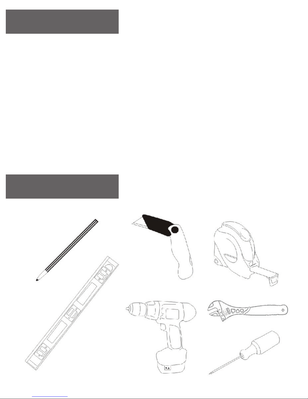
• Use metal /aluminum vent only. Rigid metal
(Not Included).
aluminum vent is recommended.
• DO NOT use plastic vent.
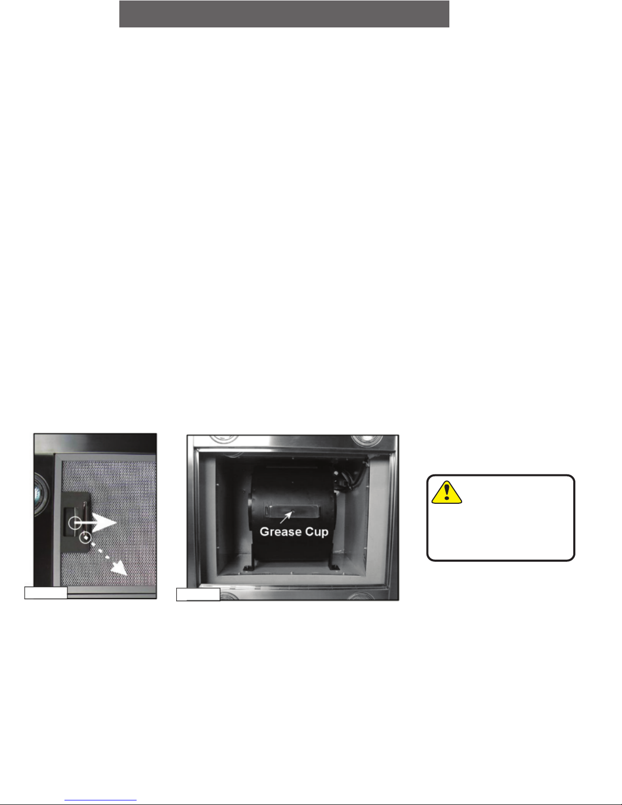
•Always keep the duct clean to ensure proper
airflow.
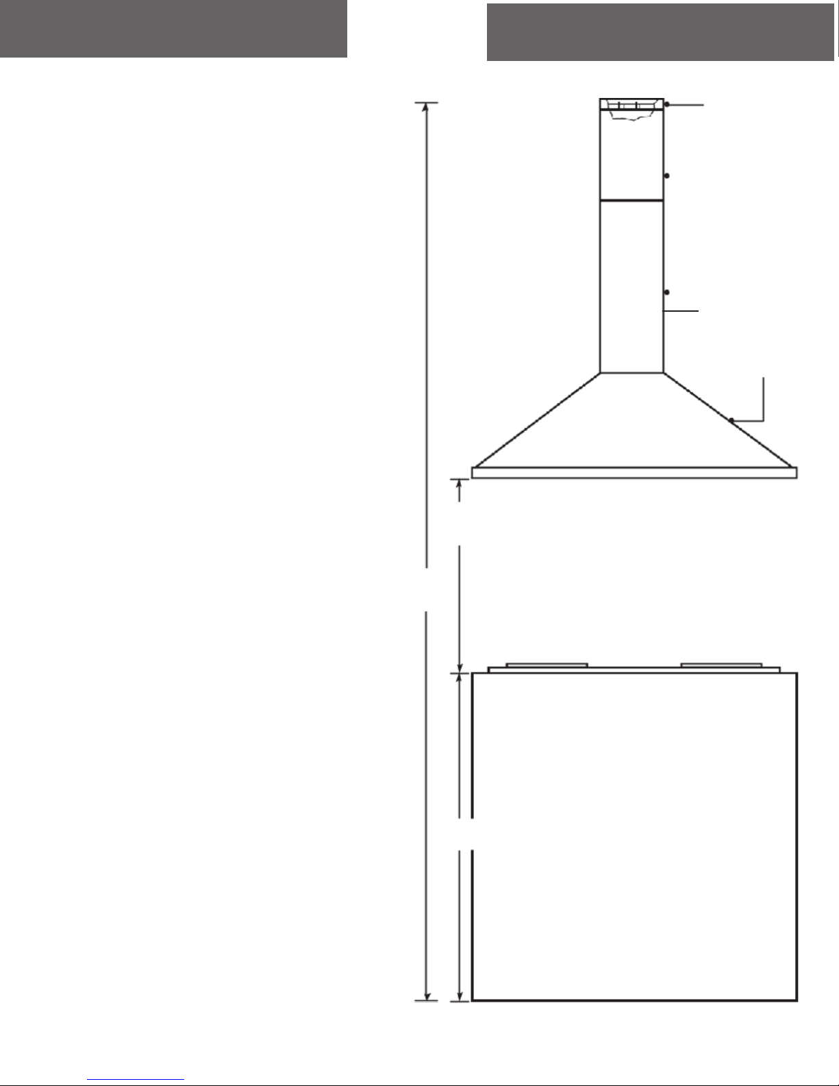
• Calculate the following figures before
installation:
1.Distance from the floor to the ceiling.
2.Distance between the floor to the coun-
tertop/stove (Usually 36 Inches).
3.Distance between the countertop/stove to the
range hood.
We recommend (25.5’ to 27 1/2’ Inches).
4. Height of hood and duct cover.
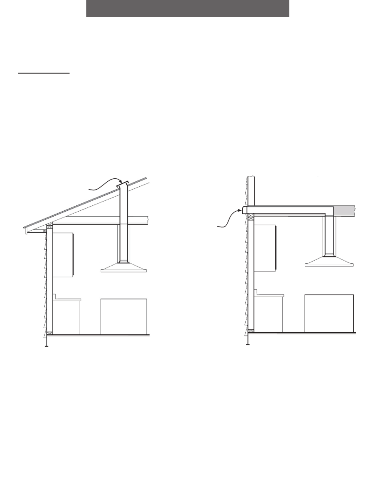
For the most efficient & quiet operation:
• It is recommended that the range hood be
vented vertically through the roof through 6”
(15.24 cm) or bigger round metal / aluminum
vent work.
• The size of the vent should be uniform.
• Use no more than two 90° elbows.
• Make sure there is a minimum of 24” (61 cm)
of straight vent between the elbows if more than
one elbow is used.
• DO NOT install two elbows together.
The length of vent system and number of
elbows should be kept to a minimum to pro- vide
efficient performance.
• The vent system must have a damper. If roof
or wall cap has a damper, DO NOT use damper
(if supplied) on top of the range hood.
• Use silver tape or duct tape to seal all joints in
the vent system.
• Use caulking to seal exterior wall or roof open-
ing around the cap.
10
1. Align upper support frame with holes in the ceiling. Mount the
upper support frame to the ceiling using four “A” screws
(for sheet rock only). Make sure that the upper support frame
is securely fastened to the joint or support in the ceiling. Attach support frame to the ceiling using
ONLY the anchors recommended for your type of ceiling.
• Sheet rock ceiling: Attach support frame to ceiling joists or stud blockings if possible. If ceiling joists or
stud blockings are not available, it is required to build a supporting structure behind the sheet rock for
best weight support.
• Concrete ceiling: Use designated screws (not provided).
• Wood ceiling: Use at least 4” long wood screws (not provided).
2. Position the support frame extensions at the inside corners of the support frames, adjust and mark
each support frame extension as necessary to achieve the proper height for the range hood to be set
away from the cook top. (See Height and Clearance on Page 5 and Installation Overview on next page).
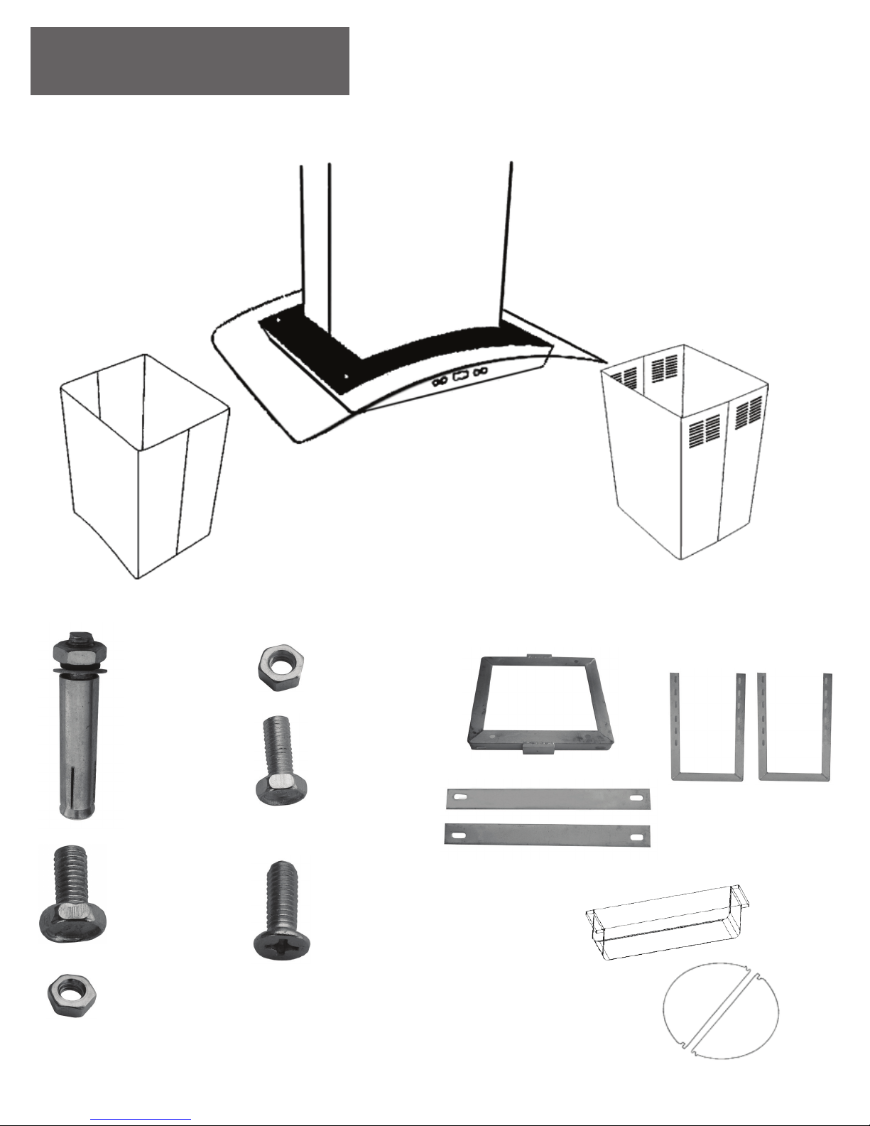
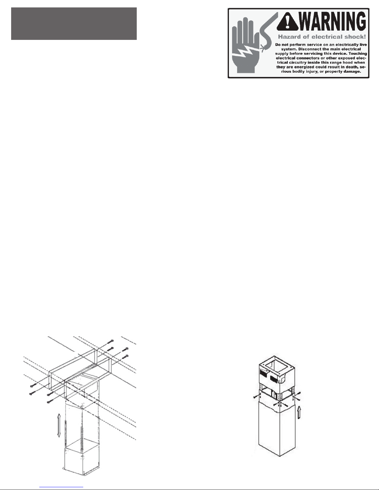
3. Fasten the support frame extension onto the lower support frame using four “B” bolts and “C” nuts as
shown in Figure 3. Repeat this step for rest of the support frame extensions. IMPORTANT: Always use
first and second holes on the support frame extensions.
4. Calculate the height of the duct tube and extend approximately 6 inches longer than required, connect
the upper end of the duct tube to the vent system.
5. Position the lower support frame with support frame extensions to the upper support frame, fasten
each extension with four “B” bolts and “C” nuts as shown in Figure 3.
7. Slide the upper chimney cover over the completed support frame and fasten with two “F” bolts to the
upper support frame. (See Figure 3 for illustrations).
8. Slide the lower chimney cover around the lower sup- port frame and around the upper chimney
cover. Have second person to hold it in position. (See Figure 4).
`
Adjust
support frame
extensions
Secure upper
support frame.
Slide up and secure
upper chimney.
Slide up, hold in position and
secure lower chimney
to range hood
Insert lower
support
frame with
extensions
Stud blockings
Figure 4
Figure 3