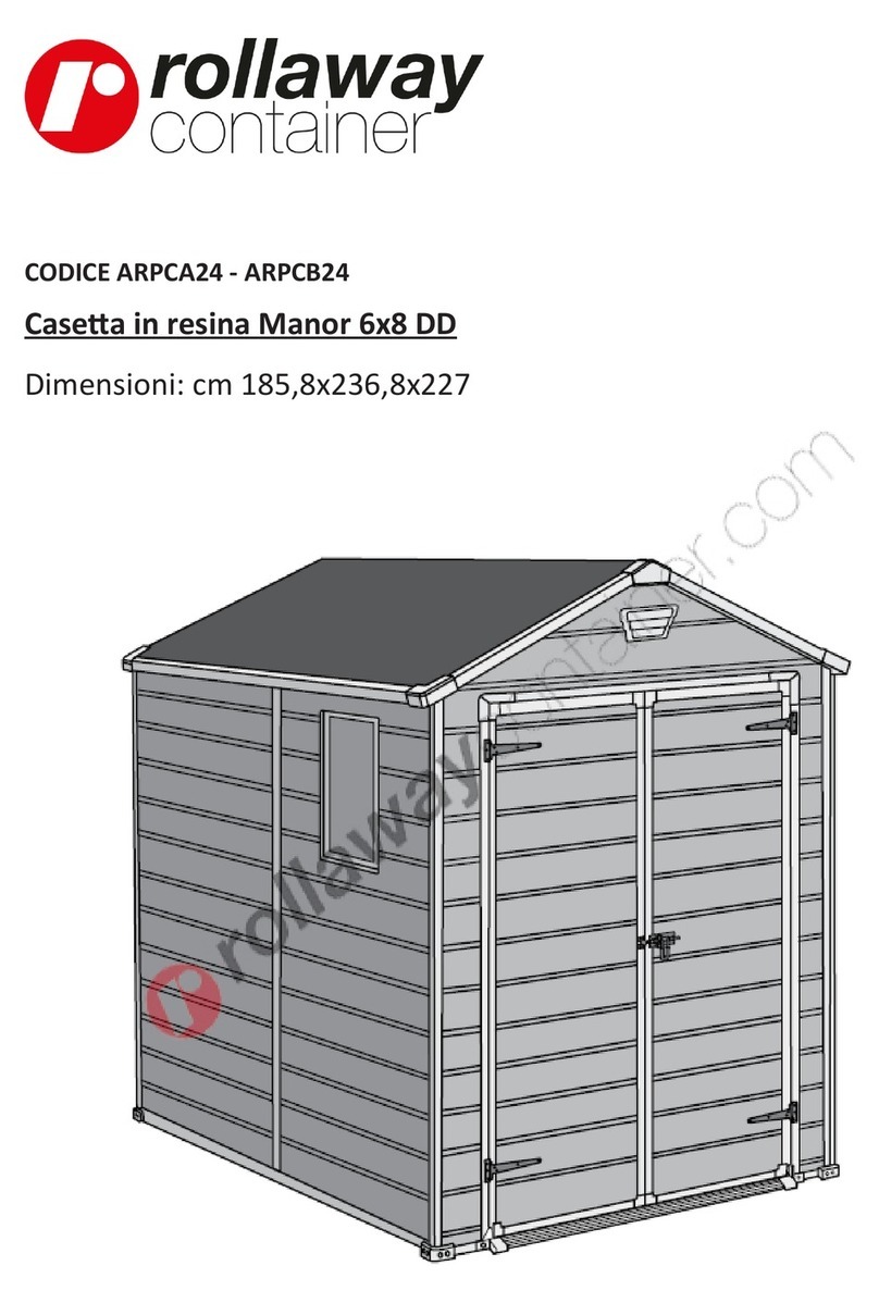
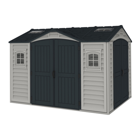
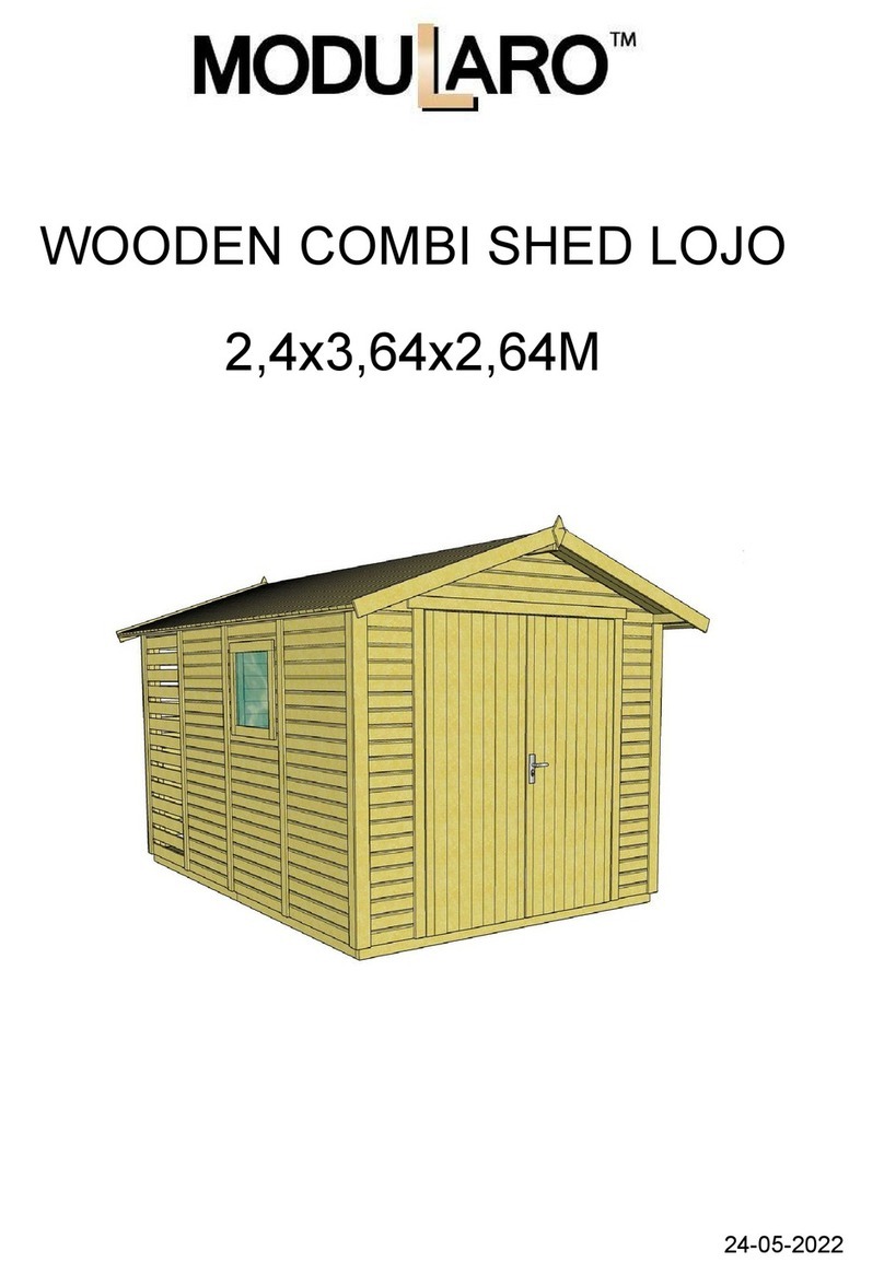
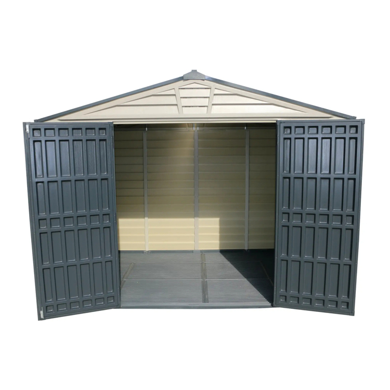
LeisureSeason WPC110757 User manual

76 sq.ft.
WPC110757
11’ X7’
INSTALLATION INSTRUCTIONS
2.36” 83.62” 1.97”
136.61” 3.15”3.15”

2
INSTALLATION INSTRUCTIONS AND RECOMMENDATIONS
•Remove all parts from the packaging and lay themout on a clean work surface in Zone I/II and III.
• Please read the list of components BEFORE assembly, making sure that no parts are damaged or missing.
• Read through the complete assembly instructions again.
• Assemble all parts according to the instructions in this manual and do not skip any step.
• For shed construction and handling, please use only the tools listed in the assembly instructions.
• Always wear work gloves, safety glasses, and any other type of long-sleeved clothing during shed assembly or any
type of maintenance work.
• Treat wall panels with extreme care before and during assembly. Place them carefully on the ground.
• Avoid walking on them or placing objects on them.
• At least two people are required to assemble the shed.
• Recommendation: Build a base of wood/composite or concrete as a foundation.
• Allow sufficient space at the installation site outside the shed to access it from the outside during assembly.
• Do not install in cold or windy weather. Wind direction is an important factor that must be considered when placing the
shed on your property. Choose a suitable location where there are no excessive winds to prevent high wind pressure
on the doors.
• Due to the high proportion of composite material, the surface may have different color shades. This does not mean that
special treatment is required or that it will affect the shed’s lifespan.
• Do not use aggressive cleaning agents as they can stain or damage the WPCshed.
CARE, MAINTENANCE AND SAFETY INSTRUCTIONS
Δ The shed is generally used for storing objects. The shed is not especially designed for residential purposes.
Δ Check the shed regularly for stability and make sure that the location is level.
Δ Be careful when handling parts with steel edges.
Δ For the construction and handling of the shed, please only use tools that are listed in the assembly instructions.
Δ Avoid using lawnmowers and mechanical scythe in the immediate vicinity of the shed.
Δ To clean the shed, start by rinsing it with a garden hose to remove surface debris. Then you can use a soft-bristled
brush with warm soapy water.
Δ Do not damage, gouge, scrape or puncture any surface of the shed, using metal shovels or sharp-edge tools to remove
snow and ice on any surface of the garden shed or in any other way. Instead, use a plastic shovel and recommended
calcium chloride or rock salt to melt snow and ice.
Δ Do not paint, stain or apply other coating materials or any other chemical substances, including detergents or
pesticides to the shed.
Δ Clean oil or grease spills as soon as possible and at the latest within seven days. Start by rinsing with a garden hose
and use warm soapy water and a soft-bristled brush. If that’s not enough, you can use recommended all-purpose
cleaners, including for composite, and follow the manufacturer’s instructions carefully.
Δ Do not store any hot objects in the shed, such as recently used grills or blowtorches, or any volatile chemicals.
Δ Do not lean heavy objects against the walls of the shed, as it could deform the entire structure.
Δ Keep the roof free of snow and accumulated foliage. Large amounts of snow can damage the shed and make it
dangerous for entering.
Δ Ensure there is adequate ventilation in the shed to prevent excess moisture.
Δ Always keep the doors closed and locked when the composite shed is not in use to avoid any kind of wind damage.
Δ If there is mold present, you can use a garden hose and warm soapy water with a soft-bristled brush. If that’s not
enough, you can use recommended cleaners, including for mold, and follow the manufacturer’s instructions carefully.
Δ Avoid direct water projection from an automatic watering system onto the composite boards or other parts of the shed,
as this water could cause permanent stains where it hits the surface.
2
ENGLISH
No Structure Description QTY Code
Aluminum Bottom
Frame (Front & Rear)
1.38” H X 0.79” D X 68.58” L2M1107
35.2-30-1742-1
Aluminum Bottom
Frame (Front & Rear)
1.38” H X 0.79” D X 68.58” L2M1107
35.2-30-1742-2
Aluminum Bottom
Frame (Left & Right)
1.38” H X 0.79” D X 83.62” L2M1107
35.2-30-2124
Aluminum Column
(Left Front)
2.32” H X 2.32” D X 87.48” L1Left front column
M1107
59-59-2222
Aluminum Column
(Right Front)
2.32” H X 2.32” D X 87.48” L1Right front column
M1107
59-59-2222
Aluminum Column
(Left Rear)
2.32” H X 2.32” D X 79.06” L1Left rear column
M1107
59-59-2008
Aluminum Column
(Right Rear)
2.32” H X 2.32” D X 79.06” L1Right rear
column
M1107
59-59-2008
Aluminum Threshold
2.32” H X 1.18” D X 53.23” L1M1107
59.3-30-1352
Aluminum Door
Frame (Left)
1.18” H X 1.06” D X 73.82” L
1Left front column
M1107
30-26.9-1875
Aluminum Door
Frame (Right)
1.18” H X 1.06” D X 73.82” L
1R i g h t f r o n t c o l u m n
M1107
30-26.9-1875
Aluminum H-shaped
Beam (Front & Rear)
2.09” H X 0.94” D X 67.09” L4M1107
53-23.9-1704
Aluminum H-shaped
Beam (Front & Rear)
2.09” H X 0.94” D X 80.63” L2M1107
53-23.9-2048
Aluminum Verge Board
(Front & Rear A)
3.15” H X 1.77” D X 71.46” L2M1107
80-45-1815-A
Aluminum Verge Board
(Front & Rear B)
3.15” H X 1.77” D X 71.46” L2M1107
80-45-1815-B
Aluminum Verge Board
(Left & Right)
3.15” H X 1.77” D X 87.80” L2M1107
80-45-2230
Aluminum H-shaped
Column
1.97” H X 0.79”D X 12.68” L1M1107
50-19.6-322
Aluminum Beam
2.83” H X 1.97” D X 134.88”
L
6M1107
75-45-1713
Window (Front)
66.57” H X 12.68” D 2M1107
1691-322
Window (Left Side)
80.51” H X 12.64” D X 4.21”
L
1M1107
1996-322
3
4
3
7
9
13
17
15
16
18
14
12
11
10
1-1
1-2
8
2
6
5

No Structure Description QTY Code
Window (Right Side)
80.51” H X 12.64” D X 4.21”
L
1M1107
1996-322
Color Steel Tile
33.07” H X 87.80” D5
Double Door
53.15” H X 72.05” D1
Composite Wall Panel
6.69” H X 0.79” D X 73.82”L36
Composite Wall Panel
6.69” H X 0.79” D X 77.32”L20
Aluminum connectstrip
2.72” H X 1.85” D X 23.62 L 3M01107
69-47-600
25 Aluminum connectstrip
0.78” H X 0.78” D X 23.62 L 2M1107
19.8-19.8-600
Screws
8X80 20
Screws
4X16 300
Screws
#6 x 30mm 16
DConnector
50X50 6
Screws
5X20 12
Screws
5X45 66
Screws
5X60 18
Latch 2
Plastic Cap for Aluminum
Verge Board 4
Door Lock Kit 1
Small stick
5X13 2
4
20
23
21
24
22
19
G
A
H
C
B
K
J
E
L
F

TOOLS REQUIRED FOR INSTALLATION
8 m m
8
COMPOSITE SHED THREE-VIEW DRAWING
142.91”
87.56”
AXONOMETRIC VIEW
TOP VIEW
137.17”
FRONTVIEW
83.62”
SIDE VIEW
137.17”
134.17”
83.62”
80.63”
EN
87.48”
87.48”
77.32”
73.82”
73.82”
79.06”
EN
5

EN Composite shed should be installed on the hard ground like concrete foundation, the
surface of ground should be flat and the size should follow the dimension of drawing.
GROUND REQUIREMENTS
.
EN Bottom Beam Dimension Drawing.
6
86.61”

10
B11.81”
25
10
x2
EN Please note that the notching is in the same direction.
11.81”
B
16 16
x3
7
16 16 16
C
16
D
EN After prepare the installation area for your composite shed, please check parts according to
the part list firstly, then place those parts on site, and assemble the following parts in advance.
EN Connect the aluminum beams with L brackets by applying screws in advance.
24
16
16
16
D
C

EN Install aluminum bottom frames according to dimensions and positions as the sketch
map shown above,then fix them with plastic expansion bolts. Please make sure the
leveling of the bottom frames.
8
A
20xA
1-1
1-2
1-2
2
1-1
2

9
EN Install the shed from the front side, please insert column (left & front) and composite wall
panel into the groove of aluminum bottom frames, then fasten column and planks with
screws. Two operators are required for this step, one needs to hold the column so as to
avoid any broken caused by tilt. (We suggest to install composite shed under the calm
weather, and more operators are needed if install under windy weather). Use a sealant
gun to apply a bead of sealant inside the column, following the red line.
12
2
21
22
21
22
1
3
3
B

EN
Install the composite wall panel one by one.
1-2
1-1
2
3
22
5
1-1
2
1-2
EN
Install the column (left & rear) into place. Use a sealant gun to apply a bead of
sealant
inside the column, following the red line.
10
22
3
1-2
2
1-2
2
1-1
1-1
22

EN
Install the composite wall panel one by one.
5
311
22
23
1-1
2
21-2
1-1
1-2
EN
Insert the aluminum H-shaped beam (left/right) into the column, then install
the
composite wall panel into the place one by one.
11
11
1-2
1-1
1-1
2
5
1-2 2
22
3

EN
Install the aluminum column (right & rear) into the place, then insert the
aluminum
H-shaped beam (rear) into the column.
6
10 11
4
5
11
22
23
3
22
2
1-2
2
1-1
EN
Install the aluminum column (right & front) into the place, then insert the
aluminum
H-shaped beam (left/right) into the column.
12
3
6
23
5
22
1-1
2
1-1
10
2
1-2
1-2
11

13
22 X6
22 X6
EN Install front composite wall panel and aluminum H-shaped beam (front) into the place.
11
10
10
11
10

EN After adjustment, please ix the composite wall panel, aluminum bottom frame and
aluminum H shaped beam with screws, two screws are required in the connection of
every composite wall panel and beams.
7
7
EN Insert the left and right aluminum door frames into the position, then install the aluminum
threshold, and adjust perpendicularity and dimension between the two frames shown as
the above sketch map.
853.15”
9
B
14

EN Install window into the place. (Please note different sides of window, the side with rivets
should be toward the inside)
EN Fasten the window with columns and H-shaped beams by using screws.
15
17
17 18
19
15

EN Connect the aluminum beams with window (left & right side) by using screws.
19
16 16 16
16
16

17
IMPORTANT
3.15” 2.36”
EN Install the color steel tile, the extension length of roof tile should be 2.36” in the shed’s
front side, while the left and right side should be 3.15”. Please note that the length of
screws for roof tiles ixing is different from those for the connection with aluminum beams.
F
E
FE
FE
F
20
G
E
E

IMPORTANT: When installing the roof, you must respect the measurements on page 17. When the panels are installed,
screw a first screw on the right and another on the left, respecting the measurements on page 17. Make a line at using a
chalk-line or a level to be sure to follow the aluminum beam of the roof and put the screw in it.
18
EN Install roof tiles one by one, please pay attention to the connection method shown as the
above sketch map.
20
20 20
20 20

EN Install all aluminum verge boards inline with the diagram as above.
22
13
13
14
J
12 14
12
J
J
J
19

300mm 250mm
300mm 250mm
This type of hinge fits both left and right sides, you can remove the axis pinto
adjust the left or right in accordance with actual requirement, please press the
cap tightly on both ends after the installation.
Please install the door with following steps:
- Assemble the hinge on the door with rivets(see diagram above);
- Place the door in the position where needs to install it;
- Put a subplate with a thickness of 5mm under the door;
- Insert the other side of hinge into the place, and mark the position with a pencil;
- Remove the door, then fix hinges with rivets.。
After fix the hinge, hang the door in the knuckles from the top downwards.
20
Table of contents
Popular Outdoor Storage manuals by other brands

Lifetime
Lifetime 60310 Assembly instructions

OLT
OLT SpaceSaver SS84D-FJ-METAL Assembly manual

Hoggar
Hoggar Formentera user manual

Asgard
Asgard FLEXISTORE 1511 manual

Rutland County Garden Furniture
Rutland County Garden Furniture Empingham Assembly instructions

SPACEMAKER
SPACEMAKER RGB1010ONEU Owner's manual & assembly instructions

Mercia Garden Products
Mercia Garden Products 03COR0707-V4 General instructions

Kingfisher
Kingfisher OSPROMO Assembly instructions

Arrow Storage Products
Arrow Storage Products WR106 Owner's manual & assembly guide

Shire
Shire 7x7 Cornershed Assembly

Keter
Keter EMILY 280 L Assembly instructions

ABSCO SHEDS
ABSCO SHEDS 30151SK Assembly instructions