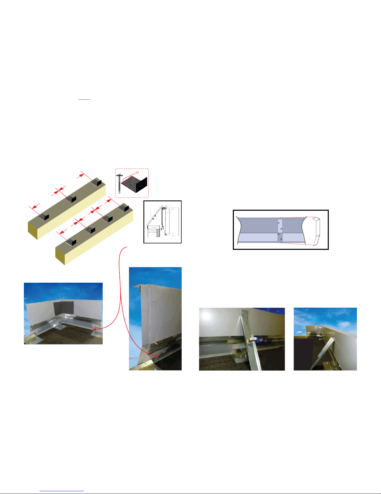
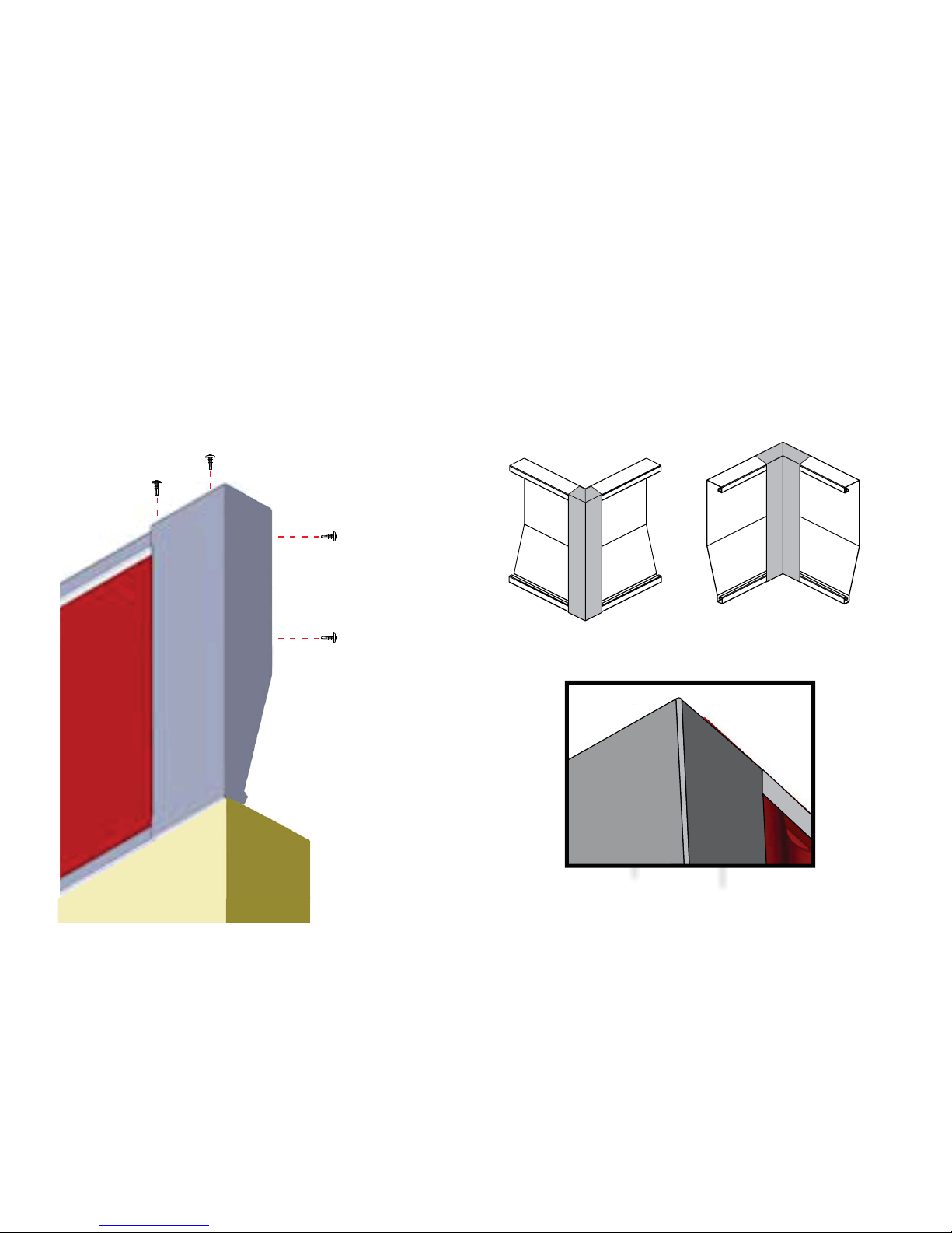
MOUNTING SURFACES VARY
PLEASE USE PROPER SCREW WHEN MOUNTING THE
HOUSING TO THE STRUCTURE
HEX HEAD TEK SCREW WITH NEOPRENE WASHER IS
PROVIDED AND NOT TO BE USED WITH MATERIAL OTHER
THAN METAL
GETTING STARTED CONTENTS
Following these few simple steps will ensure a successful installation each time.
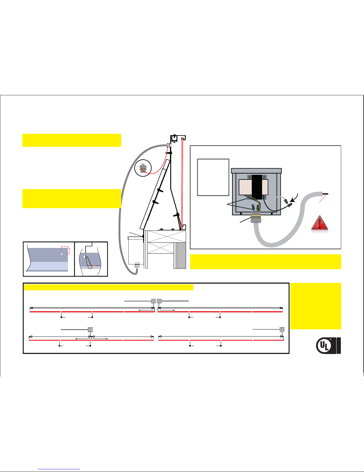
Remember: No more than 32 boards per transformer.
1. Instructions, before starting Installation.READ ALL
2. Unpack your crate check the parts against the supplied parts list.
Report damaged parts or shortages immediately to preventNote:
job slowdown /stoppage to 1-800-634-4059 ext. 0.
3. Refer to attached provided print and con rm job measurements.
4. Layout your job on paper, making note of transformer
placement. Transformers can be placed in 3 con gurations.
If job measurements do not correspond to providedNote:
drawing, call Lektron immediately at 1-800-634-4059.
1
2
3
4
5
6
7
SEC. Page
Getting Started, Contents, and Installation Check list
1. Component Identi cation & Required Tools.............................................................................
2. Proper Measuring & Placement Of The Lightband.................................................................
3. Installation of Cut Section & Sizing the LED.............................................................................
4. Setting the Transformer............................................................................. ......................................
5. Testing Each Section..........................................................................................................................
6. Lens Installation..................................................................................................................................
7. End Cap Installation..........................................................................................................................
LED SPECIFICATIONS
ELECTRICAL
CERTIFIED
SAFETY US CA
Output
Input
Power Rating
Maximum Load
(In a Single Direction)
Current at Max. Load
25 VAC
120 VAC
100 VA
32 12" Boards 20L
.55A
=
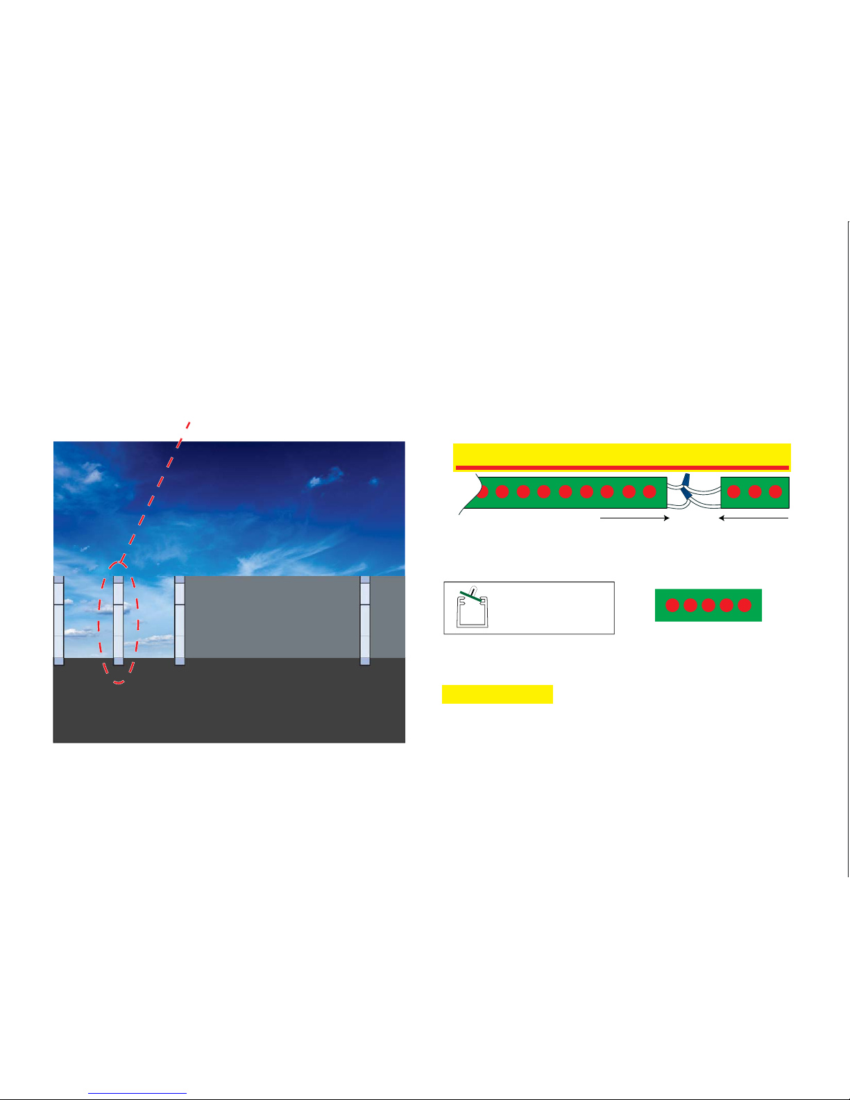
12" LED boards pull close to the same voltage as shorter
break-apart boards. Maximum of 3 - 3" Boards per circuit.
No more than 32 boards on a circuit. Do not connect more
than one transformer per circuit.
INSTALLATION SEQUENCE
Belowwehaveidenti edasequenceofoperationsthatwillguideyouinthe
proper installation of the parapet band system. However, always be aware of
your surroundings and site conditions that cannot be taken into consideration
when writing this guideline. It is always your responsibility to ensure a safe and
clean workplace environment. if they are different from what was1. Review the onsite construction plans;
supplied withthe parapet band system or if you are missing anycomponents in
the system call Lektron LED Technologies at 1-800-634-4059 immediately.
It is recommended that you start your installationwith a corner, and then
work to the towers or the back of building. This will allow the smaller section
of cut housing to be on the end opposite of the corners. By doing this it will
eliminate two small sections of housing being close to one another.
reference “Installing the Mounting Brackets” for2. Install mounting brackets;
proper installation procedures.
3. Install string line it is recommended that you install aor laser level;
string line 151/4”up from the top of the parapet wall to properly align the
top of the housing and corners.
4. Set corners into place; reference “Installing the Inside and Outside Corners”
for proper installation procedures.
reference “Installing the Housings” for proper5. Set housing into place;
installation procedures. reference “Installing Adjustment6. Install remaining adjustment brackets;
Brackets” for proper installation procedures.
reference “Installing LED's” for proper installation procedures.7. Install LED's;
8. Install the transformers;it is critical to test the LED's for proper operation
prior to installing the lens.
9. Install the lens; reference “Installing the Lens” for proper insta llation
procedures.
10. Install the end and corner caps; reference “Installing the End Caps” and
“Installing the Inside and Outside Corners” for proper installation procedures.
11. Inspect to insure parapet band system looks and operates correctly.