manuals.online logo
Brands
  1. Home
  2. •
  3. Brands
  4. •
  5. LEMANIA
  6. •
  7. Watch
  8. •
  9. LEMANIA CH 27C12 User manual

LEMANIA CH 27C12 User manual

Popular Watch manuals by other brands

Casio QW 5513 Operation guide

Casio

Casio QW 5513 Operation guide

Piaget 560P Instructions for use

Piaget

Piaget 560P Instructions for use

Armitron pro sport MD0346 instruction manual

Armitron

Armitron pro sport MD0346 instruction manual

West Marine BlackTip 13411293 Instruction Booklet and Care Guide

West Marine

West Marine BlackTip 13411293 Instruction Booklet and Care Guide

Jaeger-leCoultre HYBRIS MECHANICA CALIBRE 184 manual

Jaeger-leCoultre

Jaeger-leCoultre HYBRIS MECHANICA CALIBRE 184 manual

FOREVER iGO PRO JW-200 user manual

FOREVER

FOREVER iGO PRO JW-200 user manual

Relic OS10 quick start guide

Relic

Relic OS10 quick start guide

MyKronoz ZeClock manual

MyKronoz

MyKronoz ZeClock manual

Casio QW-782 General guide

Casio

Casio QW-782 General guide

Strikes and Spares SASM80 E-manual

Strikes and Spares

Strikes and Spares SASM80 E-manual

Christopher Ward C1000 Owner's handbook

Christopher Ward

Christopher Ward C1000 Owner's handbook

Lotus ILMFS01 instruction manual

Lotus

Lotus ILMFS01 instruction manual

Chronos Manufactures Chrono Diamond Thyrso 10400 instruction manual

Chronos Manufactures

Chronos Manufactures Chrono Diamond Thyrso 10400 instruction manual

Pandora WATCH2 quick guide

Pandora

Pandora WATCH2 quick guide

Suunto X6 user guide

Suunto

Suunto X6 user guide

Seiko N830 instruction manual

Seiko

Seiko N830 instruction manual

MotionX 365 user guide

MotionX

MotionX 365 user guide

Aplus GV18 user guide

Aplus

Aplus GV18 user guide

manuals.online logo
manuals.online logoBrands
  • About & Mission
  • Contact us
  • Privacy Policy
  • Terms and Conditions

Copyright 2025 Manuals.Online. All Rights Reserved.

IDENTIFICATION OF CHRONOGRAPH
IJli'IDIHD
~
-
---;-'''''-'''''
I2L
LEMANIA CAL. CH 27C12
..
.
'.
...
':.
.
-.;....
"
.
INSTRUCTIONS
For use of book
DISASSEMBLY OF THE CHRONOGRAPHMECHANISM:
1. Study the isometric drawing at top of page I-A. The isometric drawing was
made for the following purposes:
A. It helps to identify the part to be removed.
B. This drawing aids in pointing out certain locations on the part
that are mentioned in the oiling procedure.
C. The text refers to certain points on the part. These points are
shown in the isometric drawing. This should aid you in finding
the exact location on the part that is described in the text.
D. It helps you to know the shape of the part in case a new part has
to be made.
2. At the bottom of the page I-A is a photograph of a chronograph. In this photo-
graph is the same part painted in black. The part is in its exact location that this
part occupies in the watch. Find this location in the watch.
3. Read the disassembly procedure and the hazards in disassembly on page 1 in
this book.
4. Remove this part in the same procedure as described in the text.
5. A very imp-ortant item in disassembling a chronograph is keeping the screws in
order, much time will be lost in putting the chronograph together
if
screws are
mixed up. This means you have to hunt for each screw, sometimes trying three or
four screws before finding the correct one. It cannot be stressed too strongly that
care should be taken so that screws are not mixed up. The system that we advise
for beginners, is to replace each individual screw after each part is removed. This
naturally eliminates the hazard of mixing up the screws and will save you much time
in the end. Do this at least until you become so thoroughly familiar with the
chronograph that you no longer feel it is necessary.
6. Continue to follow this procedure throughout the book and disassemble each part
until the last part of the chronograph is removed.
ASSEMBLYOF THE CHRONOGRAPHMECHANISM:
7. Whenyou are ready to assemble the chronograph mechanism, study the isometric
drawing on the last part in this book. This drawing should aid you in identifying the
part to be assembled.
3. At the bottom of this page is a photograph of a.chronograph. In this photograph
is the same part painted in black. The part is in its exact location that this part
occupies in the watch.
9. Read the assembly procedure and the hazards in assembling for the last part
in this book. (Continued on next page)
.
~:""
.
II
I.
INSTRUCTIONS
(Continued)
10. Replace the part in its exact location as shown in photograph, using the procedure
as described in the text.
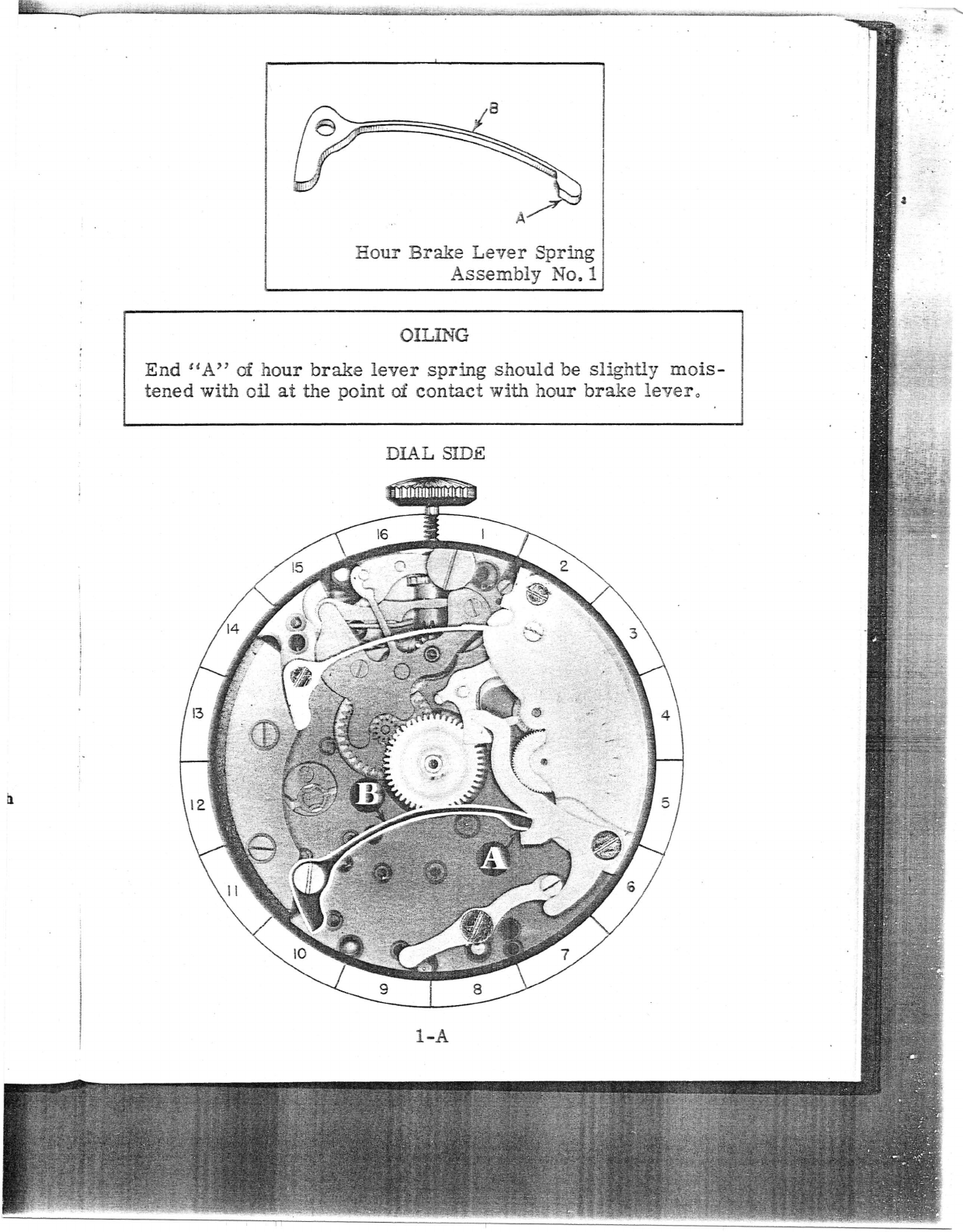
11. After you find the correct location for this part in the watch, read the oiling
procedure for this part. The oiling procedure for this part is located underneath
the isometric drawing. It is best to read the oiling procedure before you put each
part in place as there are certain parts that must be oiled immediately as it may
prove difficult to oil them later.
..
-.
~
..
12. Replace the screw that holds this part in place. Of course, the screws should
be kept in order as we advised above, but if the screws are not in order or the watch
was received with screws mixed up, you will find a screw drawn for each part that
requires a screw at the bottom of the text page.
13. After replacing this part, replace the next part, etc., until the last part is
replaced, which will be part No.1. Each part should be replaced using the same
procedure as described in the text.
(Naturally, the assembly of the chronograph is exactly the reverse of the disassembly)
14. After disassembling and assembling the chronograph mechanism, start on page
1 and read the function of this part. After reading the function of this part, continue
to read the function of each part throughout the book. Study each part, one at a
time. This text should help you to understand more fully the purpose of each part
in the chronograph mechanism.
15. Now put movement in its case with dial on, then replace hands.
,0
I.
16. Study the text on functional results in this book, and check the chronograph
mechanism as described in this text.
NOMENCLATURE OF PARTS FOR CHRONOGRAPH MECHANISM
17. After you have become familiar with the Chronograph mechanism, you can
disassemble and assemble the chronograph by using the nomenclature of parts as a
.guide. This makes it possible for you to use a procedure without going through each
page in the book.
18. ADJUSTMENTOF ECCENTRICSTUDS:
Read the text on adjustment of eccentric studs, this text should be read in reference
to the eccentric stud picture. Now adjust each eccentric stud one at a time in the
watch, as described in the text. Use the picture to show you the position of these
studs.
19. On each page in this book the part number and the page number are the same.
This makes it convenient for the reader and eliminates any confusion.
I~.
NOMENCLATURE OF PARTS FOR
CHRONOGRAPH MECHANISM
Hour Brake Lever Spring
Assembly No.1
Hour Flyback Lever Spring
Assembly No.4
Connecting Lever
Assembly No. 3
A
Hour Flyback Lever
Assembly No. 5
Push Piece for Setting Back
to Zero Assembly No. 7
A
Hour Brake Lever
Assembly No. 2
Barrel Bridge Assembly No.5
Hour Register Wheel
Assembly No. 8 Hour Wheel Assembly No.9
Wheel Over Fourth Wheel
Assembly No. 10
Brake Lever
Assembly No. 19
Actuating Lever for Hour
Brake Assembly No. 11
Intermecilary Wheel
Assembly No. 14
A
Actuating Detent Lever
Assembly No.1 7
Chronograph Pivoted Detent ana
Actuating Detent Lever Spring
Assembly No. 12
Chronograph Pivoted Detent
Assembly No. 15
~.
I
A
Jotnt Hook Assembly No. 18
Flyback Lever Spring
Assembly No. 20
A
(Continued
on Next Page
Minute Register
Pawl Spring
Assembly No. 23
t
.' .\.
NOMENCLATURE OF PARTS FOR
CHRONOGRAPH MECHANISM
Minute Register Pawl Bridge
Assembly No. 21
.<
C
Trip Pin Spring
Assembly No. 30
Minute Register Hand
Minute Register Pawl
Assembly No. 22
intermittent Lever Spring
Assembly No. 28
~)
Trip Pin
Assembly No. 31
""""mbly No. 34
~
Driving Pinion Tension Spring
and Dr, .ving.Pinion.
Hour Register Hand
A
Seconds Wheel Tension Spring
Assembly No. 26
"
j
\.1
I'
I'
f
Assembly No. 29
I
t
Castle Wheel Pawl
Assembly No. 32
Sweep Second Hand
of'
••
,Listedt
1. With
gage
COR
2. With
prev
tel' ••
COR
In disas.
eccentri
and natu
the chro
correctl
is that tj
-. 't,
ADJUSTING ECCENTRIC
STUD
DO NOT REMOVE THIS STUD
DIAL
SIDE
Listed below is the adjustment controlled by eccentric stud ES-$.
1. With chronograph engaged, check to see that hour brake lever is disen-
gaged from hour register wheel.
CORRECTION: The disengaging of hour brake lever from hour register
wheel may be adjusted by adjusting eccentric stud ES-o.
2.
With chronograph mechanism engaged, check to see that hour brake lever
prevents the hour flyback lever from contacting the. heart on hour regis-
ter wheel.
CORRECTION:
If
the hour brake lever permits the hour flyback lever to
contact the heart on hour register wheel, this condition
can be corrected by adjusting eccentric stud ES-6.
CAUTION
In disassembling or assembling chronograph it is a good policy not to turn
eccentric studs. These eccentric studs are used to adjust one part to another
and naturally in turning these studs you will lose the desired adjustment of
the chronograph mechanism which will cause the chronograph to function in-
correctly. Another reason for not turning these studs unless it is necessary
is that they soon become loose and will not hold the desired adjustment.
. -J.'.:.-
:.... -, ,':r
.
~:.
.,"
.
~
.-
ADJUSTINGECCENTRIC ANDADIUSTINGSTUDS-THINGSTO CHECK
Listed below are a number of depthings and adjustments controlled by the ec-
centric studs and adjusting studs:
1. Check depthing of wheel over fourth wheel teeth and the intermediary
wheel teeth.
CORRECTION: If this depthing is incorrect, you can correct it by adjust-
ing eccentric stud ES-l.
REFERENCE: Wheel over fourth wheel is Assembly 10
Intermediary wheel is Assembly 14.
2. Check depthings of seconds wheel teeth and intermediary wheel teeth.
CORRECTION: If this depthing is incorrect, you can correct it by adjust-
ing the adjusting stud AS-2.
REFERENCE: Seconds wheel is Assembly 25.
Intermediary wheel is Assembly 14.
3. Check depthing of intermittent wheel teeth and seconds wheel dart tooth.
CORRECTION: If this depthing is incorrect, you can correct it by adjust-
ing the adjusting stud AS-3.
REFERENCE: Seconds wheel dart tooth is Assembly 25-C.
Intermittent wheei is Assembly 29-A.
4. With the flyback lever holding the seconds wheel at a zero position, check
to see that intermittent wheel is disengaged from seconds wheel dart tooth.
CORRECTION: If intermittent wheel does not disengage from seconds
wheel dart tooth at this time, this condition may be cor-
rected by adjusting eccentric stud ES-4.
REFERENCE: Flyback lever is Assembly 18.
Seconds wheel Is Assembly 25.
5. With the flyback lever holding the minute register wheel at a zero position,
check to see that end "A" of the minute register pawl is centered between
two teeth on the minute register wheel.
CORRECTION: The minute register pawl can be adjusted so the end "A"
of this pawl is centered between two teeth on the minute
register wheel by loosening fillister head screw FS-4 and
adjusting eccentric stud ES-5. After pawl is properly ad-
justed, tighten fillister head screw FS-4.
REFERENCE: Flyback lever Is Assembly 16.
Minute register wheel Is Assembly 27.
Minute.register pawl is Assembly 22.
..
E
;
.
,
.
,
..
'J.
A~
:".." 'J, •
ADJUSTING
ECCENTRIC
STUnS
DO NOT REMOVE THESE STUDS
TRAIN SIDE
..
i
I
In disassemhling or assembling chronograph, it is a good policy
not to turn eccentric studs. These eccentric studs are used to
adjust one part to another, and, naturally, in turning these studs
you will lose the desired adjustment of the chronograph mechan-
ism, which will cause the chronograph to function incorrectly. An-
other reason for not turning these studs, unless it is necessary, is
that they soon become loose and will not hold the desired adjust-
ment.
CAUTION
..
DIALSIDE PART NO.1
A. DISASSEMBLYPROCEDUREOF HOURBRAKELEVER SPRING:
This spring is held in place by shouldered screw S8-1. Holdfinger on
spring when removing screw. After screw is removed, spring may be
lifted from movement.
,
.
(The shape of screw for this part is shown at bottom of page.)
B. HAZARDSIN DISASSEMBLYOF HOURBRAKELEVER SPRING:
To avoid loss of spring or screw, hold finger 'on spring while removing
shouldered screw S8-1.
C. A8SEMBLYPROCEDUREOF HOURBRAKELEVER SPRING:
Place spring in position on plate with part "B" of spring toward center
of watch and hole in spring over proper hole in plate. Replace shoul-
dered screw S8-1 and with tweezers place end etA" of spring in notch
"B" of hour brake lever as shows in the photograph. The spring
should pivot freely under head of shouldered screw.
REFERENCE: Hour brake lever is Assembly 2.
D. FUNCTIONOF HOURBRAKELEVER SPRING:
The function of this spring is to hold a tension on the hour brake lever
to engage
it
with the hour register wheel.
REFERENCE: Hoor register wheel is Assembly 8.
REMARKS:
The brake lever holds the hour register wheel stationary. This in
turn holds the driving pinion stationary which causes friction between
the turning mainspring barrel and the stationary driving,pinion.
This slight braking effect on the mainspring barrel does not greatly
influence the working of the watch due to the fact that it acts on the
barrel which turns with a great amount of power. What small effect
this friction has on the watch train would in fact, when the chronograph.
is disengaged, compensate slightly for the heavy resistance to the
watch train when chronograph is engaged.
SS-I
•
1
r
-.
I
./
I,
f
I
1
t
,
,.
Hour Brake Lever Spring
Assembly No.1
OILING
End
H
A" oi hour brake lever spring should be slightly mois-
tened with oil at the point of contact with hour brake lever
0
DIAL
SIDE
l-A