manuals.online logo
Brands
  1. Home
  2. •
  3. Brands
  4. •
  5. Lennox
  6. •
  7. Air Conditioner
  8. •
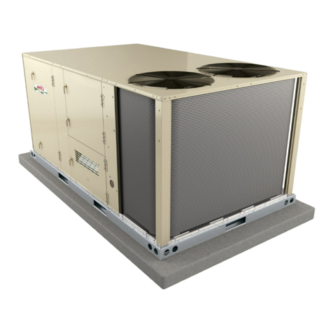
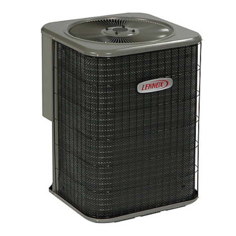
  9. Lennox 10GCS-024 User manual

Lennox 10GCS-024 User manual

This manual suits for next models

11

Other Lennox Air Conditioner manuals

Lennox SL25XPV Series User manual

Lennox

Lennox SL25XPV Series User manual

Lennox 2SCU13-18 User manual

Lennox

Lennox 2SCU13-18 User manual

Lennox KGA092KGA102KGA120KGA150 User manual

Lennox

Lennox KGA092KGA102KGA120KGA150 User manual

Lennox XC21 User manual

Lennox

Lennox XC21 User manual

Lennox CH35 Series User manual

Lennox

Lennox CH35 Series User manual

Lennox Elite XC14-018-230 User manual

Lennox

Lennox Elite XC14-018-230 User manual

Lennox 13ACX User manual

Lennox

Lennox 13ACX User manual

Lennox 15GCSX Series Guide

Lennox

Lennox 15GCSX Series Guide

Lennox 13ACX Manual

Lennox

Lennox 13ACX Manual

Lennox MHA Series User manual

Lennox

Lennox MHA Series User manual

Lennox Baltic BCK 020 User manual

Lennox

Lennox Baltic BCK 020 User manual

Lennox Relax series User manual

Lennox

Lennox Relax series User manual

Lennox MMA018SM4 User manual

Lennox

Lennox MMA018SM4 User manual

Lennox LGH 036 User manual

Lennox

Lennox LGH 036 User manual

Lennox XP14-018-230-06 Operating instructions

Lennox

Lennox XP14-018-230-06 Operating instructions

Lennox SSB036H4S4 User manual

Lennox

Lennox SSB036H4S4 User manual

Lennox DAVE LENNOX SIGNATURE G71MPP-36B-070 User manual

Lennox

Lennox DAVE LENNOX SIGNATURE G71MPP-36B-070 User manual

Lennox GCS26 Series Guide

Lennox

Lennox GCS26 Series Guide

Lennox Comfair HD Series User guide

Lennox

Lennox Comfair HD Series User guide

Lennox LICH4024180P431-C User manual

Lennox

Lennox LICH4024180P431-C User manual

Lennox MHA Series User manual

Lennox

Lennox MHA Series User manual

Lennox AIRCOOLAIR User manual

Lennox

Lennox AIRCOOLAIR User manual

Lennox COMFORT User manual

Lennox

Lennox COMFORT User manual

Lennox VRF V22B Series User manual

Lennox

Lennox VRF V22B Series User manual

Popular Air Conditioner manuals by other brands

Fujitsu ASYG 09 LLCA installation manual

Fujitsu

Fujitsu ASYG 09 LLCA installation manual

York HVHC 07-12DS Installation & owner's manual

York

York HVHC 07-12DS Installation & owner's manual

Carrier Fan Coil 42B Installation, operation and maintenance manual

Carrier

Carrier Fan Coil 42B Installation, operation and maintenance manual

intensity IDUFCI60KC-3 installation manual

intensity

intensity IDUFCI60KC-3 installation manual

Frigidaire FAC064K7A2 Factory parts catalog

Frigidaire

Frigidaire FAC064K7A2 Factory parts catalog

Sanyo KS2432 instruction manual

Sanyo

Sanyo KS2432 instruction manual

LG MultiV Series installation manual

LG

LG MultiV Series installation manual

CLIMAVENETA a-CHD U-2T 606+2209 OPERATING AND INSTALLATION Manual

CLIMAVENETA

CLIMAVENETA a-CHD U-2T 606+2209 OPERATING AND INSTALLATION Manual

Midea EWK06CW5 user manual

Midea

Midea EWK06CW5 user manual

Pioneer FAB Series installation manual

Pioneer

Pioneer FAB Series installation manual

SPT WA-1511S user manual

SPT

SPT WA-1511S user manual

Mitsubishi Electric Mr.Slim MSZ-A24NA operating instructions

Mitsubishi Electric

Mitsubishi Electric Mr.Slim MSZ-A24NA operating instructions

Mitsubishi Electric PUHZ-RP50VHA4 Service manual

Mitsubishi Electric

Mitsubishi Electric PUHZ-RP50VHA4 Service manual

Panasonic CS-S18HKQ Service manual

Panasonic

Panasonic CS-S18HKQ Service manual

Panasonic CS-E15NKE3 operating instructions

Panasonic

Panasonic CS-E15NKE3 operating instructions

Gree GWH18TC-K3DNA1B/I Service manual

Gree

Gree GWH18TC-K3DNA1B/I Service manual

Friedrich ZoneAire Compact P08SA owner's manual

Friedrich

Friedrich ZoneAire Compact P08SA owner's manual

Daikin R32 Split Series installation manual

Daikin

Daikin R32 Split Series installation manual

manuals.online logo
manuals.online logoBrands
  • About & Mission
  • Contact us
  • Privacy Policy
  • Terms and Conditions

Copyright 2025 Manuals.Online. All Rights Reserved.

LENNDX
,1,_2000Lennox industries Inc
Daltas, Texas, USA
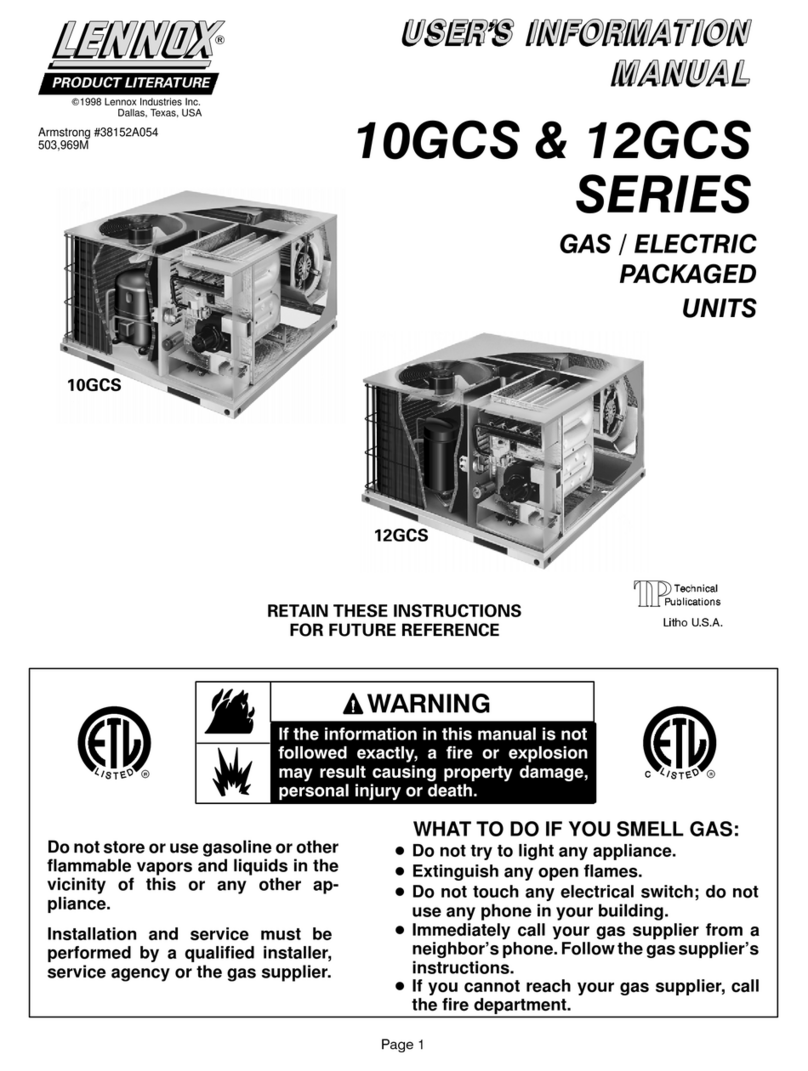
10GCS
12GCS
RETAIN THESE INSTRUCTIONS
FOR FUTURE REFERENCE
INSTALLATION
INSTRUCTIONS
10GCS & 12GCS
SERIES UNITS
GAS PACKAGED UNITS (2-5 TONS)
Armstrong # 38152A058
504,245M
08/03
Supersedes 05/00
_pu Technical
blications
Litho U.S.A.
Unit Dimensions ................................ 2
Parts Arrangement ............................. 4
Shipping & Packing List ......................... 4
General ....................................... 4
Requirements .................................. 4
Clearances .................................... 5
Rigging & Setting Unit ........................... 5
Condensate Drain .............................. 6
Filters ......................................... 6
Supply & Return Connections .................... 6
Installing Vent Hood ............................. 6
Combustion Discharge .......................... 6
Compressors .................................. 7
Gas Piping .................................... 7
LPG/Propane Units, Tanks, & Piping .............. 8
Electrical ...................................... 8
Sequence of Operation ......................... 11
Condenser Fan Clearances ..................... 12
Start-up Check List ............................ 13
Heating Start-up ............................... 13
Burner Adjustments ............................ 14
Manifold Gas Pressure Adjustment ............... 14
High Altitude Information ....................... 14
Unit Controls .................................. 14
Maintenance .................................. 15
Troubleshooting ............................... 15
Led Codes & Flash Rates ....................... 16
Repair Parts & Accessories ..................... 16
j -&WARNING
Do not store or use gasoline or other
flammable vapors and liquids in the
vicinity of this or any other ap-
pliance.
Installation and service must be
performed by a qualified installer,
service agency or the gas supplier.
08/03
IIIIIIIIIIIIIIIIIIIIIIIIIIIIIIIIIIIIIIII
WHAT TO DO IF YOU SMELL GAS:
• Do not try to light any appliance.
•Extinguish any open flames.
•Do not touch any electrical switch; do not
use any phone in your building.
•Immediately call your gas supplier from a
neighbor's phone. Follow the gas supplier's
instructions.
•If you cannot reach your gas supplier, call
the fire department.
504,245M
IIIllllllllllllllllllllllllllllllHlllllllll
Page 1
Model
Number
t0GCS-024
t0GCS-030
t0GCS-036
10GCS-042
10GCS-048
10GCS-O6O
Corner Weights -- Ibs. (kg)
AA BB CC DD
Ibs, kg Ibs. kg Ibs, kg Ibs. kg
75 34 67 30 68 3t 9t 4t
77 35 69 3t 70 32 95 43
84 38 76 34 77 35 t03 47
92 42 83 38 83 38 t12 5t
tt2 5t t01 46 t01 46 t36 62
116 53 106 48 106 48 142 64
EVAPORATOR _
COIL
BLOWER
Center of Gravity -- inches (mm)
Model EE
Number inch mm
t OGCS-024 2t -1/2 546
t OGCS-03O 21-1/2 546
t OGCS-036 2t -1/2 546
t OGCS-042 21-1/2 546
t OGCS-048 23-3/8 594
1OGCS-O6O 23-3/8 594
G G
AA
inch
25
25
25
25
30-t/8
30-1/8
BB
FF mm
635
635
635
635
5tt
511
HEAT
EXCHANGER
CONDENSER
COIL I_
INTAKE
AIR
CONDENSER
COIL FAN
CONDENSER
COIL
.9.
CONDENSER COIL
INTAKE AIR
TOP VIEW
CONDENSER COIL
EXHAUST AIR
FORKLIFT
SLOTS
(Front and
Back Only)
BASE RAIL
FILTER /
RACK
CONDENSATE
DRAIN
4-5/8 _
BASERAIL
Q
4-7/8
(124)
_i rI-REFRIGE RANT
SERVICE
PORTS
FLUE
OUTLET
4
FRONT VIEW
C
CONDENSER COIL_h,
EXHAUST AIR m
(117) ____ _ R BASE RAIL _!
LEFT SIDE
-(
A
2 -7/16
(62)
J
GAS
INLET
DD
M M
BACK VIEW
C
BASE RAIL
ELECTRICAL COMBUSTION AIR
INLETS INDUCER BASE RAIL
RIGHT SIDE
Model A B C D E F G H
Number inch mm inch mm inch mm inch mm inch mm inch mm inch mm inch mm
10GCS-024 t 30t 36 27-11/16 703 45-5/8 1159 45-5/8 1159 25-1/4 641 1-13/16 46 4 102 1-7/8 48 17-15/16 456
10GCS-042 3t-11/16 805 45-5/8 1159 45-5/8 1159 29-1/4 743 1-13/16 46 4 102 1-7/8 48 19-15/16 506
10GCS-048,060 33-11/16 856 54-11/16 1389 49-5/8 1260 3t-7/16 799 1-1/8 29 6-1/8 159 2-1/4 57 19-15/16 506
Model J KL M N P Q R
Number inch mm inch mm inch mm inch mm inch mm inch mm inch mm inch mm
10GCS-024 t 30 t 36 2-1/4 57 15-5/8 397 11-1/2 292 17-1/2 445 5 127 4 102 46-3/8 1179 46-3/8 1179
10GCS-042 2-1/4 57 t5-5/8 397 tt-1/2 292 t7-t/2 445 5 t27 4 t02 46-3/8 tt79 46-3/8 t179
10GCS-048, 60 3-1/2 89 17-1/8 435 12 305 2t-1/2 527 4-1/8 105 5-5/8 143 55-1/4 1403 50-1/2 1283
Page 2
Model
Number
12GCS-024
12GCS-030
t2GCS-036
t2GCS-042
12GCS-048, -060
Corner Wei_ hts -- Ibs.
AA BB ''CC DD
Ibs, kg Ibs, kg Ibs, kg Ibs, kg
80 36 69 3t 73 33 99 45
82 37 71 32 75 34 103 47
89 40 78 35 82 37 tll 50
97 44 89 40 88 40 t30 59
117 53 103 47 106 48 144 65
Center of Gravity -- inches (mm)
EE
Model
Number inch mm inch
t2GCS-024 2t 533 25-t/2
t2GCS-030 2t 533 25-t/2
12GCS-036 2t 533 25-1/2
t2GCS-042 2t 533 25-t/2
t2GCS-048, -060 22-3/4 578 30-1/2
FF
mm
648
648
648
648
775
EVAPORATOR /
COIL
CONDENSER
COIL _D
INTAKE
AIR
/
CONDENSER
COILFAN /
CONDENSER
COIL
FORKLIFT
SLOTS
(Front and
Back Only)
BASE RAIL
FILTER
RACK
DRAIN
:_ BLOWER
J
m
i :!i
i
i :!
!
/'_ CONDENSER COIL
INTAKE AI R
TOP VIEW 4-7/8
B r_11241_-R
tCONDENSER COIL
EXHAUST AIR EFRIGERANT
SERVICE
PORTS
HEAT
j EXCHANGER
3
FLUE
OUTLET
AA G
DD
E-ID
BB
E
EE
1
FF "_4 CC
TOP VIEW BASE SECTION
B _--
QBASE RAIL _---I _ M'_I FI_ M "_P
FRONT VIEW BACK VIEW
C = = C
CONDENSER COIL,_IL
EXHAUST AIR II
J
GAS
I BASE RAIL
R ELECTRICAL COMBUSTION AIR
LEFT SIDE INLETS RIGHTINDUCERSIDE BASERAIL
L
V
[(51) A
\ BASE RAIL
Model A B C D E F G H
Number inch mm inch mm inch mm inch mm inch mm inch mm inch mm inch mm
12GCS-024, 30, 36 27-11/16 703 45-5/8 1159 45-5/8 1159 25-1/4 641 1-13/16 46 4 102 1-7/8 48 17-15/16 456
12GCS-042 3t-tl/16 805 45-5/8 tt59 45-5/8 tt59 29-t/4 743 t-13/16 46 4 t02 t-7/8 48 t9-t5/t6 506
12GCS-048, 060 33-tl/16 856 54-tl/16 t389 49-5/8 t260 3t-7/16 799 t-1/8 29 6-t/8 t59 2-1/4 57 t9-t5/t6 506
JK L M NP Q R
Model
Number inch mm inch mm inch mm inch mm inch mm inch mm inch mm inch mm
12GCS-024, 30, 36 2-1/4 57 15-5/8 397 11-1/2 292 17-1/2 445 5 127 4 102 46-3/8 1179 46-3/8 1179
12GCS-042 2-1/4 57 15-5/8 397 11-1/2 292 17-1/2 445 5 127 4 102 46-3/8 1179 46-3/8 1179
12GCS-048, 060 3-1/2 89 17-1/8 435 12 305 21-1/2 527 4-1/8 105 5-5/8 143 55-1/4 1403 50-1/2 1283
Page 3
condenserfan
condensercoil
blower motor
compressor
pressure switch
gas
manifold
gas valve
combustion
air inducer
burner box
control box section
heatexchanger
assembly
Figure 1
1 - Assembled gas package unit
1 - Vent hood assembly with screen and screws
As soon as the unit is received, it should be inspected for
possible damage during transit. If damage is evident, the
extent of the damage should be noted on the carrier's
freight bill.A separate request for inspection by the carrier's
agent should be made in writing.
These installation instructions are intended as a general
guide only, for use by an experienced, qualified contractor.
The 10GCS and 12CGS units are single-package air
conditioners with gas heat designed for outdoor installation
on a rooftop or a slab.
The units are completely assembled. All piping, refrigerant
charge, and electrical wiring are factory installed and
tested. The units require only electric power, gas piping,
condensate drain and duct connections plus assembly of
heating rain hood at the point of installation.
NOTE -These units must not be used as a construction
heater at any time during any phase of construction.
Very low return air temperatures, harmful vapors, and
misplacement of the filters will damage the unit and its
efficiency.
WARNING
Page 4
WARNING
These units are design certified by E.T.L and E.T.L
Canada as follows:
1 - For use as a forced air furnace with cooling unit.
2 - For outdoor installation only.
3 - For installation on combustible material.
4 - For use with natural gas or propane gas.
Not suitable for use with conventional venting systems
These units must be installed in accordance with the
following national and local safety codes.
1 - National Electrical Code ANSI/NFPA No. 70 latest edi-
tion (U.S.A.).
2 - Local gas utility requirements. In the absence of local
gas codes the National Fuel Gas Code ANSI Z223.1
latest edition should be used. (U.S.A.)
3 - Canadian Electrical Code C22.1 Part 1 (latest edition).
4- Canadian Installation Codes CAN/CGA-B149.1 & .2
(latest edition).
If components are to be added to a unit to meet local codes,
they are to be installed at the dealer's and/or customer's
expense.
Service Clearances for Units
Top Clearance Unobstructed
Bottom Clearance Is 10 In.
right
ill
12 in.
*Rear clearance is 36 in. with or 2 in. without an economizer.
Figure 2
In the U.S. units may be installed on combustible floors
made from wood or class A, B, or C roof covering material.
In Canada, units may be installed on combustible floors.
Units must be installed outdoors. Overhanging structures
or shrubs should not obstruct condenser air discharge
outlet.
Use the following guidelines to select a suitable location for
these units.
Exercise care when moving the unit. Do not remove any
packaging until the unit is near the place of installation. A
sling assembly may be used to lift unit. Spreaders whose
length exceeds the largest dimension across the unit
MUST be used across the top of the unit.
Ak CAUTION
All units require certain clearances for proper operation
and service. Refer to figure 2 for the clearances required
for combustible construction, servicing, and proper unit
operation.
When installed at ground level, this unit must be used with
the 4-inch lift kit or other applicable means to raise the
bottom of the flue hood to 12 inches above ground to meet
the snow requirements. See Combustion Discharge
section. Clearance to combustibles below unit is 10 inches
since the flue points down.
NOTE -Do not permit overhanging structures or shrubs to
obstruct condenser air discharge outlet, combustion air in-
let or vent outlet.
Units may also be moved or lifted with a forklift while still in
the factory supplied packaging.
NOTE -Length of forks must be a minimum of 42 inches.
1 - Unit is designed for outdoor installation only. Unit must
be installed so all electrical components are protected
from water.
2 - Condenser coils must have an unlimited supply of air.
3 - For ground level installation, use a level pre-fabricated
pad or use a level concrete slab with a minimum thick-
ness of 4 inches. The length and width should be at
least 6 inches greater than the unit base. Do not tie the
slab to the building foundation.
4 - Maintain level within a tolerance of 1/4 inch maximum
across the entire length or width of the unit.
Page 5
Thepackagedunitisequippedwitha3/4inchfptcoupling
forcondensatelineconnection.Plumbingmustconformto
localcodes.Use a sealingcompoundon malepipe
threads.
Thedrainlinemustbeproperlytrappedandroutedtoa
suitabledrain.Seefigure3forproperdrainarrangement.
Thedrainlinemustpitchto anopendrainor pumpa
minimumof 1inchper10feetto preventcloggingofthe
line.Sealarounddrainconnectionwithsuitablematerialto
preventairleakageintoreturnairsystem.
Drainpipingshouldnotbesmallerthandrainconnectionat
coil.Anopenventindrainlinewillsometimesberequired
dueto linelength,frictionandstaticpressure.Drains
shouldbeconstructedinamannertofacilitatefutureclean-
ing.
NOTE -The condensate drain fine MUST be trapped to
provide proper drainage.
Duct system should be designed and sized according to
the methods in Manual Q of the Air Conditioning
Contractors of America (ACCA).
A closed return duct system shall be used. This shall not
preclude use of economizers or outdoor fresh air intake. It
is recommended that supply and return duct connections
at the unit be made with flexible joints.
The supply and return air duct systems should be designed
for the CFM and static requirements of the job. They
should NOT be sized to match the dimensions of the
duct connections on the unit,
Ak CAUTION
Typical Condensate Drain
Minimum Pitch
1in. (25 ram) per
10' (3 m) of line
open
vent
unit
,%
Trap must be deep enough to offset maximum mounting
static difference (Generally, 3 inches minimum), frame
Figure 3
The vent hood is installed by placing screen in hood and
securing with four #8 x 3/8 large blunt sheet metal screws
and four #8 flat speed nuts as shown in figure 4. Place hood
with screen in position and attach with three #8 x 1/2 sheet
metal screws using holes provided.
Vent Hood Installation
o
HOOD 1
screen
No filters are supplied with the unit. Filters must always be
installed ahead of evaporator coil and must be kept clean or
replaced. Dirty filters will reduce the airflow of the unit.
Filters sizes are shown in table 1.
Unit is equipped with an internal filter clip which is located in
indoor coil compartment attached to side of the unit drain
pan. Table 1
Unit Filter Size
Unit Model Filter Size
-024, -030, -036 24 in. X 25 in.
-042 28 in. X 25 in.
-048 -060 30 in. X 30 in.
Figure 4
The products of combustion are discharged horizontally
through a screened opening on the gas heat side panel.
The horizontal vent system shall terminate at least 4 feet
below, 4 feet horizontally from, or 1 foot above any door,
window, or gravity air inlet into the building. The vent
system shall terminate at least 3 feet above any forced air
inlet located within 10 feet. The bottom of the vent
terminal shall be located at least 12 inches above grade.
Minimum horizontal clearance of 4 feet from electric
meters, gas meters, regulators, and relief equipment is
required.
Page 6
Theventoutletmustbeinstalledinalocationthatprevents
buildingdegradationandmustbe consistentwith the
NationalFuelGasCode,Z223.1orCAN/CGA-B149,1&.2,
In addition to the above requirements, consideration must
be given to prevent unwanted ice build-up from the vent
condensate. The vent should not be located on the side of a
building where the prevailing winter winds could trap the
moisture causing it to freeze on the walls or on overhangs
(under eaves), The vent location should not discharge over
a sidewalk, patio or other walkway, where the condensate
could cause the surface to become slippery,
The products of combustion must not be allowed to
accumulate within a confined space and recirculate,
Units are shipped with the compressor mountings
factory-adjusted and ready for operation.
Proper sizing of gas piping depends on the cubic feet per
hour of gas flow required, specific gravity of the gas and
length of run, The current National Fuel Gas Code Z223,1
should be followed in all cases unless superseded by local
codes or gas company requirements, Refer to tables 2 and
3, In Canada see CAN/CGA B,149,1 & ,2 (latest edition),
Table 2
Gas Heat Application Data
Input Rating Output Rating Gas Capaci_
(Btu) (Btu) (FT3 /HR)
50,000 40,000 47
75,000 60,000 70
100,000 80,000 93
125,000 100,000 116
Before connecting piping, check with gas company or
authorities having jurisdiction for local codes or require-
ments. When installing gas supply piping, length of run
from gas meter must be considered in determining pipe
size for 0,5 inch w.c, maximum pressure drop. Do not
use supply pipe smaller than unit gas connection, For
natural gas unit, operating pressure at the unit gas con-
nection must be a minimum of 4.5 inch w.c. and a maxi-
mum of 13,5 w.c. For propane/LP gas units, operating
pressure at the unit gas connection must be a minimum
of 11 inches w.c. and a maximum of 13,5 inches w.c,
Table 3
Gas Pipe Capacity-FT 3 /HR
Nominal Iron Pipe Size (inches)
Length in Feet 1_ in.
10 132
20 92
30 73
40 63
50 56
60 50
70 46
80 43
90 40
100 38
3/4 in. 1in. 1-1/4 in.
278 520 1050
190 350 730
152 285 590
130 245 500
115 215 440
105 195 400
96 180 370
90 170 350
84 160 320
79 150 305
When making piping connections, a drip leg should be
installed on vertical runs to serve as a trap for sediment or
condensate, A 1/8 inch N,RT. tap accessible for test gauge
connection must be provided in field piping upstream from
gas supply connection to unit. Install a ground joint union
between gas control manifold and the manual main shut-
off valve. See figure 5,
Compounds used on threaded joints of gas piping shall be
resistant to the action of propane/LP gases.
Drip Leg Installation
field provided
1/8 in. p
ground joint
union
manual main
shut-off
base of unit
leg support
piping
support
Figure 5
Pressure Test Gas Piping
When pressure testing gas lines, the gas valve must be dis-
connected and isolated. Gas valve can be damaged if sub-
jected to more than 0,5 psig (14 inch w.c.), See figure 6,
If test pressure is equal to or less than 0,5 psig (14 inch
w.c.) shutoff the manual main shut-off valve before pres-
sure testing to isolate unit from gas supply system.
Page 7
Isolate Gas Valve To Pressure Test
Manual Main Shut-off Valve Will Not Hold Test
Pressures in Excess of 0.5 PSIG (14 in. w.c.)
unit
gas valve cap
Fiaure 6
NOTE -Codes may require that manual main shut off valve
and union (furnished by installer) be installed in gas line exter-
nal to unit. Union must be of the ground joint type.
,WARNING
After gas piping is complete, carefully check all piping con-
nections (factory and field) for gas leaks, Use soap solution
or other preferred means.
NOTE -In case of emergency shutdown, shut off main
manual gas valve and disconnect main power to unit.
These devices should be properly labeled by installer.
The heating value of the gas may differ with locality, The
value should be checked with the local gas utility.
NQ TE -Units are shipped equipped for natural gas, but can
be converted to LPG/propane with a conversion kit.
NOTE- There may be a local gas utility requirement speci-
fying a minimum diameter for gas piping. All units require a
1/2 inch pipe connection at the gas valve.
Gas piping recommendations:
1 - A drip leg and a ground joint union must be installed in
the gas piping.
A ground joint union is recommended by the man-
ifold/valve,
2 - When required by local codes, a manual shut-off valve
may have to be installed outside of the unit,
3 - Use pipe thread sealing compound resistant to pro-
pane gas sparingly on male threads,
4 - The gas supply should be a separate line and installed
in accordance with all safety codes. After the gas con-
nections have been completed, open the main shut-off
valve admitting normal gas pressure to the mains,
Check all joints for leaks with soap solution or other
material suitable for the purpose,
Ak CAUTION
5 - The furnace and its individual manual shut-off valve
must be disconnected from the gas supply piping sys-
tem during any pressure testing of that system at test
pressures in excess of 1/2 PSIG (3,48kPa),
AkIMPORTANT
6 - A 1/8 inch N.ET. plugged tapping, accessible for test
gage connections, must be installed immediately up-
stream of the gas supply connection to the furnace,
Check the unit rating plate for type of gas that unit is
equipped for. If conversion is required use the approved
conversion kit, The unit may be converted in the field for
use with LPG/propane gas with accessory kit by an
approved licensed pipe fitter or technician,
All LPG/propane gas equipment must conform to the safety
standards of the National Fire Protection Association.
For satisfactory operation, LPG/propane gas pressure must
be a minimum of 11 inches W.C, at the unit under full load,
Complete information regarding tank sizing for
vaporization, recommended regulator settings, and pipe
sizing is available from most regulator manufacturers and
LPG/propane gas suppliers,
Check all connection for leaks when piping is completed,
using a soapy solution,
ALL WIRING SHOULD BE DONE IN ACCORDANCE
WITH NATIONAL ELECTRIC CODE, ANSI/NFPA No. 70
(LATEST EDITION), IN CANADA CSA C22.2 Part 1
(LATEST EDITION), OR WITH LOCAL CODES, WHERE
THEY PREVAIL.
Page 8
CO "4
10GCS Series Gas Packaged Units
LI
UNIT HEATING COOLING
SPEED SPEED
IOGCSO24-50 MEDIUM LOW
IOGCSO24-75 HIGH LOW
IOGCSO3O-5O LOW MEDIUM
IOGCSO30-75 HIGH MEDIUM
EOGCSO36-50 MEDIUM HIGH
IOGCS036-75 HIGH HIGH
IOGCSO3B-IOO HIGH HIGH
IOGCSO¢2-75 HIGH HIGH
IOGCSO42-100 HIGH HIGH
IOGCS048-100 MEDIUM LOW
EOGCSOAB=EB5 HIGH LOW
IOGCS048=I50 HIGH LOW
IOGCS06O-IOO MEDIUM HIGH
EOGCS060-_25 HIGH ÷HIGH
EOGCSOGO-E50 HIGH HIGH
B3
BLOWER
MOTOR
Typical Wiring Diagram
BA
CONDENSER
FAN MOTOR
510
AUTO RESET
LIMIT SWITCH
C12 518
DUAL CAPACITOR PRESSURE
BG SWITCH
GOMBOSTIONAIR
BLOWER
KI-I
COMPRESSOR
CONTACTOR
C12
DUAL
BK
B_
COMPRESSOR
B_
COMPRESSOR RD
KI-2
COMPRESSOR
CONTACTOR
L2
B
CONDENSER
FAN MOTOR
•JUMPER REQUIRED
IF JUMPER IS NOT USED,
CONNECT BLUE WIRE ON UNUSEO
TERMINAL TO HEAT.
NOTE-IF ANY WIRE IN THIS APPLIANCE IS REPLACED, IT
MUST BE REPLACED WITH WIRE OF LIKE SIZE, RATING
AND INSULATION THICKNESS.
Z_ USE JUMPER ONLY IF HEAT AND COOL
ARE THE SAME SPEED.
Z_ B6 (CAB) IS ENERGIZED FOR IO SECONDS
AT THE START OF EACH COOLING CYCLE
VT
COMBUSTIOI
GN
A3
$47
MANUAL RESET
ROLLOUTGWITCH ELECTRIC/SENSOR
GVI C4
S21 GAS BLOWER MOTOR
AUTO RESET AUX. VALVE CAPACITOR
LIMIT SWITCH
CONTROL BOX
RGWCY HTG, ACC,
_ CWB'=BLWR
TBI
iD® @
i (_(_ ACB==_OOL
ACB_EAT
GROUND UNUSED
ELECTRODE
BAVAC FLAME @
HOT
A5 BLOWER/IGNITION
CONTROL
TRANsTLRMER[
I :
CONTACTOR
BLUE(C)
YELLOW(Y)
RED(R)
GREEN(G)_
WHITE(W_
SI
THERMOSTAT
I I I i
)- J I I I
I
_---J I I
_ COMPRES50_
T_ _CONTACTOR_
USE WITH COPPER
CONDUCTORS ONLY
MINIMUM 75°C WIRE
DISCONNECT ALL POWER
BEFORE SERVICING
-- LI 208-230/60/I
L2
SI
"_ THERMOSTAT
--'111 jl _.1 J
HEAT ANTICIPATION SETTING- 0.75
LINE VOLTAGE FIELD INSTALLED
2,$ VOLT FIELD INSTALLED
NEC/CEC CLASS 2
NOTE-ALL REMAINING WIRES
FACTORY INSTALLED
LENNOXz#_,,,J,_[_. WIRING DIAGRAM
COMBINATION UNITS-ROOFTOP
I 0GC5024-50,75-2, -3-P
I OGCS030-50,75-2, -3-P
10605056-50,75, 100-2, 5-P
I 0GC5042-75, 100-2, -$-P
IOGCS048-100 125, 150-2,-5-P
IOGCSOBO-IO0 IZ5,150-2, -3-P
Supersedes Form No, _ New Form No.
555,466W ]534,449WLi_ho U.S,A.
-o _"n..
O0
12GCS Series Gas Packaged Units
Typical Wiring Diagram
HEATING COOLING
UNIT SPEED SPEED
12GCS024=50 MEDIUM LOW
12GCS024-75 HIGH LOW
12GCSOSO-50 MEDIUM* MEDIUM
12GC5030-75 HIGH MEDIUM
IZGCSO36-50 MEDIUM HIGH
i2GCS036-75 HIGH *HIGH
i2GCSO3S=IOO HIGH HIGH
12GCS042-75 HIGH HIGH
12GCSO42-100 HIGH ÷ HIGH
12GCSO¢8=IOO MEDIUM* MEDIUM
12GC5048-125 HIGH MEDIUM
12GCSOEO-IO0 MEDIUM HIGH
E2GCSO60=125 HIGH HIGH
?
83
BLOWER
MOTOR
B4
CONDENSER
FAN MOTOR
S_O
AUTO RESET
LIMIT SWITCH
(_) CI2 $18 $21
DUAL CAPACITOR PRESSURE AUTO RESET AUX,
SWITCH LIMIT SWITCH
COMBUSTION
AIR
BLOWER
Bl
COMPRESSOR
* JUMPER REQUIRED
IF JUMPER IS NOT USED,
CONNECT BLUE WIRE ON UNUSED
TERMINAL TO HEAT.
NOTE-IF ANY WIRE IN THIS APPLIANCE IS REPLACED, IT
MUST BE REPLACED WITH WIRE OF LIKE SIZE, RATING
AND INSULATION THICKNESS.
Z_ USE JUMPER ONLY IF HEAT AND COOL
ARE THE SAME SPEED,
/2_ B6 (CAB) IS ENERGIZED FOR IO SECONDS
AT THE START OF EACH COOLING CYCLE
KI-E
COMPRESSOR
CONTACTOR
C12
DUAL
K2
COMPRESSOR RD
KE-2
COMPRESSOR
CONTACTOR
L2
BA
CONDENSER
FAN MOTOR
CAPACITOR T
COMBUSTIO#
AIR BLOWER
$47
[_ MANUAL RESET
ROLLOUTSWITCH ELECTRIC/SENSOR
GVI C_
GAS BLOWER MOTOR
VALVE CAPACITOR
A3
BLOWER/IGNITION
CONTROL
R G W C Y HTG, ACC.
CWB LWR
TBI _
ACB'=_OOL
ACB=HEAT
GROUND UN'_SED
ELECTRODE
B4VAC FLAME @
_HOT
CONTROL BOX
DL8
TIMED
OELAY
RELAY
TRANSFORMER
Ki
CONTACTOR
BLUE
YE_LLO_ Q'"
RED(R_
GREEN(G_
WHITE(W)
A3
DISCONNECT ALL POWER
BEFORE SERVICING
208-230/60/I
L2
USE WITH COPPER
CONDUCTORS ONLY
MINIMUM 75°C WIRE
_E. SI
THERMOSTAT
--'jII JI_1 d
HEAT ANTICIPATION SETTING- 0,75
LINE VOLTAGE FIELD INSTALLED
24 VOLT FIELD INSTALLED
NEC/CEC CLASS 2
NOTE-ALL REMAINING WIRES
FACTORY INSTALLED
I_ENNDX_ ......._oo.WIRINGDIAGRAMo4LO_
COMBINATION UNITS-ROOFTOP
I 2GC5024-50,75-2, -3-P
12GCS03O-50,75-2, -3-P
12GCSO36-50,75, 100-2, -3-P
12GCS042-75, 100-2, -3-P
12GCSO48- IDO, 125-2, -3, -A-P
12GCSOBO- IOO, 125-2, -3, -A-P
Supersede_ Form No. I New Form No-
533,467W ] 534,450W
Lithe U.S,A.