manuals.online logo
Brands
  1. Home
  2. •
  3. Brands
  4. •
  5. Lennox
  6. •
  7. Air Conditioner
  8. •
  9. Lennox UNICO User manual

Lennox UNICO User manual

TECHNICAL
MANUAL
2
3
INDEX
Page
1 Presentation 3
2 Fundamental concepts 3
2.1 Heat and temperature 3
2.1.1 Heat 4
2.1.2 Temperature 4
2.2 Transmission of heat 5
2.3 Pressure 6
3 Rapid calculation of building load factors 6
3.1 Calculation of summer re-entry 7
3.2 Calculation of winter dispersion 8
4 Principles of refrigeration 9
4.1 The refrigeration cycle 9
4.2 The components of the refrigeration circuit 10
4.3 Refrigeration circuits of devices 11
4.3.1 Refrigeration circuit diagram of UNICO
models for cooling only 11
4.3.2 Refrigeration circuit diagram of UNICO
models with heat pump 11
5 Operations on refrigeration circuits 13
6 Execution of joints in refrigeration circuit 13
6.1 Welding 13
7 Replacement of refrigeration compressor 13
8 Creation of a vacuum in the refrigeration
circuit 14
9 Filling with coolant 14
10 Operating logic 15
10.1 Power supply to unit 15
10.2 Switching on and control of unit 15
10.3 Cooling program 15
10.4 Air recycling program (fan) 16
10.5 Dehumidifying program 16
10.6 Program for night operation 16
10.7 Program of “air change” 16
10.8 General automatic program 16
10.9 Heating with heat pump 16
10.10 Programming timer and schedule 17
10.11 Operation of the system for disposal
of condensate in cooling mode 17
11 Alarm signals 18
11.1 Tests of operation and diagnosis
of possible malfunctions 18
12 Analysis of possible solutions
to prevent alarm situations 19
13 Wiring diagrams 23
14 Measurements 24
15 Assembly template 25
1 Presentation
Thismanualhasbeenwrittenforthedualpurposeofproviding
an easy, comprehensive text for people who are interested
in knowing more about our “UNICO” air conditioning system,
andausefulguidetomaintenanceandrepairoftheequipment
for professional installers and service centers.
We therefore recommend careful reading both for those
interested in undertaking an activity of installation or after
sales service of our air-conditioners and those who just want
to know more about the technology of this sector.
Any suggestions will be welcome and we will certainly take
them into serious consideration in drawing up future editions
of this manual.
2 Fundamental concepts
This chapter will illustrate the basic concepts which must be
thoroughly clear to anyone operating in this sector.
For reasons of simplicity we have not gone into concepts
that are not strictly concerned with the purposes of this
manual.Theyarecoveredinanytextbookofphysics, for those
who are interested.
Since in the sector of air conditioning the new system of
measurement called SI is still not commonly used, as the old
technical system and even the anglosaxon system still
survive, we have defined all the units of measurements in all
three systems, indicating the equivalence between one and
the others.
Reading this chapter will be rather interesting for beginners,
whilethosewho already have a solid background in the sector
may find explanations, that we hope are clear, for concepts
they have tended to take for granted.
2.1 Heat and temperature
People generally tend to confuse these two concepts that
serve to quantify, or better to measure thermal energy.
In other words, when we speak of heat we mean the amount
of thermal energy, and when we speak of temperature we
mean the potential of that thermal energy. All this has close
analogies with electrical phenomena. Effectively, heat is like
the electrical charge, while temperature is like the difference
of potential that we also call voltage.
The same way, heat flow (that is, the units of thermal energy
that enter and leave a body, a wall, etc., in a specific period
of time) has the same meaning as the electric current which
measures the amount of electric charge that passes in a
specific time period (one second) through a conductor.
4
2.1.1 Heat
Like electrical energy, heat cannot be seen but produces
effects that we perceive with our senses.
In fact, when we heat a body (for example a pot full of water)
we can feel the increase in the temperature of the body. This
form of heat is called perceptible heat.
Heatcan also have other effectsona body. If we keep heating
the pot the temperature of the water in it will continue to rise
until it reaches a saturation temperature that depends on the
pressure applied to the pot.At normal atmospheric pressure,
the saturation temperature of water is 100°C, but if the
pressure on the pot is higher this value rises, as for example
in a pressure cooker where foods cook more rapidly because
the water in them boils at a much higher temperature than
100°C. The opposite occurs at low pressure as, for example,
at high altitudes where water boils at a much lower
temperature than 100°C.
The different in the saturation temperature depends on the
pressure and is common to all liquids.
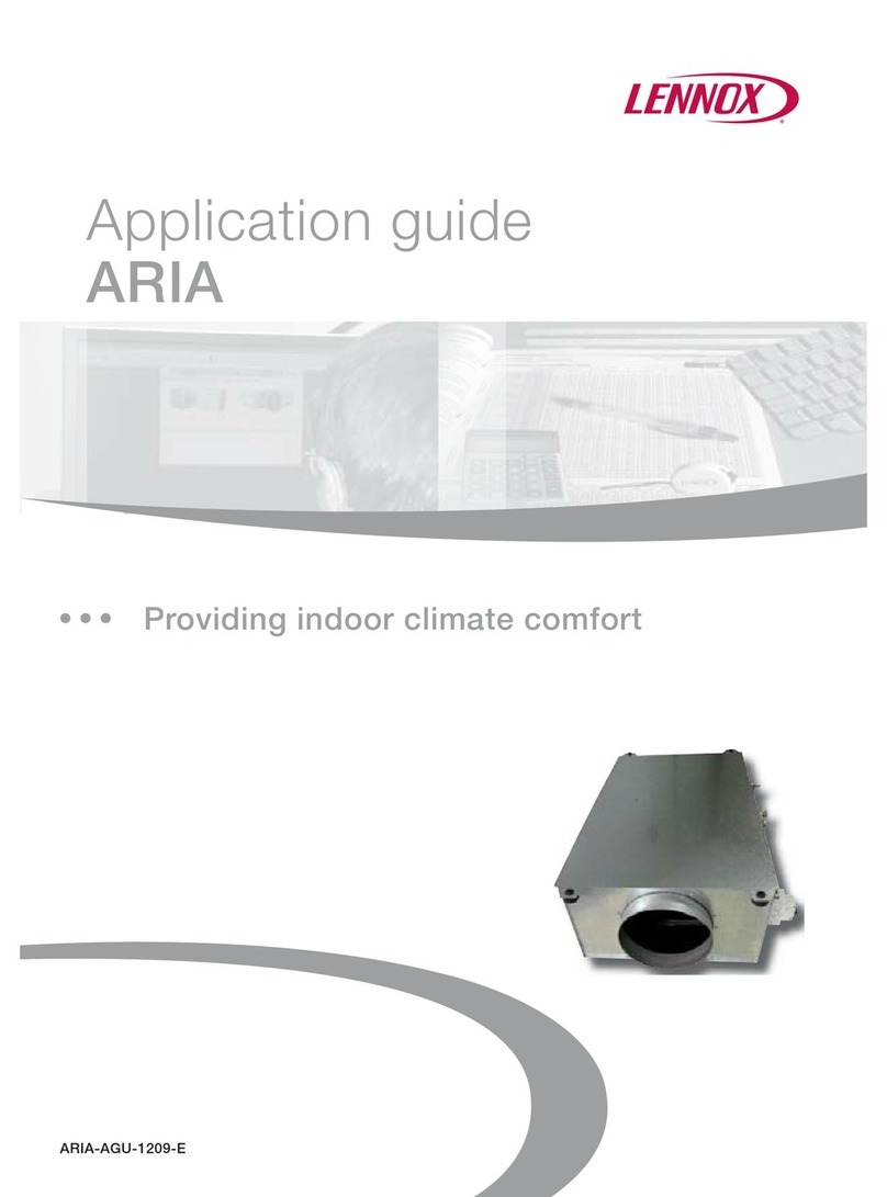
Once it has reached the saturation temperature the liquid
starts to boil and its temperature remains constant. The heat
that causes the evaporation of a liquid is called latent heat.
After all the liquid has boiled, if we continue to apply heat,
the temperature of the steam increases and is superheated
absorbing more perceptible heat.
The same way, if we cool superheated steam (characterized,
therefore, by a temperature higher than that of saturation) it
releases perceptible heat until it reaches the saturation
temperature. When it reaches that temperature it starts to
condense, releasing latent heat to the medium cooling it until
it has all condensed. After the process of condensation, if
cooling continues, the temperature of the liquid falls below
the saturation value and the liquid releases perceptible heat
and is supercooled as a consequence.
The same thing happens if we heat a solid. Gradually, it
reaches a temperature at which it melts. After melting the
temperature of the liquid starts to rise. In this case too, the
phenomenonisreversible, as we can see from freezing water.
Figure 1 diagrams this process for water at atmospheric
pressure.
There are many units of measurement for measuring heat,
but the ones that can interest us in our discussion are:
- kilocalorie(kcal) that is the amount of heat needed to raise
the temperature of 1 kg of water from 15 to 16°C.;
- kilojoule (kJ) that is the amount of heat needed to raise the
temperature of 0.239 kg of water from 15 to 16°C. The kJ
is the unit of measurement of heat used by the SI system
whichis now also compulsory in Italy. One kcal corresponds
to4.187 kJ and therefore onekJ correspondsto 0,239kcal;
- the btu (still used today in anglosaxon countries) that
corresponds to 0,254 kcal (1 kcal therefore corresponds to
3,937btu) or 1,063 kJ (1 kJtherefore correspondsto 0,941
btu).
Heat flow is the amount of heat that transits in a unit of time
through a wall and can be measured in:
- kilocalories per hours (kcal/h);
- Watts(W) thatare simply J per second. OneW corresponds
to 0,86 kcal/h and therefore one kcal/h corresponds to 1,16
W;
- inbtu/h which corresponds to 0,254/h kcal (1 kcal/ therefore
correspond to 3,937 btu) or 0,29 W (1 W therefore
corresponds to 3,5 btu/h).
The last concept that concerns heat measurement is
enthalpy. Enthalpy serves to measure the amount of heat in
a kilogram of a specific substance starting from an arbitrary
zero point. The zero position of reference is unimportant
because more than enthalpy, what interests our calculations
for conditioning and cooling is always the difference of
enthalpy between an initial and a final state.
Enthalpy can be measured in:
-kcal/kg, that are the kilocalories contained in a kilogram of
a specific substance;
-kJ/kg, that are the kilojoules contained in a kilogram of a
specific substance. One kcal/kg corresponds to 4.187 kJ/
kg and therefore one kJ/kg corresponds to 0,239 kcal/kg;
-btu/pound, that are the btu contained in a pound of a
specific substance. One btu/pound corresponds to 0,559
kcal/kgand therefore one kcal/kg corresponds to1,788 btu/
pound. One btu/pound also corresponds to 2,34 kJ/kg and
therefore one kJ/kg corresponds to 0,427 btu/pound.
Measurement of the quantity of heat totally contained in a
body can be obtained by multiplying its enthalpy by its mass
(in kg or in pounds, according to cases).
2.1.2 Temperature
Temperature stands for the potential of heat. In other words,
the higher the temperature of a body, the higher the potential
of the heat that it contains.
A fundamental law of nature (and one that is confirmed to
experience every day by each of us) is that heat passes,
except in case of specific human action, only from bodies
at a higher temperature to bodies at a lower temperature.
To use a mechanical analogy, we can view the transfer of
heatlike the motion of aheavy bodythat, unlesswe intervene
by applying energy, will always move downward.
Both in the technical system in use until a short time ago and
inthenew SI system, temperature is measured on the Celsius
scale (also known as centigrade scale).
The Celsius temperature scale sets an arbitrary zero value
(0°C) at the temperature at which ice melts at atmospheric
pressure and the value of 100 degrees (100°C) at the boiling
point of water at the same pressure. One Celsius degree (°C)
therefore corresponds to one hundredth of the interval
between solidification and boiling of water at atmospheric
pressure.
In anglosaxon countries the temperature scale in use is the
Fig. 1
0
100
t
Somministrazione o
sottrazione di
calore sensibile
Somministrazione o
sottrazione di
calore latente
Somministrazione o
sottrazione di
calore sensibile
Riscaldamento
Sottoraffreddamento
Surriscaldamento
Desurriscaldamento
Ebollizione
Condensazione
Liquido
sottoraffreddato
Cambiamento
di stato
Vapore
surriscaldato
Undercooled
liquid Boiling
Addition or subtraction
of sensitive heat Addition or subtraction
of sensitive heat
Addition or subtraction
of latent heat
Condensation
State
change
Superheated
steam
Heating
Undercooling
Superheating
Desuperheating
5
Fahrenheit scale, that gives the melting point of ice at
atmosphericpressurethe arbitrary value of 32 degrees (32°F)
and assigns a value of 212 degrees (212°F) to the
temperature at which water boils at the same pressure. One
Fahrenheit degree (°F) therefore corresponds to 180th of the
interval between solidification and boiling of water at
atmospheric pressure.
To convert a temperature in °C to the equivalent in °F we
have to use the following formula:
°F = °C x 1,8 + 32
for example, a temperature of 7°C can thus be converted
into a temperature of 7 x 1,8 + 32 = 44,6 °F.
To convert a temperature in °F to the equivalent in °C we
have to use the following formula:
°C = (°F - 32) : 1,8.
In this case, a temperature of 70°F can thus be converted
into a temperature of 70 :1,8 + 32 = 21,11 °C.
Finally, to pass between a difference in °F to a difference in
°C it is sufficient to divide the value in °F by 1,8. The inverse
operation consists of multiplying the value in °F by 1,8.
For greater clarity figure 2 shows the synoptic
correspondence between the Celsius scale and Fahrenheit.
2.2 Heat transmission
As we have already seen, in nature heat passes from a hot
body to a colder one.
There are four ways in which heat is transmitted through
bodies:
-Conduction, that is what happens when we heat one of
the surfaces of the body. The heat that penetrates in the
body is transmitted through it with an ease that varies from
one material to another. In general a good conductor of
electricity is also a good conductor of heat and vice versa.
The thermal conductivity of bodies thus varies depending
on the nature of the bodies and in inverse proportion to
their thickness. Their insulating power (that is the opposite
of conductivity) varies according to the nature of the bodies
and their thickness.
-Convection, that is what happens when, for example, a
wall releases heat into the air at a lower temperature than
the air touching it. The intensity of this phenomenon
depends on the material with which the releasing (or
receiving) wall is made, the roughness of its surface and
the speed of the fluid touching it.
-Radiation, that is what happens when a radiator releases
thepartofheat it receives from a body near but not touching
it (figure 3).
The intensity of radiation varies depending on the nature
of the two bodies exchanging heat, their distance from one
another, their temperature and their heat. In air-conditioning,
the re-entries of heat due to solar radiation have a very
important role as much of the cooling load in a room is due
to solar radiation through windows and to the heating of
the walls due to it. In a glass wall, the radiation that passes
through it can be reduced by the reflecting power of the
glass itself and/or by the presence of screens or curtains.
Radiant heat is measured in W/m2or kcal/(h m2). One W/
m2corresponds to 0,86 kcal/(h m2) and therefore one kcal/
(h m2) corresponds to 1,16 W/m2.
-Adduction isa term that defines heat transmissionthrough
any opaque body (typically, through the walls of a building)
and that consists in part of transmission, in part of radiation
and in part of conduction.
The most important variables regulating adduction are:
- the speed of the fluid (air, in case of a wall) that touches
the inner and outer surface;
- the presence or absence of solar radiation on the outside
and thus the heat of the surface of the wall;
- the temperatures of the air touching the two surfaces of
the wall;
- the nature of the wall, that is, its insulating power.
Adduction is measured in terms of global coefficient of heat
exchange ÒKÓ, which is in kcal/(h m2°C) or in W/(m2°C).
Sometimes the global coefficient of exchange is expressed
in W/(m2K), that have the same physical meaning and same
amplitudeasW/(m2°C).Usually, one W/(m2°C) corresponds
to 0,86 kcal/(h m2°C) and therefore one kcal/(h m2°C)
corresponds to 1,16 W/(m2°C).
2.3 Pressure
As we have said, pressure regulates the level of the boiling
point and condensing temperature. It is therefore important
to have the relative concepts clear since, as we shall see, a
cooling cycle is achieved by boiling a liquid at a low
Fig. 2
100
0
-17,77
°C
212
32
0
°F
Fig. 3
6
temperature and at low pressure and then condensing it at a
higher pressure and temperature.
From a general point of view pressure is the force that is
applied to a unit of surface.
Therefore:
- In the unit of measurement of the old technical system
pressure was measured in atmospheres or kg/cm2.
- In the SI system now in use it is measured in bar
(equivalent to atmospheres or kg/cm2), or in Pa, where
one Pa is a force of one Newton (N) applied to 1 m2(1 kg/
cm2= 1 bar = 100.000 Pa), or also in kilopascal (kPa),
where 1 kPa = 1.000 Pa;
- In the unit of the anglosaxon system the measurement is
in pounds per square inch (PSI). One PSI corresponds to
0,07 bar or atmospheres, while one bar or one atmosphere
corresponds to 14,28 PSI.
There are also two methods for expressing pressure,
regardless of the unit of measurement in which it is measured
(figure 4).
Pressure can also be expressed in:
-absolute terms, considering an absolute vacuum as zero,
-relative terms, considering the atmospheric pressure as
zero,
Thus, to pass from a pressure value expressed in relative
terms (relative pressure) to its equivalent in absolute terms
(absolute pressure) you must:
- increase the value by one if expressed in kg/cm2,
atmospheres or bar;
- increase the value by 100.000 if expressed in Pa;
- increase the value by 100 if expressed in kPa;
- increase the value by 14,7 if expressed in PSI.
Obviously the opposite conversion (that is passage from
absolute to relative pressure) is made by subtracting the
above values rather than adding them.
The reader should also know that in the anglosaxon system
absolute pressure is indicated by the suffix “A” (PSIA) and
relative by the suffix “G” (PSIG).
3 Rapid calculation of loads of buildings
The diagram for calculation of loads that we propose is
necessarilysimplified,but serves to make a rapid identification
with sufficient accuracy of the size of our air conditioners
necessary for an air conditioning installation.
As a general rule for application of cooling only, it will be
sufficientto calculate the summerre-entries, while inthe case
of applications with heat pump, for which we want to ensure
that the unit is able to overcome also winter dispersion, the
approach is slightly different.
In these cases we must:
a) Perform the calculation of summer re-entries and identify
as a consequence the size of the unit necessary;
b) Perform the calculation of winter dispersion and identify
as a consequence the size of the unit necessary;
c) Select the larger of the two.
We would also recommend making an inspection before
deciding the size as it is only in this way that it is possible to
discover the contingent situations that could lead to the
decision for one size unit rather than another.
It is only by determining the size on the basis of effective
measurement that we can submit an offer to the client that is
well centred and thereby increase our chances of being given
the business. By performing careful calculation, it is possible
to avoid uselessly oversized installations that, in addition to
increasing costs without any corresponding benefit, may give
rise to other problems.
Effectively, a more powerful device always implies higher
current absorption and sometimes the increase of power with
all its economic consequences may discourage the client.
IMPORTANT: A preliminary inspection will make it possible
to immediately identify the ideal position for the equipment,
the best route of the refrigeration lines and the best solution
for the problem of drainage of condensate.
Fig. 4
7
3.1 Calculation of summer re-entries
For calculation of summer re-entries, we propose a form on
which the values to be considered for any possible situation
have already been indicated.
As you can see, this form does not take into consideration
any differentiation in the nature of the walls much less their
insulating power. In effect, the values on which the table is
based refer to average walls constructed according to the
terms of law 10/91.
Furthermore, our experience tells us that the variations that
can be found in different types of walls do not affect global
dispersion values by more than ±5%.
This table does, however, distinguish among geographical
zones (north, center and south (+ islands) in Italy), as they
are characterized by different external temperatures and
different levels of sunlight in the summer.
Inadditiontothefeaturesof the room, the table also considers
the number of people using it (people are, after all, heat
sources) and the type of illumination. The latter should,
however, be considered withgood judgement: in most homes,
it is unlikely that all the lights will be on in the summer in the
hottest part of the day (normally early afternoon).An office is
a completely different situation, where the lights are almost
always on all day.
For calculation of summer re-entries
Client_______________________________________________
Street_______________________________no.__________
ZIP______City____________________________________
Roomexamined___________________________________
Re-entry______W_________________________________
Model proposed___________________________________
Calculationmade by____________________on__________
Note 1 Consider only the window with the greatest total
sunlight.
2 Consider only the wall on which the above
window is located.
MULTIPLIERS Totals
No. Unit North Center South+Islands
1 Flooring on ground m277 7
2 Air renewal m367 8
3 Window exposed S or E m2140 145 160
to sun (Note 1) a: SW m2250 265 280
Wm
2345 360 380
NW or SE m2185 200 210
4 Windows not considered in item 3 m236 48 66
5 Wall exposed to sun (Note 2) m236 42 54
6 External walls not considered
in item 5 m220 30 45
7 partitions in rooms without
air-conditioning m210 15 20
8 Slabs
under rooms without air-conditioning m210 15 15
(also applies to floors over
rooms without air-conditioning m210 15 15
under uninsulated roofing m227 33 42
under insulated roofing m210 14 18
under flat roof m255 65 72
9 Occupants 150 150 150
10 Light fixtures W ———
Total re-entries for environment W
To have a better idea let us consider the real case illustrated
in figure 5, regarding a room on a middle floor with rooms
above and below it without air conditioning.
Fig. 5
1,5 2
45
3
1
8
Client_Dr. Rossi__________________________________
via_____Bianchi________________ n°7
ZIP_00000 City Brescia
Name of room inspected_ Living room_________________
Re-entries______ W
Model proposed___9000 (2.755 W potential)____________
Calculationmade by____________________on__________
Note 1 Consider only the window with the greatest total
sunlight.
2 Consider only the wall on which the above
window is located.
This room has a wall that is not external but that opens onto
a room without air conditioning. Only one person uses the
room, while the heat added by illumination is negligible as
the room is in a private home.
3.2 Calculation of winter dispersion
In recent buildings, an exact assessment of winter dispersion
can be drawn from the project for thermal insulation of the
buildingaccordingtolaw373(nowlaw 10/91), a copy of which
should be in the possession of the owner of the property.
Unfortunately,this document is actually almost never available
and dispersion has to be calculated for every room.
For this purpose we propose a table that, depending on the
volume of the room and its characteristics, simplifies an
approximatecalculationof dispersion that is sufficientlyexact.
Alsointhiscase, the values indicated differas togeographical
zoneand refer to walls insulated according to law10 (formerly
373) for each zone. If the building does not comply with this
law, it is a good rule to increase the result obtained by 20%.
After identifying the pertinent case for the room considered,
tocalculatethedispersionsjustmultiplythevolume coefficient
by the cubic meters of the room.
If we consider the example in figure 5 that is pertinent to a
room:
- in northern Italy;
- with a volume of 5 x 4 x 3 = 60 m3;
- with a single wall communicating with a heated room;
- on a middle floor of a building with several floors.
From the above table we can see that the coefficient for
volume of dispersion is 27 W/m3and therefore, if the building
complies with the law, the dispersion should be 60 x 27 =
1620 W.
If the building is not insulated according to law, we could
prudentially assume that dispersion amounts to 1620 x 1,2 =
1944 W.
In both cases, the version with the heat pump selected for
cooling (size 9000), will also be suitable for heating in the
winter. Obviously, to ascertain this, based on an external
temperature of –5°C, it is necessary to see the tables in
paragraph 9.1.
MULTIPLIERS Totals
No. Unit North Center South+Islands
m2777
60 m3678360
2m2140 145 160 280
m2250 265 280
m2345 360 380
m2185 200 210
1,5 m236 48 66 54
13 m236 42 54 478
22,5 m220 30 45 450
15 m210 15 20 150
20 m210 15 15 200
20 m2200
m227 33 42
m210 14 18
m255 65 72
1150 150 150 150
W-------
2322 W
1 Flooring on ground
2 Air renewal
3 Window exposed S or E
to sun (Note 1) a: SW
W
NW or SE
4 Windows not considered in item 3
5 Wall exposed to sun (Note 2)
6 External walls not considered
in item 5
7 partitions in rooms without
air-conditioning
8 Slabs
under rooms without air-conditioning
(also applies to floors over
rooms without air-conditioning)
under uninsulated roofing
under insulated roofing
under flat roof
9 Occupants
10 Lights
Total re-entries for environment
9
4 Principles of cooling
As we said in paragraph 2.1.2, heat tends to pass only from
a warmer body into a colder one.
It would therefore seem impossible, in the summer, to cool
an environment (that is, take heat out of it) and dissipate it in
the atmosphere (that has a higher temperature), which is
exactly what happens with the refrigerator in the kitchen or
an air conditioner.
But our more attentive readers will recall that we compared
the transfer of heat to the movement of a weight that, by
nature, moves downward but that, with human intervention
and the expenditure of energy, can also be made to move
upward.
In refrigeration the same thing happens: heat is taken from a
cooler place (a room) and released in a warmer one (the
atmosphere) by expending energy.
To obtain this result, however, it is necessary to apply a
stratagem (figure 6).
In other words, we have to create a sort of “thermal
depression”at a temperature even lower than that ofthe room
so that the heat to be removed is naturally “drawn” out of it
and transferred into an intermediate fluid; then we have to
create a “thermal peak” by raising the temperature of the
intermediatefluid to a level higher than that ofthe atmosphere
so that it is discharged by “natural motion”. Finally, it is
necessary to transfer the fluid that has discharged its heat
into the atmosphere back to the thermal depression so that it
canagain absorb the heat from theenvironment andcontinue
the cycle.
All this is what is called a cooling cycle and it is how most
home refrigerators, car and room air conditioners work.
4.1 The cooling cycle
As we said in paragraph 2.1, the boiling temperature and
thatofcondensationofafluidvarydependingonthepressure.
This characteristic is common to all fluids, but there are some
that are more suitable than others for use in a cooling cycle.
Experiencehas shown that to cool an environment it is enough
for a coolant to boil at a temperature of 7°C which
corresponds to a relative pressure of about 5 bar. This
transformationoccurs in a heat exchanger that takes the name
of evaporator.
To dissipate in the air at a temperature for example of 35°C
the heat that the coolant has absorbed from the environment
byboiling at 7°C,it is sufficientto remove heat from the coolant
by having it condense at a temperature for example of 50°C
which corresponds to a relative saturation pressure of about
19 bar. This transformation occurs in a heat exchanger that
takes the name of condenser.
Therefore, our coolant cools the environment by boiling at
low pressure and changing into steam at low pressure.
To condense it, dissipating the heat into the atmosphere, it is
necessary to raise its pressure and to do this the steam from
the evaporator has to pass through a compressor that, by
expending energy, causes the necessary increase.
The energy expended by the compressor is transferred,
however, into the gas that, when it reaches the condenser, is
therefore superheated (see § 2.1.1) with respect to the
saturation temperature that would be normal for the pressure
reached.
Thus,thefirstpartofthecondenser, actually works as a cooler
in which the gas loses the perceptible heat imposed by the
compressor before starting to condense.
Also, for reasons too complicated to explain here but that
concern the safety of the device and the efficiency of the
cycle, the last part of the condenser acts as a supercooler
that absorbs perceptible heat from the liquid condensed that
therefore leaves this heat exchanger at a lower temperature
than its saturation level.
At this point, to enable the liquid to boil at at low temperature,
all that is needed is to lower the pressure, making it transit
through an organ of lamination. Due to the load loss this
Type of construction North Center South+islands
Building on 1 floor with flat roof, rooms with:
all walls exposed 50 40 30
one wall in common with a heated room 45 35 25
two walls in common with a heated room 40 30 20
Rooms on the ground floor of a multiple-story building:
all walls exposed 36 27 19
one wall in common with a heated room 30 25 18
two walls in common with a heated room 26 21 16
Middle rooms of a multiple-story building with upper and
lower floors heated:
all walls exposed 31 22 15
one wall in common with a heated room 27 20 14
two walls in common with a heated room 24 17 13
three walls in common with a heated room 18 15 12
Coefficients of volumetric dispersion (W/m3)
Fig. 6
50 °C
35 °C
25 °C
7 °C
CALORE
CALORE
CALORE
Temperatura
ambiente
Temperatura
esterna
Picco
termico
Depressione
termica
Apporto d'energia
HEAT
HEAT
HEAT
Outdoor
temperature
Ambient
temperature
Energy contribution
Thermal
depression
Thermal peak
10
can create, the pressure of the liquid drops abruptly, and part
of it boils, cooling the rest to the evaporation temperature
(7°C in the example).
There are other parts that are called:
-hot gas line, that is the pipeline that carries the gas
discharged by the compressor;
-liquid line, that is the pipeline that carries the liquid from
the condenser to the organ of lamination;
-vacuum line, carries the gas from the evaporator to the
compressor;
-two-phase fluid line, carries the mixture of gas and liquid
created in the organ of lamination to the evaporator.
In addition, in the jargon of refrigeration experts, the cooling
cycle (and thus also the refrigeration circuit that performs it)
is divided into two “sides”, that is:
- the low pressure side (or low side as they call it), that
goes from the organ of lamination to the compressor, in
the direction of flow of the coolant;
- the high pressure side (or high side as they call it), that
goes from the compressor to the organ of lamination, in
the direction of flow of the coolant.
The concept of the heat pump
Sinceacoolingcycletransfersheatfrom a cooler environment
to a warmer one, there is no reason why it cannot also be
used to cool the outside air even more to transfer the heat
taken from it into a closed room in order to heat it.
In the early days of air conditioning, certain domestic air
conditioner blocks could be installed in a window and were
movable in such a way that in the winter they could be turned
aroundtoheat the indoors by facing the (evaporator) outward,
while in the summer it faced inward to cool the room.
Obviously this is not possible for split units that have a fixed
installation.
The cooling cycle in the versions also designed for heating in
the winter (heating pump), is therefore equipped with an
inversion valve.
In the winter, this valve directs the gas from the compressor
to the heat exchanger that, in the summer functions as
evaporator, so that it functions as a condenser and heats the
environment in which it is installed.
Theliquidthat comes out flows towards what is the condenser
in summer (located in the external section) that in this case
functions as an evaporator and cools the atmosphere by
absorbing heat.
As occurs in the case of elevating a weight, in any cooling
circuit the energy expended will be greater and the output of
the system lesser depending on the “incline” (thermal in this
case) between the thermal peak and depression. So, in
practicalterms, we could say that theoutput of acooling cycle
(and thus of the equipment that produces it) reduces and its
energy consumption increases:
- the lower the temperature we want in the room we are
cooling, or the higher in case of heating (devices with
heating pump);
- the higher the outside temperature (in cooling), or the lower
(in heating with heating pump).
4.2 The components of the refrigeration circuit
Arefrigerating circuit consists of a series of basiccomponents
assembled in such a way as to produce a cooling cycle that
can be enhanced by various accessories.
The compressor
Compressors suitable for air conditioners are usually
hermetically sealed, meaning that they are constructed as a
sealed and welded package with only the connectors and
terminal board protruding.
On the inside, they contain an electric motor that is cooled by
the gas drawn in, and all the mechanical parts. These may
be driven by pistons, but compressors of this type are very
noisy and cause vibrations. The compressors installed on
our machines have a mechanical part consisting of rotating
vanes (figure 7), that, as they do not have any parts running
inalternatingmotion, make it possible to obtain a much quieter
unit almost totally lacking in vibration.
Compressors with orbiting spiral (Scroll) used by other
manufacturers, are also classifiable as rotary and have
characteristics similar to those with vanes.
The condenser
The condenser is the part that treats the external air in the air
conditioner. It is a battery with copper pipes that are
mechanicallyexpandedinafinnedaluminium pack with which
they constitute a complete assembly.
The circulation of air through the condenser is forced, by
means of an electric fan that, on our models has a rotor with
a special noise abating profile (figure 8).
The fan is directly coupled to an electric mtor with safety cut-
off.
Fig. 7
Fig. 8
11
Organ of lamination
In our air conditioners, the organ of lamination consists of a
pipe stub in copper with reduced diameter and a length
suitable to create the desired load loss (figure 9) in the liquid
that has to enter the evaporator.
The use of this organ of lamination is only suitable for those
applications like split and multisplit air conditioners in which
the output cannot be partialized but must be an all or nothing
proposition.
Evaporator
Like the condenser, the evaporator that, in air conditioners is
located in the part that treats the internal air consists of a
battery with copper pipes that, also in this case, are
mechanically expanded in a finned aluminium pack. Since it
dehumidifies the air, and therefore gets wet, it is protected by
a filter that prevents dust from adhering to it.Also in this case,
the air is moved by a fan (figure 10) that is a radial type with
reversedblades so as to obtain maximum silence in operation.
Cycle inversion valve
This valve (figure 11), in versions with heat pump, serves to
switch the role of the condenser with that of the evaporator
and vice versa. It is operated by means of a coil that is
energized or de-energized depending on whether the
conditioner has to produce heat or cold.
4.3 Refrigeration circuits of devices
The paragraphs that follow contain the diagrams of the
refrigeration circuits of our air conditioners.
These diagrams provide practical examples of refrigeration
circuits and will familiarise those readers who intend to
undertake an activity of service and repair with our machines.
For greater clarity, each diagram is integrated by brief
explanatory notes.
4.3.1 Refrigeration circuit diagram of UNICO models for
cooling only (figure 12)
Ascanbeseen from the figure the refrigeration circuit of these
units has a difference with respect to the basic circuit we
have described. This variation consists of the introduction of
an accumulator immediately upstream of the compressor.
The purpose of this device is to prevent drawing up liquid by
the compressor in case of an abrupt load loss of the machine,
as, for example, could occur when the fan of the internal
section is taken from a higher speed to a lower one.
Theaccumulatoris simply a sort of plenum in which thespeed
of the gas falls enough to ensure that the drops of liquid it
contains can deposit and evaporate before they reach the
compressor.
4.3.2 Refrigeration circuit diagram of UNICO models
with heat pump (figure 13)
In the circuit of these machines, there is obviously a four-
way cycle inversion valve that, in the passage between the
cooling function and the function with heat pump and vice
versa, makes it possible to exchange the functions of the
internal section with the external one.
The liquid accumulator is necessary also in this case to
prevent the compressor from drawing in liquid in case of
abrupt load loss of the machine.
For greater clarity, follow the circuit in the direction of the
arrows, as shown in the diagram.
Fig. 9
Fig. 10
Fig. 11
12
Fig. 13 UNICO 8500 - 11000 BTU HP
TUBO DI SERVIZIO
TUBO DI SERVIZIO
DIREZIONE FLUIDO IN RAFFREDDAMENTO
Fig. 12 UNICO 8500 - 11000 BTU SF
13
5 Operations on refrigeration circuits
If it should be necessary to operate on the refrigeration circuit
due to possible leakage of coolant or to replace parts, the
following precautions are necessary:
- leakageofcoolantshouldalwaysbecheckedusinga“leak
detector” for halogenated gasses (HCFC or HFC), with
good sensitivity (5-20 grams/year) which must be
periodicallycalibratedbyyour supplier.It is betterto avoid,
unless you have great experience, using empirical
methods like soapsuds or testing with the pressure
gauges.
- Before “opening” the circuit, the coolant must be collected
using special equipment available from all retailers of
refrigeration components. The coolant removed should
neverbereused, but must be taken to a specialised center
for regeneration or elimination (for more information
contact your coolant supplier).
- Toconnect tothe circuit, use the special perforationvalves
that can also be purchased from retailers for equipment
for operating on refrigerating circuits.
- Theservicepipeislocatedontheintake line in the position
shownin fig. 12/13 and in thediagrams of therefrigeration
circuits.
6 Execution of joints in refrigeration circuit
If you should have to replace a part (for example a solenoid
valve), assembly of the new part must be made by strong
brazing (that is, brazing using a silver alloy as welding
material).
6.1 Welding
IMPORTANT: Before doing any welding make sure you have
removed all the coolant from the circuit. If not, the flame could
cause release of phosgene that is an extremely toxic gas.
From a general point of view, the copper pipes can be welded
in two different ways, either by soft brazing or strong brazing.
Soft brazing is the welding process normally used in the field
of hydro-thermo sanitary applications and consists of joining
the parts by interposing an alloy (welding material) with a low
melting point that usually consists of 50% tin and 50% lead
or 95% tin and 5% antimony. Heating the parts to weld to a
temperature just above the melting point of the weld material,
which is between 200 and 260°C depending on the type, it
melds and when it hardens it acts like glue on the parts.
Welds of this type are not, however, able to guarantee the
sealing requisites necessary for refrigeration circuits.
For these strong brazing is essential to guarantee the joint
the necessary strength and better seal, and this requires
heating the joint to a much high temperature of 600°C. For
strong brazing a silver alloy is necessary as welding material.
For this reason, this type of welding is also known simply as
silver welding.
In both methods, the welding material, after melting,
penetrates by capillary action into the pores of the parts to
join becoming a single unit that guarantees the seal. The seal
guaranteed by strong brazing is better than the seal ensured
by soft brazing as the former necessitates higher
temperatures and this ensures better penetration of the
weldingmaterialinthe parts to be welded. With both methods,
the parts to be welded must not, in any case, be heated
beyond the melting point.
Figure 14, shows how a joint is made between two copper
pipes by brazing. As can be seen, a dimple of about 2/3 the
diameter of the pipe has been made in one of the pipes which
on which the other is fitted. Since the space between the two
pipes must be on the order of a tenth of a millimetre, it is
necessary to make the dimple using special contouring tools
available on the market (figure 15).
Since strong brazing is the only process that can be used in
the field of refrigerating equipment, our discussion will refer
only to this type from now on.
7 Replacement of refrigeration compressor
Replacement of the compressor is one of the most complex
operations to perform on the refrigeration circuit, so we will
make a few suggestions to enable you to operate with the
assurance of satisfactory results:
a) Empty the refrigerating circuit as described in the
preceding paragraph.
b) After removing the shell of the device, remove the thermal
and acoustic insulation on or near the compressor.
c) Disconnect the compressor electric wires and remove the
plastic hood that contains the overheat cut-off and move
the electric wires as far away as possible.
d) Unweld the pipes for delivery and exhaust, taking care to
move the insulation on the pipes out of the way, using
hose clamps to grip it.
The unwelding operation must be carried out with great
care, after first heating the coupling on the compressor
and not the connecting pipe that could otherwise develop
a perforation. During this operation place metal screens
between the flame and any other parts of the machine
that could be struck by it.
e) If the compressor is burned (this can be diagnosed as for
any other electric motor by measuring the ohmic
resistance of the windings) the entire refrigerating circuit
is polluted by residues of combustion (sludge and acids).
In this case it is absolutely essential (so as not to risk
immediate burnout of the new compressor installed) to
wash the circuit by allowing solvent R-141b (normally
available on the market) to circulate through all its parts.
In this specific case the detergent must be made to
circulate by introducing it from the delivery pipe and
Fig. 15
Fig. 14
14
discharging it, obviously, from the exhaust pipe.
f) For the same reasons indicated above, also replace the
filter with molecular screen located near the capillary.
g) Clean the pipe connections to remove any residues of
alloy.
h) Position the new compressor and heat the pipes, always
taking care to heat the connectors rather than the pipes.
i) Replace the thermal and acoustic insulation carefully and
make all the electrical connections.
8 Creation of a vacuum in the refrigeration circuit
This very important operation must be carried out with great
care because it also ensures elimination of the moisture in
the circuits which, as we know, causes irreparable damage
in a very short time to the internal organs of the compressor.
Proceed as follows:
- connect a hose with a percussor on one end (available
from retailers of materials for refrigeration) to the service
pipe at the end of the exhaust pipe (see fig. 16).
- Couple the other end to the pressure unit of the central
coolant recharging device (equipped with: a charge
cylinder of at least two kg capacity, a vacuum pump with
double stage and a pressure gauge unit for measuring
the high and low pressure) on the low pressure connector
(see fig. 17 ).
- Open the taps on the low pressure connector and on the
vacuum pump connector.
- Leavethe vacuum pump in operation for at least 4-5 hours.
- Close only the tap for connection of the pump and wait at
least30 minutes before checking whether the low pressure
gauge shows a value higher than zero see fig. 18). If so,
there may be fissures in the circuit capable of generating
leaks.
- At this point proceed to fill with coolant as described in
the next paragraph.
9 Filling with coolant
To fill with coolant use the central unit described above and
proceed as follows:
- If the cylinder is empty, connect the vacuum pump to the
cylinder tap and run the pump for about 10-15 minutes.
- After reading on the label the technical data and amount
andtype of coolant to introduce, fill the cylinder with slightly
more coolant (50-100 g) than required by the machine.
The filling operation is carried out by connecting the tank
to the connector of the pressure gauge unit and opening
the taps on the cylinder and on the tank (see fig. 19).
- Checkatthispointthat the graduated scale on the cylinder
has been set depending on the type and pressure of the
coolant which has been introduced (this can be read on
the pressure gauge on top of the cylinder).
- Close the connection tap to the tank and start to open the
tap for connection to the service pipe of the device being
repaired.
Toprevent the formation of bubbles of gas that will interfere
with correct reading of the graduated scale, fill slowly and
close the filling tap whenever it becomes difficult to see
the level of coolant in the cylinder.
- It is a good rule to add 20-30 grams to the amount
Fig. 16
TUBO DI SERVIZIO
Fig. 17
Fig. 18
Fig. 19
15
indicated on the label of technical data, to compensate
for any accumulation of coolant in the connecting hose
and any small leaks during the operation of disconnection
from the service valve.
- After detaching the hose, clamp the service hose in at
least two points upstream of the perforation valve, leaving
the hose clamping tool tight on the pipe (see fig. 20).
- At this point remove the service valve and cut the copper
pipe with a pipe cutter upstream of the hole created by
the perforator tap.
- Weld the end of the copper pipe using a sufficient amount
of alloy, then remove the hose clamping tool.
- Before starting the machine wait a few minutes to let the
coolant evaporate inside the circuit so as to prevent any
intake of liquid fluid by the compressor.
10 Operating logic
The electronic circuitry that controls the machine includes a
highly advanced type of microprocessor equipped with non-
volatile memory. This means that a large number of operating
parameters can be programmed, often making it possible to
resolve complex specific situations. In the text that follows
you will find several codes that refer to parameters of time,
temperature or adjustment of fan speed with the indication
that they are programmable in interface. This means that by
using a PC it is possible to modify the parameters set in the
ranges.
The circuitry is also provided with a serial output that can be
used for a number of different functions, starting from those
described above.
10.1 Power supply to unit
This condition is indicated by the first green led on the left of
the signal panel lighting up (see instruction manual).
10.2 Switching on and control of unit
These operations, except for the autotest (described in the
installation manual), can only be carried out using the remote
control unit.
10.3 Cooling program
The room air fan is always on and can be made to run at
three speeds. The compressor operates according to the
following conditions:
Value Tset is regulated by the user in a field between Trm
and TrM (between 18°C and 30°C). Value ∆Er is set at –3°C.
The room temperature sensor continuously compares Tamb
with Tset. The former can be corrected in programming by –
3°C(example: if the real temperatureis 20°Cthe temperature
read can be set at 17°C). This correction must be available
for selection on two different values according to a setting
made by the user with the key on the led panel (depending
on the height of the machine off the floor).
In this state of cooling the following alarms must be
active: HP, HTE, LT, CF/RL, OF, TSF (see relative
paragraph).
The outside air fan functions at the same time as the
compressor with a fan speed that is selected with that of the
room air fan.
When the condensation pump is switched on the “outside”
fan is automatically switched over to minimum speed.
If the temperature of the outside battery sensor (Tbex)
exceeds a certain value Tbexvmax (64°C) the outside air fan
isautomaticallyswitched to the higher speed where it remains
for a minimum of 3 min.: if Tbex in those 3 min. returns to a
value below Tbexvmin (59°C) the speed is slowed again.
The air sweep motor opens completely when switch on and
can later be adjusted by the user (see par. 6).
The speed of the internal fan can be selected either manually
or automatically. For this latter case the same rules apply as
for “general automatic” operation.
10.4 Air recycling program (fan)
The room air fan is always on and can be made to run at
three speeds. The motor of the air sweep positions itself in
“heat”configuration (about halfway) and can beadjusted later
by the user as described in paragraph 6Alarms enabled: only
FS.
10.5 Dehumidifying program
The room air fan runs steadily at minimum speed. When this
function is switched on, Tamb is memorised as Tset and the
compressor functions as follows:
- ifTamb+Tset+1°C the compressor functions continuously
in the cooling function, with the room air fan at minimum
speed;
- if Tset-1°C<Tamb<Tset+1°C the compressor functions at
4 minute intervals (4min on, 4min off);
- if Tset-3°C<Tamb<Tset-1+1°C the compressor functions
at 4 minute intervals (4min on, 8 off);
- if Tamb+Tset-3°C the compressor stays off.
Fig. 20
TUBO DI SERVIZIO
Fig. 21
Fig. 22
16
The symbols for dehumidifying will appear on the remote
controlwith the set temperature that the system acquiresfrom
this function being switched on.
Theusercanchangethesetvaluetherebyresetting the whole
program relevant to dehumidifying. Also in this state, the
following alarms will be active: HP, HTE, LT, CF/RL, OF.
The air sweep can be set by the program in the position of
maximum aperture and can, in any case, be adjusted by the
user.
10.6 Program for night operation
Thisprogram can be used ifthe machine isoperating ineither
coolingor heating mode. Depending on the mode of operation,
a different operating logic is set:
A) Cooling: the minimum fan speed is entered for both fans
and Tset is increased by 1°C one hour after start and by
2°C after two hours.
Except for forcing the minimum fan speed, the rest of the
operation will be the same as normal cooling mode
(increase of speed of external fan in case of excessive
Tbatex – T°external battery - various alarms etc.).
B) Heating: the minimum fan speed is entered for both fans
and Tset is decreased by 2°C one hour after start and by
4°C after two hours.
Alsoin this case all the other function mode of the “heating”
mode must remain unchanged.
C) General Automatic mode: The fan speed is force to
minimum and therefore the function of increasing or
decreasing the fan speed is excluded.
On the display the symbol of night operation will appear with
the other settings.
All the alarms concerning the programs apply.
10.7 Program of “air change”
Thisprogram starts devices that permit the entrance of outside
air (optional Kit KR100).
10.8 General automatic program
The functions are selected automatically on the basis of the
room temperature:
- ifTamb<21°Cthe heating function is started with fan speed
proportionaltotheamountofdeviationofthistemperature:
if 19°C+Tamb<21°C the minimum speed is selected, if
17+Tamb<19°C the medium speed is selected, if
Tamb<17°C the maximum speed is selected. In any case,
after every variation, the speed remains constant for at
least 5 min., to prevent annoying oscillations.
- If 21+Tamb+23°C the machine provides ventilation only,
at minimum speed.
- ifTamb>23°C the cooling function is started with fan speed
proportionaltotheamountofdeviationofthistemperature:
if 23°C+25<21°C the minimum speed is selected, if
25+Tamb<Tamb°C the medium speed is selected, if
Tamb>27°C the maximum speed is selected. In any case,
after every variation, the speed remains constant for at
least 5 min., to prevent annoying oscillations.
Allthe subprograms for general automaticoperation willhave
the same operating methods and alarms as defined for the
separate operating modes.
10.9 Heating with heat pump
This function is started by pressing a specific key.
This starts: the inversion valve (this is started /stopped with a
delay of 120 s. from stoppage of the compressor at every
variation of the operating mode), the compressor, the two
fans and the condensation discharge solenoid valve. The
condensation disposal pump is inhibited.
Start-up is subject to consent of the thermostat set by the
user (Tset).
If the machine is a model for cooling only, the function is not
started (even in automatic mode) although the buzzer
signalling receipt of the command from the remote control
remains.
Management of fan speed in “Heating” program
The fan speeds can be selected by the user (min, med, or
max or automatic with the same method as the “general
automatic” program).
Thereare only 2 settings for external fan speed.The maximum
speed starts with the corresponding internal, the minimum
with the medium and minimum internal speeds.
If the external temperature (read at every start-up of the
compressor, as we will explain below) is below 0°C (Tvem)
the external fan will only function at the maximum speed until
the next acquisition of Tbat ex1 – T°external air battery 1 -
on starting the heat cycle again. This condition prevails also
in night operation.As always, persistence of a specific speed
must be guaranteed for a minimum 5 minutes.
If the temperature of the internal battery falls below the value
of 39°C the fan speed of the internal fan is automatically
switched down one step lower. If the temperature remains
below the value indicated for longer than 5 minutes, the fan
speed is lowered again (for example if at maximum speed it
goes to medium and if after 3 minutes the temperature does
not rise past 39°C it goes to the minimum.
Of course, from the medium it can only go to the minimum.
The minimum time at a specific speed must be 3 minutes to
prevent annoying oscillations. These 3 minute intervals also
apply in manual mode only below the threshold of 39°C,
because the external fan will follow the settings of the remote
control in this band too. Below 30°C (T hot stop) the fan stops
and does not wait three minutes.
The display will show the symbols of heating, the Tset, the
fan speed and the hourly programming, if any.
The air sweep will take the “heat” position (about 45°) and
can be regulated, in any case, by the user.
Also in this case the Tamb acquired must be able to be
corrected by –3°C.
Fig. 24
Fig. 23
17
Subprograms of the Heat function:
a) ifTbat in+Ths1 (temperature ofhot start 33°C)theinternal
air fan stays off. When Tbatin>Ths1 the fan starts, then
stops at Tbatin+Ths2 (temperature of hot stop 30°C),
b) if Tbatin+Tsh1 (temperature of external fan stop, 63°C)
the external air fan stops until Tbatin+Tsh2 (temperature
of new start-up, 58°C),
c) defrosting of external battery (evaporator): in heat
mode the external air fan and the inversion valve always
start before the compressor (except when defrosting) for
atime (tac) that can be adjusted from 30 sec toamaximum
of 180 sec. At the end of this time, just before the
compressor starts, the Tbat ex1 is read and memorised.
At every time interval (tsh) from the start of the heat cycle
(tsh 30 min.) Tbat ex is compared with Tbat ex1 and, if
the difference (∆Ths=Tbat ex1-Tbat ex) between the two
temperatures exceeds a value of 14°C, the defrosting
cycle is started. It consists of the following steps:
1 stopcompressorand external and internal air fans (the
partialization solenoid must be open;
2 after time td1 (60 sec.) the valve is de-energized;
3 after a time td2 (20 sec.) the compressor is started
again;
4 on reaching the external battery temperature of end
of defrosting Tbatt ex sf (25°C), or at the end of the
maximum defrosting time tms(9 min.) the compressor
is stopped;
5 aftertime td3 (50 sec.) the inversion valve is energized
again;
6 after time td4 (20 sec.) the heat cycle starts again.
If the difference ∆Ths=Tbat ex1-Tbat ex between the
two temperatures does not exceed a value of 14°C
then tsh resets and counting starts again. At every
time interval (tma) 120 minutes of continuous
operation in heating mode, the defrosting program
must be started only if the initial air temperature (T
bat ex1) was below a value of 0°C; tma resets every
time there is a defrosting due to tsh.
This timing must be reset every time tsh is reset (timing of
start of defrosting).
Active alarms: FS, HP, HTI, CF/RL, OF, TSF (see relative
paragraph). CF/RL + disabled during defrosting.
10.10 Programming timer and schedule
Programming includes n intervals of operation in 24h, shown
on the display in a clear and comprehensible way. The
operating modes are described in the instruction manual.
10.11 Operation of system for disposal of condensation
in cooling mode
When the air conditioner functions in heating mode, the
condensation that forms on the external battery (evaporator)
has to be drained from the device through the pipe. In cooling
mode, the condensation that forms on the internal battery,
however, is used to increase the output of the device through
its re-evaporation on the external battery (condenser). This
also makes it possible, for units designed for cooling only, to
eliminate the need for a condensation discharge system.
The devices that make this possible are, basically, the water
recycling pump and the discharge closure actuator. Through
the pump (that is active only in the cooling and dehumidifying
function), the condensation water is recycled with the aid of
a special distributor on the external condensing battery.
This heat exchanger is at high temperature and is struck by
a strong flow of air. Both these factors ensure that the water
evaporatesquickly, thus further cooling thebattery.The pump
is controlled by a float that signals the level of water in the
tank. In case of problems of operation of the pump there is a
second safety float that stops the device before the water
overflows.
To prevent movement of condensation due to excessive
speed of the air in the external battery, the electronic
mechanisms provide for switching over the external speed to
the minimum every time the pump is started.
In heating mode, as we have already seen, the water has to
drain out because it cannot be re-evaporated. The device
that enables this function consists of a thermoelectric
actuator connected to a lever with a rubber cap closing the
drain hole in the tank under the external battery. The opening
command is given by the electronic logic every time the
machine operates in heating mode.
Considering that the external airflow may contain large
amounts of small particles (insects, pollen, dust, etc.) it is
necessary, when performing maintenance, to clean the
condensation disposal system and all its parts (pump,
perforated distributor, battery).
11 Alarm signals
Theelectronicsystem installed on the air conditioner provides
for displaying a series of operating alarms that make it
possible to promptly identify any malfunctions or errors of
use by the user.
To prevent transitory problems from setting off an alarm, the
logic provides that the safety thresholds must be exceeded
three times in a period adjustable according to the parameter.
The following table summarises all the alarms, the relative
led signal (that blink in case of alarm) on the signal panel.
11.1 Tests of operation and diagnosis of possible
malfunctions
The program introduced in the microprocessor of this device
enables it to run a brief autotest to check that the machine
operates normally by starting the various internal parts.
To run the autotest proceed as follows:
- Power the machine.
- Use a sharp object to press the microkey under the hole
on the left of the panel for at least 10 sec.
- At the beginning and end of the procedure of autotest the
display shows the state of configuration of the machine
for a few seconds according to the following scheme:
red led (filter): off = UNICO;
on = UNICO HP (with heat pump);
green led (compr.): off = with correction of room temperature;
on = without correction of room temperature;
yellow led (timer): off = without correction of room temperature;
on = with correction of room temperature;
green led (power): off = stand-by in case of black-out;
on = restart in case of black-out.
- Check after a few seconds that the device heats normally
(if equipped with heat pump function) for about 2 minutes
and then, after a few seconds, functions for 2 minutes in
cooling mode. Before terminating the autotest the
electronic system controls normal operation of the
temperature sensors. If one of these is broken the
corresponding signal leds stay on for 20 sec. (see table
below).
18
The end of the autotest is signalled by all the leds lighting up
togethertentimesin a row,andemissionof an acoustic signal.
During this stage, the value of the temperature read by the
room sensor can be adjusted. This correction is important if
the air conditioner is placed on the high part of the wall in
rooms where hot air stratifies upward (rooms with high
ceilings or heat sources other than the conditioner). The
sensor will read a temperature 3°C lower in this case, to
compensate for the difference between the living zone of the
room and that read by the sensor.
To enter/delete the correction proceed as follows:
1 Check the state of the machine as described above. If
there is no correction, to enter it press the button on the
panel while the acoustic signal is being emitted after the
autotest.
2 To remove the correction press the button during the
acoustic emission at the end of the autotest.
The machine is set in the factory without temperature
correction.
In addition to the autotest (that can be run under any room
temperature conditions) we recommend performing other
tests on the product depending on the types of operation
accessible to the user (see manual). One important control
refers to normal elimination of the condensation water in
versions with heat pump. To perform it the machine should
be kept on for at least 4-5 hours in the heating mode. In any
case, if it does not discharge the water an “overflow” alarm
will be generated.
12 Analysis of possible solutions to prevent alarm
situations
The list below will enable you to identify most of the causes
of alarms. We cannot exclude, however, that there may be
other remote causes of malfunction. If you are not able to
solve the problem with our information and your experience,
you can contact our SERVICE Dept.
HTI alarm signal
(high temperature of internal battery)
This alarm can only occur on machines with heat pump and
serves to prevent excessively high temperature and pressure
Starting from the left:
CODE ALARM DESCRIPTION green LED orange LED green LED red LED
POWER TIMER COMPR. FILTER
1-FS filter dirty O
2-HTI high temp. of internal battery O
3-HTE high temp. of external battery O O
4-LT low temp. of internal battery O
5-HP high pressure O O
6-CF/RL batt. temp. not reached O O
7-OF water level O O O
8-CKS eeprom parameters not valid O
9- O O
10-TSF short circuit on room probe O O
11-TSF room probe not connected O O O
12-TSF short circuit on evap. probe O O
13-TSF evap. probe not connected O O O
14-TSF short circuit on condenser probe O O
15-TSF condenser probe not connected O O O
during the heating function. The possible causes are:
- Internal air filter clogged.
- Internal battery dirty.
- Internal air fan blocked or slowed.
- Air intake grating obstructed (see minimum space of
installation in the installation manual.
- External air temperature too high. The air conditioner
cannot heat if the external temperature is over 25°C.
- Internal air temperature too high due to excessive
stratification in the room where the machine is installed.
The temperature read by the sensor can be corrected
usingthe key on the signalpanel (see installationmanual)
if you need to obtain a better proportional temperature
reading with respect to the effective room temperature.
HTE alarm
(high temperature of external battery)
Thisalarmoccurs after the temperature of the external battery
has exceeded the limit value indicated in the alarm table 3
times. The causes responsible for this alarm are:
- Presence of obstructions near the air intake and outlet
pipes.
- Obstructions in the machine
- Excessive dirt on the external air battery.
- Malfunction of the external air fan. Bear in mind that this,
like all other internal organs, is controlled by an electronic
circuit. Therefore if a part does not function the cause
could also be due to the circuit. To check this, just power
the part separately with a power cable taken directly from
the mains.
- Excessive temperature of external air (over 46-50 °C).
LT Alarm
(low temperature of internal battery)
This alarm occurs to prevent ice from forming on the internal
battery causing water to leak from the machine.
The causes are usually similar to those responsible for the
high temperature alarm on the same battery (HTI) with the
difference that in this case, the internal and external
temperaturesarevery low (18-20°Cinternal 15-20°C external)
favouring the formation of ice on the evaporator (internal
battery in the cooling function).
19
CF/RL alarm
(minimum battery temperature not reached)
Whenthis signal appears it means that the internalor external
battery have not reached a temperature sufficient for normal
operation of the machine. The main causes are:
- Compressor blocked or burnt;
- No coolant due to leaks.
In both cases it is necessary to open the device to make all
the necessary inspections
For further information see the specific paragraphs.
OF alarm
(water level above maximum)
This alarm is caused by intervention of the safety float when
thewaterinthecondensation disposal tank under the external
air battery is higher than normal.
The possible causes are:
- Blockageorbreakage of the condensation disposal pump.
To remove it, open the machine and remove the float
support that anchors it to the bottom of the tank.
- Malfunction of the pump starter float.
- The transformer that powers the pump may be burnt.
- Clogging of the condensation drain inside or outside the
device. In this case check the zone of the tank under the
fan and the screen filter that protects it, located on the
bottom of the tank near the battery. If necessary use a jet
of water to clean it.
- Unusual tilt of machine
In case of water leakage check that no pipes or couplings
either inside or outside of the machine have come loose.
FS alarm
(filter soiled)
This alarm does not stop the machine. Further information in
this connection can be found in the user manual.
Alarm
(eeprom not programmed)
In this case replace the circuit or enter the parameters again
by interfacing with the PC equipped with special software
developed by us.
TSF alarms
(temperature sensors short circuited or interrupted)
When these alarms occur it is necessary to check that the
sensorsare properly fitted in the connectorson the electronic
circuit and that the wire is not interrupted.
If the sensor signals a short circuit make sure the circuit is
not wet in the zone behind the contacts of the connectors of
the sensors themselves.
Technical data
Technical features Model
8500 11000 8500HP 11000HP
Cooling power BTU 8.150-2.390 10.300-3.020 8.150-2.390 10.300-3.020
Heating power HP BTU 8.150-2.390 10.300-3.020
Room air capacity MC/h 350 390 350 390
External air capacity MC/h 480 550 550 580
Noise (minimum) DbA (pressure) 37 39 37 39
Coolant type R22 R22 R22 R22
Power absorbed W 850 1090 850/820 1090/1050
COP W/W 2,81 2,77 2,81 2,77
Power supply V/Hz 230/50 230/50 230/50 230/50
Dimensions WXHXD mm 870X400X280 870X400X280 870X400X280 870X400X280
Weight Kg 43 46 43 46
MIN. Diameter of holes in wall mm 153 153 153 153
Note: The capacities indicated refer to the following conditions (reference standard ISO):
In cooling and dehumidifying: Air entering the internal unit at 27°C b.s. and 19°C b.u., with air entering the external unit at 35°Cb.s.
In heating: Air entering the internal unit at 21°C b.s. with air entering the external unit at 7°C b.s. and 6°C b.u.
20
Tables of output
Since not always the external and internal project conditions
are identical to those to which the nominal output of the
machines refer, sometimes the choice of the machines on
the basis of the nominal outputs can turn out to be not entirely
correct.
Therefore, after making the calculation of the re-entries of
heatandifnecessary also of the dispersions with the methods
described in chapter 3 of this manual, it is a good idea to
check the choice of machines against the following tables.
Especially in the more temperate climates, this optimisation
could even make it possible to pass to a smaller size unit
rather than the one resulting from the choice made on the
basis of the nominal potential.
To use these tables, however, we must learn learn a new unit
of measurement that, by the way, is also the one that governs
the output of evaporator both in cooling and in pumping heat.
This unit is called Wet bulb air temperature.
In effect, the temperature normally measured by a normal
thermometer only represents the value we can perceive with
our senses. But air is not normally saturated with moisture
(except when there is fog). So if we spray water into
unsaturated air, the water evaporates until the air becomes
saturated. To evaporate, the water absorbs heat from the air
that cools, bringing the temperature down.
Now, the temperature reached by the air once it is saturated
with the water sprayed into it takes the name of Wet bulb
temperature (W.B.T.) and is measured in °C like the
temperature measured by the normal thermometer that is
technically defined, instead, as Dry Bulb Temperature
(D.B.T).
Since is is more convenient to measure the Relative Humidity
(R.H.) of the air rather than its wet bulb temperature, we need
a medium that will enable us to calculate the wet bulb
temperature when we know the dry bulb temperature and
relative humidity of the air.
This instrument is the Diagram of Moist Air.
It has a horizontal axis that shows the temperature, a vertical
axis that does not interest us here, and a series of curves
representing the Relative Humidity with a series of parallels
for reference.
To find the wet bulb temperature on the diagram,
corresponding to certain conditions of dry bulb temperature
and relative humidity (for example 25°C dry bulb with 50% R.
H.) we have to:
- identify on the horizontal axis the point that shows the dry
bulb temperature (point A),
- draw a vertical line from that point until it intersects the
curve of relative humidity (point B),
- draw a parallel from point B to the band of reference until it
intersectswith the curve representing 100%humidity (point
C),
- draw a vertical line from point C that brings us back to the
horizontal axis. The temperature read at the point where it
crosses the line (point D) is the Wet Bulb Temperature.
Therefore, for the conditions taken as an example (25°C dry
bulb with 50% R.H.), we can see that the Wet Bulb
Temperature is 18°C.

Other Lennox Air Conditioner manuals

Lennox 4DHV Guide

Lennox

Lennox 4DHV Guide

Lennox LIFHC012021T431E-1 User manual

Lennox

Lennox LIFHC012021T431E-1 User manual

Lennox 10GCS-024 User manual

Lennox

Lennox 10GCS-024 User manual

Lennox COMFORT User manual

Lennox

Lennox COMFORT User manual

Lennox LM018CI-100P232-1X User manual

Lennox

Lennox LM018CI-100P232-1X User manual

Lennox COMPACTAIR CSC User manual

Lennox

Lennox COMPACTAIR CSC User manual

Lennox DAVE LENNOX SIGNATURE G71MPP-36B-070 User manual

Lennox

Lennox DAVE LENNOX SIGNATURE G71MPP-36B-070 User manual

Lennox ALLIED Commercial TCA180S2B Standard User manual

Lennox

Lennox ALLIED Commercial TCA180S2B Standard User manual

Lennox Residential Packaged Gas/Electric Unit... User manual

Lennox

Lennox Residential Packaged Gas/Electric Unit... User manual

Lennox 41718L098 User manual

Lennox

Lennox 41718L098 User manual

Lennox CBX32MV-018/024 User manual

Lennox

Lennox CBX32MV-018/024 User manual

Lennox AIRCOOLAIR ASC Series User guide

Lennox

Lennox AIRCOOLAIR ASC Series User guide

Lennox AIRCOOLAIR CIC 020S Instruction manual

Lennox

Lennox AIRCOOLAIR CIC 020S Instruction manual

Lennox FLEXY FC 050 Series User manual

Lennox

Lennox FLEXY FC 050 Series User manual

Lennox 10ACE Series User manual

Lennox

Lennox 10ACE Series User manual

Lennox Signature XC17 User manual

Lennox

Lennox Signature XC17 User manual

Lennox MCB Series User manual

Lennox

Lennox MCB Series User manual

Lennox XC16 User manual

Lennox

Lennox XC16 User manual

Lennox FLATA IR FLC User manual

Lennox

Lennox FLATA IR FLC User manual

Lennox 20 Instruction manual

Lennox

Lennox 20 Instruction manual

Lennox CAMH025SM1M Installation guide

Lennox

Lennox CAMH025SM1M Installation guide

Lennox Merit 13ACX-018-230 User manual

Lennox

Lennox Merit 13ACX-018-230 User manual

Lennox Elite XC13 User manual

Lennox

Lennox Elite XC13 User manual

Lennox ALLEGRA II Installation guide

Lennox

Lennox ALLEGRA II Installation guide

Popular Air Conditioner manuals by other brands

Soleus Air KC-15U owner's manual

Soleus Air

Soleus Air KC-15U owner's manual

Sanyo KS2432 instruction manual

Sanyo

Sanyo KS2432 instruction manual

CH CH-PDH12AC1 owner's manual

CH

CH CH-PDH12AC1 owner's manual

Celair Profile Series owner's manual

Celair

Celair Profile Series owner's manual

Fujitsu General ASHH30KMTB Service manual

Fujitsu

Fujitsu General ASHH30KMTB Service manual

Fujitsu AUT12 operating manual

Fujitsu

Fujitsu AUT12 operating manual

Mitsubishi Electric Mr.SLIM MS24WN Service manual

Mitsubishi Electric

Mitsubishi Electric Mr.SLIM MS24WN Service manual

Gree E-TAC Installation and operation instructions

Gree

Gree E-TAC Installation and operation instructions

Snap-On POLARTEK EEAC330B manual

Snap-On

Snap-On POLARTEK EEAC330B manual

Panasonic CS-C18GKV Service manual

Panasonic

Panasonic CS-C18GKV Service manual

Hisense AUC-18UX4SGAA Instruction and installation manual

Hisense

Hisense AUC-18UX4SGAA Instruction and installation manual

Honeywell CL20AE user manual

Honeywell

Honeywell CL20AE user manual

York DJ 300 Technical guide

York

York DJ 300 Technical guide

AirStage ASUA7RLAV installation manual

AirStage

AirStage ASUA7RLAV installation manual

Thermal CS011126 User's & technical manual

Thermal

Thermal CS011126 User's & technical manual

Technibel MCAV77C5VAB Technical data & service manual

Technibel

Technibel MCAV77C5VAB Technical data & service manual

Panasonic CU-E9GFE-2 operating instructions

Panasonic

Panasonic CU-E9GFE-2 operating instructions

Midea BREEZELESS Technical manual

Midea

Midea BREEZELESS Technical manual

manuals.online logo
manuals.online logoBrands
  • About & Mission
  • Contact us
  • Privacy Policy
  • Terms and Conditions

Copyright 2025 Manuals.Online. All Rights Reserved.