Leuze LCAM 308 User manual

LCAM 308
Camera
Original operating instructions
EN 2022-05-10 50148293
We reserve the right to make technical changes

Leuze electronic GmbH + Co. KG LCAM 308 2
© 2022
Leuze electronic GmbH + Co. KG
In der Braike 1
D-73277 Owen / Germany
Phone: +49 7021 573-0
Fax: +49 7021 573-199
http://www.leuze.com

Leuze electronic GmbH + Co. KG LCAM 308 3
1 General. . . . . . . . . . . . . . . . . . . . . . . . . . . . . . . . . . . . . . . . . . . . . . . . . . . . . . . . . . . . . . 4
1.1 Manufacturer of the camera. . . . . . . . . . . . . . . . . . . . . . . . . . . . . . . . . . . . . . . . . . . . . . . . . . . . . . . . 4
1.2 Free and Open Source Software (FOSS) . . . . . . . . . . . . . . . . . . . . . . . . . . . . . . . . . . . . . . . . . . . . . 4
1.3 Meaning of the symbols. . . . . . . . . . . . . . . . . . . . . . . . . . . . . . . . . . . . . . . . . . . . . . . . . . . . . . . . . . . 4
1.4 Intended Use . . . . . . . . . . . . . . . . . . . . . . . . . . . . . . . . . . . . . . . . . . . . . . . . . . . . . . . . . . . . . . . . . . . 4
2 Safety instructions . . . . . . . . . . . . . . . . . . . . . . . . . . . . . . . . . . . . . . . . . . . . . . . . . . . . . 5
3 Device description . . . . . . . . . . . . . . . . . . . . . . . . . . . . . . . . . . . . . . . . . . . . . . . . . . . . . 6
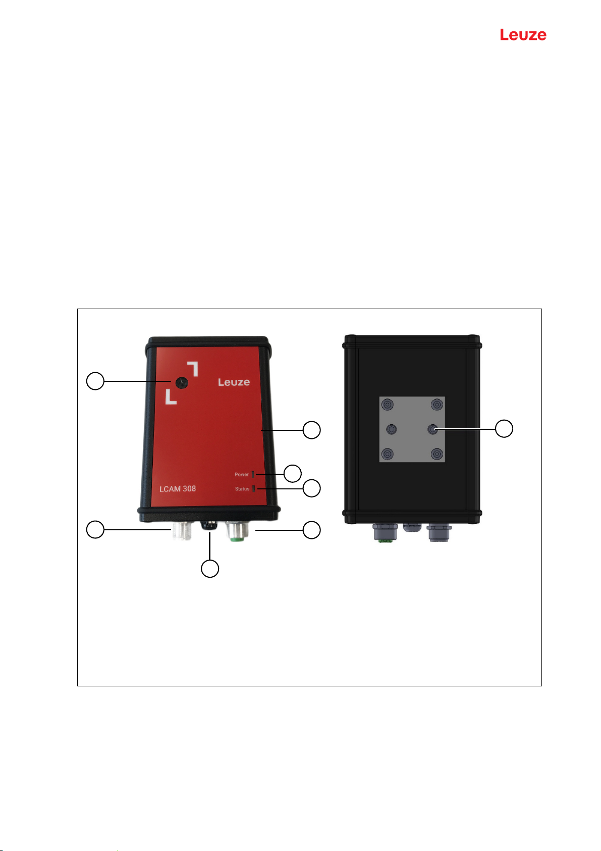
3.1 Device overview. . . . . . . . . . . . . . . . . . . . . . . . . . . . . . . . . . . . . . . . . . . . . . . . . . . . . . . . . . . . . . . . . 6
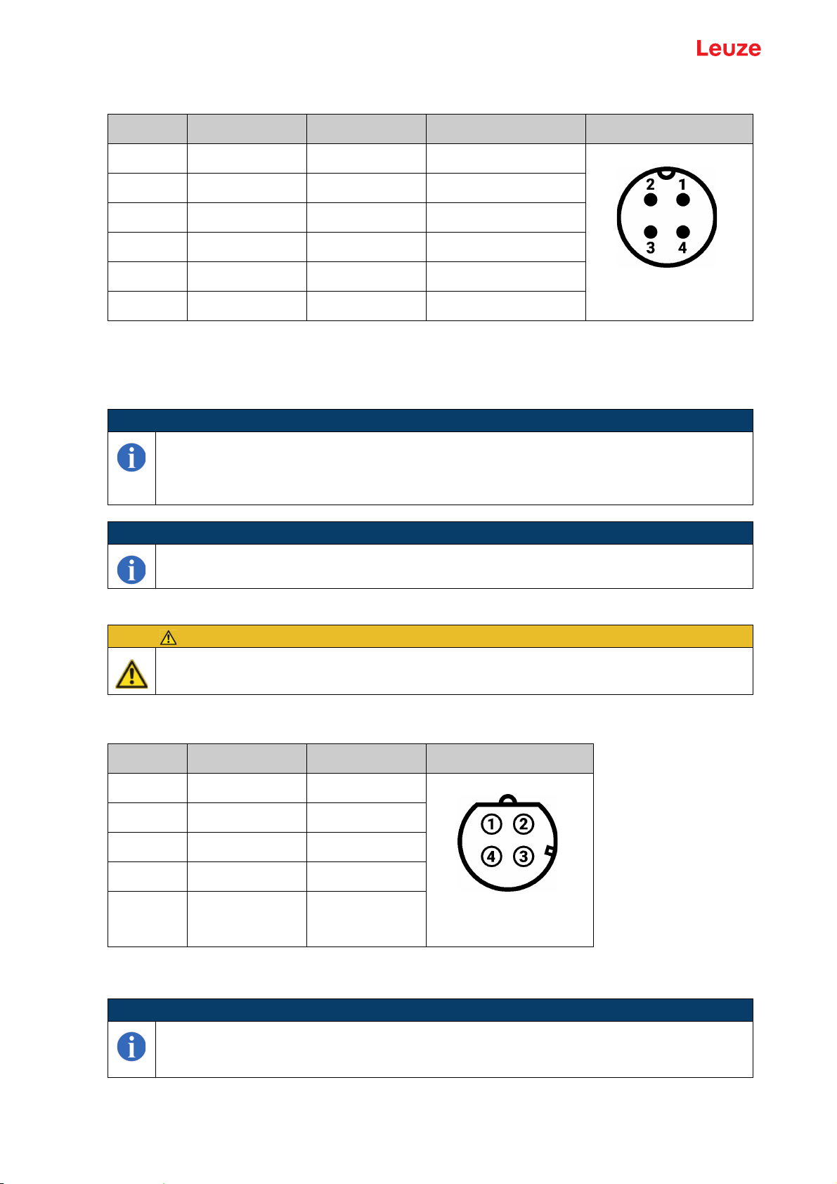
3.2 Power supply and digital input . . . . . . . . . . . . . . . . . . . . . . . . . . . . . . . . . . . . . . . . . . . . . . . . . . . . . . 7
3.3 Ethernet interface . . . . . . . . . . . . . . . . . . . . . . . . . . . . . . . . . . . . . . . . . . . . . . . . . . . . . . . . . . . . . . . 7
3.4 NFC tag . . . . . . . . . . . . . . . . . . . . . . . . . . . . . . . . . . . . . . . . . . . . . . . . . . . . . . . . . . . . . . . . . . . . . . . 8
3.5 Optics. . . . . . . . . . . . . . . . . . . . . . . . . . . . . . . . . . . . . . . . . . . . . . . . . . . . . . . . . . . . . . . . . . . . . . . . . 8
3.6 Heater . . . . . . . . . . . . . . . . . . . . . . . . . . . . . . . . . . . . . . . . . . . . . . . . . . . . . . . . . . . . . . . . . . . . . . . . 8
3.7 Display elements . . . . . . . . . . . . . . . . . . . . . . . . . . . . . . . . . . . . . . . . . . . . . . . . . . . . . . . . . . . . . . . . 8
3.8 microSD card . . . . . . . . . . . . . . . . . . . . . . . . . . . . . . . . . . . . . . . . . . . . . . . . . . . . . . . . . . . . . . . . . . . 9
3.9 Housing . . . . . . . . . . . . . . . . . . . . . . . . . . . . . . . . . . . . . . . . . . . . . . . . . . . . . . . . . . . . . . . . . . . . . . . 9
3.10 Regulations, Directives and standards . . . . . . . . . . . . . . . . . . . . . . . . . . . . . . . . . . . . . . . . . . . . . . . 9
3.11 Technical Data. . . . . . . . . . . . . . . . . . . . . . . . . . . . . . . . . . . . . . . . . . . . . . . . . . . . . . . . . . . . . . . . . . 9
3.12 System requirements. . . . . . . . . . . . . . . . . . . . . . . . . . . . . . . . . . . . . . . . . . . . . . . . . . . . . . . . . . . . 11
3.13 Operation limits and recommendations . . . . . . . . . . . . . . . . . . . . . . . . . . . . . . . . . . . . . . . . . . . . . . 12
4 Mounting and connecting . . . . . . . . . . . . . . . . . . . . . . . . . . . . . . . . . . . . . . . . . . . . . . . 13
5 Features . . . . . . . . . . . . . . . . . . . . . . . . . . . . . . . . . . . . . . . . . . . . . . . . . . . . . . . . . . . . 15
5.1 Streaming . . . . . . . . . . . . . . . . . . . . . . . . . . . . . . . . . . . . . . . . . . . . . . . . . . . . . . . . . . . . . . . . . . . . 15
5.2 Recording . . . . . . . . . . . . . . . . . . . . . . . . . . . . . . . . . . . . . . . . . . . . . . . . . . . . . . . . . . . . . . . . . . . . 15
5.3 Text overlay . . . . . . . . . . . . . . . . . . . . . . . . . . . . . . . . . . . . . . . . . . . . . . . . . . . . . . . . . . . . . . . . . . . 16
5.4 Access protection . . . . . . . . . . . . . . . . . . . . . . . . . . . . . . . . . . . . . . . . . . . . . . . . . . . . . . . . . . . . . . 16
5.5 Network . . . . . . . . . . . . . . . . . . . . . . . . . . . . . . . . . . . . . . . . . . . . . . . . . . . . . . . . . . . . . . . . . . . . . . 16
5.6 Heater . . . . . . . . . . . . . . . . . . . . . . . . . . . . . . . . . . . . . . . . . . . . . . . . . . . . . . . . . . . . . . . . . . . . . . . 16
5.7 NFC Tag . . . . . . . . . . . . . . . . . . . . . . . . . . . . . . . . . . . . . . . . . . . . . . . . . . . . . . . . . . . . . . . . . . . . . 16
6 User Interface. . . . . . . . . . . . . . . . . . . . . . . . . . . . . . . . . . . . . . . . . . . . . . . . . . . . . . . . 17
6.1 Main page / Live . . . . . . . . . . . . . . . . . . . . . . . . . . . . . . . . . . . . . . . . . . . . . . . . . . . . . . . . . . . . . . . 17
6.2 Events . . . . . . . . . . . . . . . . . . . . . . . . . . . . . . . . . . . . . . . . . . . . . . . . . . . . . . . . . . . . . . . . . . . . . . . 17
6.3 Settings . . . . . . . . . . . . . . . . . . . . . . . . . . . . . . . . . . . . . . . . . . . . . . . . . . . . . . . . . . . . . . . . . . . . . . 18
6.4 System. . . . . . . . . . . . . . . . . . . . . . . . . . . . . . . . . . . . . . . . . . . . . . . . . . . . . . . . . . . . . . . . . . . . . . . 21
6.5 Update . . . . . . . . . . . . . . . . . . . . . . . . . . . . . . . . . . . . . . . . . . . . . . . . . . . . . . . . . . . . . . . . . . . . . . . 21
7 Service, maintenance and repair . . . . . . . . . . . . . . . . . . . . . . . . . . . . . . . . . . . . . . . . . 23
7.1 Cleaning. . . . . . . . . . . . . . . . . . . . . . . . . . . . . . . . . . . . . . . . . . . . . . . . . . . . . . . . . . . . . . . . . . . . . . 23
7.2 Service and support. . . . . . . . . . . . . . . . . . . . . . . . . . . . . . . . . . . . . . . . . . . . . . . . . . . . . . . . . . . . . 24
8 Decommissioning and dismantling. . . . . . . . . . . . . . . . . . . . . . . . . . . . . . . . . . . . . . . . 25
9 Disposal . . . . . . . . . . . . . . . . . . . . . . . . . . . . . . . . . . . . . . . . . . . . . . . . . . . . . . . . . . . . 26

General
Leuze electronic GmbH + Co. KG LCAM 308 4
1 General
This manual describes the installation and operation of the device LCAM 308, hereinafter only referred to
as camera, so that its use complies with relevant requirements, particularly regarding safety and electro-
magnetic compatibility when used as intended.
It is therefore essential to read this manual completely and carefully before installing and operating the
camera.
Furthermore, it must be ensured that this manual is available to the end users of the camera for the
complete period of use. This manual may also have to be handed over together with the camera. Any addi-
tions or changes provided by the manufacturer must be incorporated into the operating manual without
delay.
1.1 Manufacturer of the camera
Leuze electronic GmbH+Co. KG
In der Braike 1
73277 Owen
Tel.: +49 7021 – 573 - 0
Fax: +49 7021 – 573 - 199
E-Mail: [email protected]
1.2 Free and Open Source Software (FOSS)
Some parts of the software are licensed under the GNU General Public License or other Open Source and
Free Software licenses. The corresponding list can be found in the download section of this product.
Source code is available on request. Shipping and handling fees may apply.
1.3 Meaning of the symbols
1.4 Intended Use
The camera is intended for use in industrial applications, whereby the camera is supplied with direct
current via a normal direct voltage power supply unit and not via a direct current network.
The camera is used for live streaming and internal recording, in general, for event-based storage of image
and video snapshots. The recording can be triggered by the digital input (hardware) or the network inter-
face (software).
An integrated passive NFC tag is used to read information from the camera, such as serial number or soft-
ware version, wirelessly via the corresponding NFC interface.
To reduce the risk of condensation inside the camera, a heater can be switched on if required. A mounting
socket is used for mounting and fastening for adaptation.
The camera may only be used and operated in accordance with the specifications given under „Technical
Data“. Furthermore, the instructions for „Mounting and connecting“ must be observed.
The camera is only intended for use with the pre-installed software or with updated versions provided by
Leuze.
CAUTION
Instructions and information for reliable use of the camera, especially regarding safety and elec-
tromagnetic compatibility, are marked with this symbol and must be followed to ensure reliable
use.
NOTICE
This symbol indicates information and tips that may be helpful, especially regarding using the
individual camera functions.

Safety instructions
Leuze electronic GmbH + Co. KG LCAM 308 5
2 Safety instructions
The most important safety instructions, some of which appear elsewhere in this document, are summa-
rized here. As mentioned at the beginning of this manual, all instructions and information in this manual
must be followed when using the camera.
CAUTION
All work on the camera, such as installation, connecting, servicing, maintenance, decommis-
sioning, etc., may only be carried out by qualified electrical personnel with the required exper-
tise according to the field of application of the camera.
For all work on and operation of the camera, the applicable accident prevention regulations
for the field of application of the camera must be observed.
Before working on the camera, the connecting cables of the camera must be disconnected.
The camera must be fastened using the mounting socket provided and the M6 female threads
integrated in it.
In case of obvious damage to the camera which affects or may affect the safety and electro-
magnetic compatibility of the camera, and in case of a defect, the camera must be immediate-
ly taken out of operation or not operated at all and secured against inadvertent operation.

Device description
Leuze electronic GmbH + Co. KG LCAM 308 6
3 Device description
The 24V DC powered fixed focus camera with network interface (10BaseT/100Base-TX) and trigger input
is used for live streaming and internal recording of videos in industrial applications.
In addition to post-triggering the recording feature supports pre-triggering to capture actions that occur
before the trigger moment. This might be useful for applications where unexpected events and operations
shall be saved for further examination.
As the camera can be used at ambient temperatures as low as -30 °C, a software-adjustable heater is inte-
grated to minimize the risk of condensation in the lens area of the camera.
Two status LEDs indicate the operating status and may provide support for error analysis.
An NFC tag is integrated in the camera to enable device information to be read independently of the
network interface and even when the power supply is disconnected.
An IP65 housing, a mounting plate attached to the camera with two M6 internal threads and the design of
the two connector plugs (supply/digital input and Ethernet) as M12 variants ensure a robust design of the
complete device.
The camera complies with the applicable requirements of the EU directives, provided that the camera is
operated and installed in accordance with this manual.
3.1 Device overview
Figure 3.1: Camera components
5
1
6
4
2
3
7
8
1Fixed focus camera
2NFC tag antenna
3Power LED
4Status LED
5Power supply and digital input connector
6Ethernet connector
7Pressure compensation element
8Mounting socket

Device description
Leuze electronic GmbH + Co. KG LCAM 308 7
3.2 Power supply and digital input
The maximum input current of the camera is 200 mA over the entire input voltage range with lens heating
deactivated. When lens heating is activated, this maximum input current is 700 mA.
By triggering the digital input DIGIN, recording a video file is initiated.
The maximum digital input current is 7 mA over the complete specified digital input voltage range.
3.3 Ethernet interface
A network interface is used for IPv4 communication with the camera.
Pin Signal Function Specification
1 V+ Power supply + 18..28 V DC
2 DIGIN Digital input Low: 0..5 V DC
High: 16..32 V DC
3 V- Power supply - 0 V
4 NU Not used N/A
Housing NC Not connected N/A
Table 3.1: Pinout power supply and digital input
NOTICE
This requires a rising edge at the DIGIN input into the logical "High" range starting from the
specified logical "Low" range and a corresponding minimum pulse length of 20 ms. A logic
"low" signal must also be present for 20 ms for retriggering. Furthermore, after a trigger is
accepted, renewed acceptance is blocked by software for 2 s.
NOTICE
Trigger signals with a pulse length of < 1.5 ms are not accepted. Pulses with length between
1.5 ms and 20 ms can eventually cause a trigger.
CAUTION
The power supply must be provided by a normal DC power supply unit. Connection to a direct
current supply network is permissible.
M12-A, plug, 4-pole,
not shielded
Pin Signal Function
1 TX+ Transmit data +
2 RX+ Receive data +
3 TX- Transmit data -
4 RX- Receive data -
Housing Shield Shield
Table 3.2: Pinout ethernet
NOTICE
According to the 10BaseT/100Base-TX interface standards, this results in a maximum trans-
fer rate of 10/100 MBit and a maximum cable length of 100 m, whereby at least one Cat. 5e
network cable must be used.
M12-D, jack, 4-pole,
shielded

Device description
Leuze electronic GmbH + Co. KG LCAM 308 8
3.4 NFC tag
A dynamic IEC 15693 type 5 NFC tag is installed on the camera. Information stored on it, e.g. serial
number, software version, etc., can be read out by means of an NFC-capable reader (e.g. smartphone with
corresponding function).
For the position of please refer to Figure 3.1
The NFC interface is based on RFID and operates with a nominal carrier frequency of 13.56 MHz.
3.5 Optics
The camera used to record images and videos has a viewing angle of 62.2 ° horizontally and 48.8 ° verti-
cally.
The focal length of the lens is 3.04 mm and the focal ratio is 2.
The built-in sensor is of the CMOS type, has a resolution of 8 MP and a sensor image area of
3.68 mm x 2.76 mm.
To avoid the image quality being affected by IR radiation, an IR cut filter is installed.
3.6 Heater
To reduce condensation in the camera lens area, especially in cold environments, a heater is integrated
in the camera, which can be activated via software interface if required.
The temperature in the heating area is controlled by a two-point regulator. Depending on the status of the
controller, the heating power has a nominal value of P = 0 W ("off") or, depending on the supply voltage
Vcc, P = Vcc2/50 ("on", 18 V --> 6.5 W, 24 V --> 11.5 W, ...).
3.7 Display elements
Two LEDs on the front of the camera indicate the operating status. The Power LED lights up green, the
Status LED is multicolored.
NOTICE
The ethernet shield is capacitively connected to the supply ground via a 100 nF capacitor, oth-
erwise there is no direct connection to the supply ground (V-).
NOTICE
The NFC tag is powered by the reader and thus readable even if the camera is not powered.
It can be used, for example, to check the IP address of a camera.
NOTICE
The NFC antenna of the reader used must be placed as close, flat and central as possible
above the NFC symbol of the camera (see Figure 3.1).
NOTICE
The focus is a fixed focus (object distance when adjusted for optimum sharpness: 1 m).
NOTICE
In order to avoid intolerably high temperatures in the event of a software-related loss of con-
trol, a software-independent overtemperature shutdown for the heating unit is integrated in the
camera (shutdown value: 103 °C +/- 2.5 °C).
CAUTION
The specified shutdown value refers to the position of the overtemperature sensor in the heat-
ing area, other areas may well be even warmer.

Device description
Leuze electronic GmbH + Co. KG LCAM 308 9
3.8 microSD card
For the storage of video recordings an 8 GB industrial microSD card (class 10 U1) is installed in the
camera.
3.9 Housing
The camera has a powder-coated aluminum housing and a glass front panel. The main dimensions of the
camera body are 114 x 85 x 35 mm (l x w x h). The mounting socket is fixed to the body and not remov-
able.
3.10 Regulations, Directives and standards
The Directives 2014/53/EU (Radio equipment), 2001/95/EC (General product safety), 2011/65/EU
(RoHS), 2012/19/EU (WEEE) and the Regulation (EC) No 1907/2006 (REACH) apply to the camera.
Among others, the harmonized standards EN 61326-1:2013 (Electrical equipment for measurement,
control and laboratory use - EMC requirements - Part 1: General requirements) and ETSI EN 300 330
V2.1.1 (Short range devices) were used to assess compliance with applicable requirements of the EU
Directives.
3.11 Technical Data
LED Color Function
Power Green Lights up while camera is powered
Status Blue Lights up blue from trigger to end of recording
Status Yellow Lights up yellow while initializing the system
Table 3.3: Function assignment of the LEDs
CAUTION
Removing or replacing the microSD card is only intended for service purposes. In case of ser-
vice, the two housing cover screws on the side with the microSD card symbol must be
removed. The corresponding screw covers must be opened first.
NOTICE
The integrated pressure compensation element reduces the risk of condensation inside the
camera.
NOTICE
The camera housing is capacitively connected to the supply ground by contact to the housing
of the ethernet connector via a 100 nF capacitor, otherwise there is no direct connection to the
supply ground (V-).
NOTICE
A mounting socket with two M6 internal threads for adaptation is provided for fastening the
camera (see drawing below).
Power supply
Supply voltage 18..28 V DC
Input current (heater not activated) < 200 mA
Input current (heater activated) < 700 mA
Digital input
Table 3.4: Technical Data

Device description
Leuze electronic GmbH + Co. KG LCAM 308 10
Signal voltage high 16..32 V DC
Signal voltage low 0..5 V DC
Input current < 7 mA
Trigger type Positive edge
Length of trigger pulse Min. 20 ms
Input filter > 1.5 ms
Ethernet interface
Transmission rates 10/100 MBit/s (10BaseT/100Base-TX)
Transmission medium At least ethernet Cat. 5e cable, max. 100 m
NFC tag
Nominal carrier frequency Typ. 13.56 MHz
Camera
Focus type Fixed focus (Adjusted for 0.5 m to 8, optimum sharpness
distance: 1 m)
Horizontal field of view max.a) 62.2 °
Vertical field of view max.a) 48.8 °
Focal length 3.04 mm
Focal ratio 2
IR cut filter Yes
Sensor type CMOS
Sensor image area 3.68 mm x 2.76 mm
Heater
Controller type Two-point controller
Max. heating power depending on
supply voltage
18 V DC: typ. 6.5 W
24 V DC: typ. 11.5 W
28 V DC: typ. 15.5 W
Max. current consumption depending
on supply voltage
18 V DC: max. 400 mA
24 V DC: max. 500 mA
28 V DC: max. 600 mA
Overtemperature shutdown
threshold
103 °C +/- 2.5 °C
At position of overtemperature sensor, other positions can
reach higher temperatures
SD card
Type microSD, industrial, class 10 U1
Memory size 8 GB
Connection data
Power supply including digital input M12-A, plug, 4-pole, not shielded
Table 3.4: Technical Data

Device description
Leuze electronic GmbH + Co. KG LCAM 308 11
3.12 System requirements
Ports
To ensure proper functionality of the system the following ports shall not be blocked by a firewall in the
cameras network.
Ethernet M12-D, jack, 4-pole, shielded
Mechanical data
Dimensions basic housing (l x w x h) 114 x 85 x 35 mm
Base material housing Al Mg Si 0.5
Coating of housing Powder-coated, black
Front panel Fully bonded glass
Fastening the camera Via mounting socket
Maximum torque for camera
fastening
Up to manufacturing date 09/2020: 15 Ncm
From manufacturing date 10/2020: 1 Nm
Weight 0.3 kg
Ambient conditions
Ambient temperature during
operation and storage
-30..+50 °C
Relative humidity during storage and
transport
No condensation
Protection class IP65
Regulations, Directives and standards
2014/53/EU Radio equipment Directive
2001/95/EC General product safety Directive
EN 61326-1:2013 Electrical equipment for measurement, control and laboratory
use - EMC requirements - Part 1: General requirements
ETSI EN 300 330 V2.1.1 Short range devices
(EC) No 1907/2006 REACH Regulation
2011/65/EU RoHS Directive
2012/19/EU WEEE Directive
a) Field of view depends on selected resolution and rotation
Table 3.4: Technical Data
Port Protocol Feature
80 TCP Web Application
5001 UDP Text overlay
5002 UDP Event trigger
Table 3.5: Ports

Device description
Leuze electronic GmbH + Co. KG LCAM 308 12
Browser Support
3.13 Operation limits and recommendations
Operation limits are enforced automatically by the system. Operation recommendations indicate the tested
boundaries of the system by the manufacturer. If use takes place beyond these limits, performance may
decrease and support from the manufacturer may not always be guaranteed.
8080 TCP Web Application
8554 or 554 TCP and UDP RTSP stream
53100 UDP Management tool
Google Chrome > 84 (stable channel)
Table 3.6: Browser Support
Port Protocol Feature
Table 3.5: Ports
Characteristic Type Value
microSD memory capacity [GB] Recommendation 8
Recording count Recommendation 10.000
Min. time interval between recordings [s] Limit 2
Concurrent recordings Limit 3a)
a) Only 1 recording if resolution is set to 1920x1080
Concurrent HTTP connections Limit 8
Concurrent MJPEG streams Recommendation 2
Concurrent RTSP streams Recommendation 1
Table 3.7: Operation limits and recommendations

Mounting and connecting
Leuze electronic GmbH + Co. KG LCAM 308 13
4 Mounting and connecting
CAUTION
The camera must be installed using the M6 female threads in the mounting socket (see draw-
ing). No other type of mounting is permitted.
CAUTION
Fasteners that are screwed into the M6 female threads may be tightened depending on the
manufacturing date to a maximum torque of 1 Nm (from manufacturing date 10/2020).
CAUTION
The camera must be fastened regarding the operating conditions. The mounting must be
checked and maintained at regular intervals.
NOTICE
For a vibration-resistant screw connection, we recommend screw locking lacquer, e.g. Loctite
243 from Henkel.
CAUTION
The two electrical connections of the camera must also be made with M12 connectors, includ-
ing mechanical locking via the M12 threads, according to the connectors of the camera. These
mechanical interlocks must be hand-tightened after plugging in the connection cables. The
fastening of the connections must be carried out in accordance with the operating conditions
and conditions of use and, if necessary, checked and repaired regularly so that they do not
become loose over time.
CAUTION
When selecting the connecting cables, the information in this manual and the data sheet for
the camera, especially with regard to the electrical specifications, have to be taken into
account.
CAUTION
The electrical connection of the camera must not be established until the mounting according
to the specifications has been carried out.

Mounting and connecting
Leuze electronic GmbH + Co. KG LCAM 308 14
Figure 4.1: Mechanical drawing of housing, position of mounting socket
0WLHIGHHS[
0[
0[
1Mounting socket
1

Features
Leuze electronic GmbH + Co. KG LCAM 308 15
5 Features
5.1 Streaming
5.2 Recording
The camera can record the video image on a trigger signal. Recording starts the set pre-trigger time before
the trigger point and ends the set post-trigger time after the trigger point.
Recording video specifications:
Recording with 1920x1080
Live Stream, Recording and RTSP share the processing power of the camera, which is limited. Recording
with a resolution of 1920x1080 is most computation-intensive and can cause the live stream to have a very
low framerate. To reduce impact on the live stream or when noticing any other performance problems, it
is recommended to disable the RTSP stream when recoding with 1920x1080.
Only one recording can run at a time when using 1920x1080.
When using a recording resolution of 1920x1080, the field of view is reduced due to sensor limitations.
This applies for all streams, although only the recording supports 1920x1080.
Trigger options
• Digital input
A rising edge on the digital input will trigger a recording
•UDP
Send the string TRIG to UDP port 5002 on the camera
• Web frontend
The trigger button on the top right in the frontend can be used as manual trigger
If a trigger signal is detected, the blue LED Status on the camera will light up until the end of all running
recordings. If the recording cannot be saved, the blue LED will flash several times. Multiple recordings can
overlap, but at least 2s must elapse between each trigger. No more than three recordings can run at the
same time.
To ensure that there is always enough free memory, there is a deactivatable function that deletes the
oldest videos if necessary, to ensure enough free storage.
Stream Resolution FPS Codec / Contai-
ner
URL
HD 1280 x 720,
1024 x 576,
960 x 540,
800 x 450,
640 x 360
24 MJPEG http://<camera-ip>/stream-hd
RTSP 640 x 360 3 H264 RTSP rtsp://<camera-ip>:<rtsp-port>/<rtsp-
path>
Table 5.1: Streaming
Resolution FPS Codec / Container
1920x1080, 1280 x 720, 1024 x 576, 960 x 540, 800 x 450, 640
x 360
24 H264 MP4,
adjustable quality
Table 5.2: Recording
NOTICE
Recording failure
A recording failure is indicated by the blue led flashing several times after a trigger occurred.
Possible causes include
• Memory card full
• Memory card missing
• Memory card faulty

Features
Leuze electronic GmbH + Co. KG LCAM 308 16
5.3 Text overlay
Three fields of information can be overlayed at the top edge of the screen:
• Camera Name
The name of the camera set in the settings, maximum 255 characters long
• Date and Time
Date and time are obtained from the NTP server
• User Defined Text
The custom text is set by sending it to UDP port 5001 of the camera, it will be truncated after
255 characters if necessary. Only Ascii characters up to 127 are supported, no umlauts. The user-
defined text is not stored persistently and will be reset each time the camera is started.
For the overlay, the fields are combined, truncated to 255 characters and overlayed at the top of the
screen. An automatic line break is performed if necessary. If required, a black background for the white
overlay text can be configured in the settings.
5.4 Access protection
Two users are available:
• viewer
•admin
No password is set for either user at delivery. If a password is set, a prompt to log in appears when a page
is called.
The user admin has no restrictions.
The user viewer may view streams and recordings but may not make any changes. He is not allowed to
change any settings, delete videos or perform updates.
The names of both users can be changed.
5.5 Network
The camera has a 100MBit Ethernet interface. It can have a static IP or obtain one using DHCP. If DHCP
is activated but not available, the static IP will always be used as fallback.
5.6 Heater
The camera has an integrated heater to reduce condensation on the lens cover especially in cold environ-
ments. The heater features the three levels Low, Med, High and is disabled by default.
If condensation occurs, the heater level should be increased until the lens cover stays clear. It will take a
few minutes until a higher heater level has an effect on the condensation as the case has to be warmed up.
The heater can safely stay enabled on every level over the full operating temperature range. Internal
temperature control prevents overheating in warm environments.
5.7 NFC Tag
A dynamic IEC 15693 Type 5 NFC tag is installed on the camera, in which some information about the
camera is stored:
• Current IP address
• Static/fallback IP address
• Software version
• Hardware version
• MAC address of ethernet interface
• Serial number
• Timestamp of last update and NTP sync status
The NFC tag can be read with compatible reader or a NFC-enabled smartphone. Current android smart-
phones will show the information without any additional app while iPhones need a NFC reader app.
The information in the NFC tag is updated once on every boot. The IP address is updated a second time
one minute after each boot to have some delay for the DHCP request.
The NFC tag is powered by the reader (e.g. smartphone) and thus readable even if the camera is not
powered. It can be used, for example, to check the unknown static IP address of a camera.

User Interface
Leuze electronic GmbH + Co. KG LCAM 308 17
6 User Interface
The user interface can be reached via the URL http://<camera-ip>
6.1 Main page / Live
The start page (Live) of the web interface consists of four areas.
Figure 6.1: Start page (Live)
•Livestream
• Manual trigger button
• Snapshot1 download button
• Active events count indicator
• Last Events
• Camera information
• Camera name
• IP address
• MAC address of ethernet interface
6.2 Events
The events view allows access to the recordings. They are represented by thumbnails of a still image taken
at the trigger time. The recordings are spread over several pages, which can be selected using the
navigation above the thumbnails. The storage usage is displayed next to the navigation.
The displayed events can be filtered by selecting a date range from the drop-down on the top left.
1. Snapshots are taken with Live stream resolution

User Interface
Leuze electronic GmbH + Co. KG LCAM 308 18
Figure 6.2: Events
A click on the thumbnail plays the recording. Below are three buttons:
• Download Video
Starts the download of the video
• Download Snapshot1
Download still image taken at the trigger time
• Delete
Deletes the video after a confirmation
6.3 Settings
All camera settings are stored on the SD card in the file ipcam_settings.json. If this file does not exist or is
invalid due to incorrect manual editing, the default settings are loaded and a message is displayed at the
top of the settings page.
By saving the settings on the settings page, the file ipcam_settings.json is created or overwritten.
To reset the camera to factory defaults, this file can be deleted from the SD card. This is only necessary
if the password of the admin user has been forgotten. Otherwise all settings can be edited through the user
interface.
By clicking the Backup/Restore button, you can either download the settings file or restore the settings
from a previously backed up file. The backup file should not be edited manually.
1. Snapshots are taken with Live stream resolution

User Interface
Leuze electronic GmbH + Co. KG LCAM 308 19
Figure 6.3: Settings
Camera
Setting Default Input restriction Description
Camera
Camera name <empty> 0-255 characters, a-z,
A-Z, 0-9, '-'; no '-' as first
or last character
Freely selectable name of the camera,
is displayed on the start page and can
be overlayed on the camera stream.
Rotation 0° 0°, 90°, 180°, 270° Image rotation. The aspect ratio
remains the same, causing the image
to be enlarged at 90 ° and 270 °.
Overlays Camera Name,
Date and Time,
Custom overlay,
Text background
The activated elements are displayed
at the top of the camera image. The
overlay is limited to 255 characters
and will be shortened if necessary.
Heater off Off, Low, Med, High Activation and setting of the heating
level
Live Stream
Live stream
resolution
1280 x 720 1280 x 720, 1024 x 576,
960 x 540, 800 x 450,
640 x 360
Live stream resolution
Live stream
quality
100 0-100% Live stream quality
RTSP Stream
Enable RTSP active Enable RTSP stream, not
recommended when using 1920x1080
recording resolution to avoid live
stream frame dropping
Table 6.1: Camera

User Interface
Leuze electronic GmbH + Co. KG LCAM 308 20
RTSP path <empty> 0-30 characters, a-z,
A-Z, 0-9
Path segment of RTSP URI
RTSP port 8554 554, 8554 RTSP port
Recording
Pre-event
recording time [s]
10 1-60 Recording time before the trigger point
Post-event
recording time [s]
10 1-60 Recording time after the trigger point
Recording stream
resolution
640x360 1920 x 1080,
1280 x 720, 1024 x 576,
960 x 540, 800 x 450,
640 x 360
Recording stream resolution
Recording stream
quality
50 0-100% Recording stream quality
Delete oldest
when memory is
full
active Deletes the oldest videos if necessary.
Access
admin user name admin 1-255 characters User name for admin user
admin password <empty> 1-50 characters The password for the user admin.
Password protection can be disabled
viewer user name viewer 1-255 characters User name for viewer user
viewer password <empty> 1-50 characters The password for the user viewer.
Password protection can be disabled
Network
IP address 192.168.60.101 IPv4 address The IPv4 address of the camera. If
DHCP is enabled, this is used as
fallback.
Netmask (CIDR) 24 0-30 Net mask in CIDR notation
Gateway IP
address
<empty> IPv4 address, optional The gateway is required if the NTP
server is in another subnet.
DNS server IP
address
<empty> IPv4 address, optional DNS server, currently not required
DHCP active Enables DHCP. If no DHCP server is
available, the camera uses the set IP
address as static address.
NTP server
address
<empty> IPv4 address, optional NTP server. Is required to set the
camera time.
Timezone Europe/Berlin Camera timezone for local time in
overlay and recordings
Setting Default Input restriction Description
Table 6.1: Camera
This manual suits for next models
2
Table of contents
Popular Security Camera manuals by other brands

Samsung
Samsung SID-560 user manual

Atlantis Land
Atlantis Land A02-WIPCAM-11B Specifications

Bunker Hill Security
Bunker Hill Security 95914 Set up and operating instructions

Lorex
Lorex LNC254 series user guide

TELEDYNE FLIR
TELEDYNE FLIR QuasarGen III Quick install guide

Samsung
Samsung SCV-3080 Series user manual