lev-co SQBI User manual

1
OWNER’S MANUAL
SQBI Direct Drive and Belt Driven Fans
***IMPORTANT***
THIS MANUAL CONTAINS PRECAUTIONARY STATEMENTS RELATING TO WORKER SAFETY. READ AND
SAVE THIS MANUAL COMPLETELY AND COMPLY AS DIRECTED. ALL THE POTENTIAL HAZARDS OF DUST
AND MIST CONTROL SYSTEMS AND EQUIPMENT ARE IMPOSSIBLE TO LIST; THEREFORE, OBTAIN THE
SERVICES OF A PROFESSIONAL INSTALLER. A FIRE PROTECTION EXPERT SHOULD BE OBTAINED IN
THE EVENT THE PRODUCT IS INTENDED FOR USES WHICH PRESENT A POTENTIAL RISK OF FIRE OR FIRE
PROPAGATION. REFER TO APPROPRIATE AUTHORITIES, AND DISCUSS YOUR INTENDED USE WITH A LEV-
CO REPRESENTANT. WORKERS HANDLING EQUIPMENT OR SYSTEMS SHOULD BE INSTRUCTED TO
CONDUCT THEMSELVES IN A SAFE MANNER.
The Local Exhaust & Ventilation Company
www.LEV-CO.com
Phone: 888.862.5356; Fax: 866.840.9923
•INTRODUCTION
•PRODUCT PRESENTATION
•UNPACKING
•INSTALLATION
•OPERATION
•MAINTENANCE
•REPLACEMENT PARTS

2
ALWAYS USE LEV-CO REPLACEMENT PARTS TO MAINTAIN WARRANTY.
TO ORDER SPARE PARTS CONTACT US:
1050 BROCK ROAD, Unit 22-24
Pickering, ON, CANADA L1W 3X4
Phone 905.831.7001 or 888.862.5356
Fax: 905.831.7443 or 866.840.9923
E-mail: [email protected]
Website: http://www.lev-co.com

3
TABLE OF CONTENTS
1. General Safety Notes............................................................................................................. 4
2. Receiving................................................................................................................................. 4
3. Handling ................................................................................................................................. 4
4. General Installation Instructions ...................................................................................... 5
5. Operation................................................................................................................................ 5
6. General Maintenance ............................................................................................................ 6
7. V-belt Drives .......................................................................................................................... 6
8. Bearing Maintenance .......................................................................................................... 7
9. Warranty................................................................................................................................. 8
11. Troubleshooting.................................................................................................................... 9
12. Assembly Drawing................................................................................................................ 11

4
ALL FANS AND BLOWERS SHOWN HAVE ROTATING PARTS AND PINCH POINTS. SEVERE
PERSONAL INJURY CAN RESULT IF OPERATED WITHOUT GUARDS. STAY AWAY FROM
ROTATING EQUIPMENT UNLESS IT IS DISCONNECTED FROM ITS POWER SOURCE AND
ALL ROTATING PARTS HAVE STOPPED MOVING. READ ALL OPERATING INSTRUCTIONS
CONTAINED HEREIN BEFORE INSTALLING EQUIPMENT.
NO GUARANTEE OF ANY LEVEL OF SPARK RESISTANCE IS IMPLIED BY SPARK
RESISTANT CONSTRUCTION. IT HAS BEEN DEMONSTRATED THAT ALUMINUM
IMPELLERS RUBBING ON RUSTY STEEL MAY CAUSE HIGH INTENSITY SPARKS. AIR
STREAM MATERIAL AND DEBRIS OR OTHER SYSTEM FACTORS MAY ALSO CAUSE
SPARKS.
GENERAL SAFETY NOTES
1. Rotating parts including shaft and V-belt drives must be properly guarded to prevent personal injury.
2. Electrical wiring must be accomplished by a qualified electrician in accordance with all applicable codes.
3. Care should be taken:
• Not to run fan above its safe speed
• Not to operate in excessive temperatures
• Not to operate in dangerous environments.
• Read all instructions carefully.
RECEIVING
Receiving Inspection
When unit is received, inspect immediately for damaged or missing parts. Even though all units are
carefully inspected and prepared for shipment at the factory, rough handling en route may cause concealed
damage or cause nuts, set screws, bolts or locking collars to work loose. Be certain all fasteners are tightened
securely. Rotate wheel by hand to verify that it rotates freely and that there are no obstructions.
Inspect all shipments carefully for damage. THE RECEIVER MUST NOTE ANY DAMAGE ON
THE CARRIER’S BILL OF LADING AND FILE A CLAIM IMMEDIATELY WITH THE FREIGHT
COMPANY IN THE CASE OF ANY DAMAGE. Keep a record of all equipment received, including
inspection details and date of receipt because of the possibility of partial shipments.
HANDLING
Handle your equipment with care. Some fans are provided with lifting lugs or holes for easy
handling. Others must be handled using nylon straps or well-padded chains and cables which protect the
fan’s coating and housing. Spreader bars should be used when lifting large parts.
Centrifugal fans are best lifted using one strap under the fan’s scroll and another strap around the
bearing base. DO NOT LIFT CENTRIFUGAL FANS BY THE FAN SHAFT, WHEEL, FLANGES, INLET
SUPPORT OR MOTOR EYE BOLT.

5
GENERAL INSTALLATION INSTRUCTIONS
Foundations
Fan foundation must be flat, level and rigid. Where foundation is not completely flat, shims must be
placed under fan support at each anchor bolt as required. Bolting fan to an uneven foundation distorts
alignment and causes vibration.
Structural steel foundations should be heavily cross-braced for load support.
Table #1
TORQUE VALUES FOR SPLIT TAPER BUSHINGS
Bushing Size MINIMUM RECOMMENDED TORQUE
(INCH-LBS)
H 95
B & P 192
Q & R 350
Table #2
SET SCREW TORQUE VALUES
SET SCREW SIZE MINIMUM REQUIRED
TORQUE (INCH-LBS)
Diameter & No.
of Threads/Inch Hex Size Across Flats
(Allen Wrench)
1/4-20
5/16-18 1/8"
5/32" 65
165
3/8-16
7/16-14 3/16"
7/32" 228
348
1/2-13
5/8-11 1/4"
5/16" 504
1104
NOTE: If wheel set screws are loosened and/or wheel is removed from shaft, set screws must be replaced.
Set screws cannot be used more than once. Use knurled, cup point set screws with a locking patch.
OPERATION
Before Connecting Power
1. Inspect all fasteners and retighten if necessary:
a. Foundation bolts.
b. Set screws in fan and wheel and V-belt drive (See Table #1 on preceding page).
c. Housing, bearing and motor mounting.
2. Inspection doors should be tight and sealed.
3. Bearings should be checked for alignment and lubrication (See Bearing Maintenance, pages 4 and 5).
4. Turn rotating assembly by hand to insure that it does not strike housing. If the wheel strikes the housing,
the wheel may have moved on the shaft or the bearings may have shifted in transit. Correction must be
made prior to start up.
5. Check motor to insure proper speed and electrical characteristics.
6. Check V-belt drive for alignment and correct belt tension.
7. After wiring, energize motor for one second to check for proper rotation.

6
GENERAL MAINTENANCE
The key to good fan maintenance is a regular and systematic inspection of all fan parts. Severity of
the application should determine frequency of inspection. The components requiring service are generally
the moving parts which include bearings, fan wheel, belts, sheaves and motor.
Cast Aluminum & Metal Parts
Cast aluminum and steel parts usually do not require maintenance during the life of the unit except painted
metal surfaces that may require periodic repainting. In a severe, dirty operation, the wheel should be cleaned
with a wire brush to prevent an accumulation of foreign matter that could result in fan unbalance. After
cleaning wheel, inspect for possible cracks or excessive wear, which can cause unbalance. DO NOT operate
a wheel that is cracked, chipped, has broken blades or excessive wear. NOTE: If wheel set screws are
loosened and/or wheel is removed from shaft, set screws must be replaced. Set screws cannot be used more
than once. Belts on V-belt drive units require periodic inspection and replacement when worn. For multiple
belt drives, belts should be replaced with matched sets.
Motor Maintenance
1. Disconnect or lock out power to motor.
2. Removing dust and dirt: Blow out open type motor windings with low pressure air to remove dust or dirt.
Air pressure above 50 P.S.I. should not be used as high pressure may damage insulation and blow dirt
under loosened tape. Dust accumulation can cause excessive insulation temperatures.
3. Lubrication: The motor bearings and the fan bearings on the belt drive fans should be greased at regular
intervals. Motor manufacturers’ greasing instructions and recommendations should be followed closely.
Avoid the use of a pressure greasing system which tends to fill the bearing chamber completely. Do not
over grease. Use only 1 or 2 shots with a hand gun in most cases. Maximum hand gun rating 40 P.S.I.
Rotate bearings during lubrication where good safety practice permits. NOTE: On motors with non-
regreasable sealed bearings, no lubrication is required for the life of the bearings.
To prevent rusting of bearing parts, the rotor must be rotated at regular intervals (30 days) to assure these
parts are well covered with oil or grease.
V-BELT DRIVES
Care should be taken not to over tighten V-belt drive. Excessive belt tension overloads fan and
motor bearings. It is much less expensive to replace belts worn from slippage than to replace bearings
damaged from excessive loading.
Fans shipped completely assembled have had V-belt drive aligned at the factory. Alignment should be
rechecked before operation as a precaution due to handling during shipment.
A WORD OF CAUTION ABOUT MOTORS
Using your hand to test the running temperature of a motor can be a very painful experience:
Normal body temperature ..................................................................................98.6° F
Threshold of pain caused by heat.....................................................................120.0° F

7
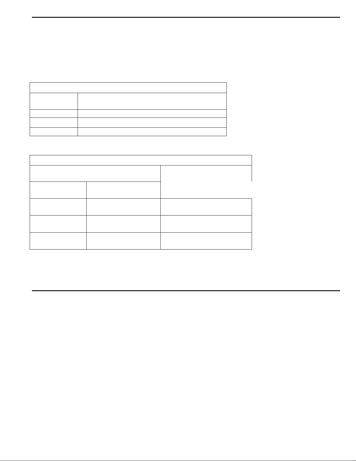
Average temperature of hot tap water..............................................................140.0° F
Average temperature of hot coffee....................................................................180.0° F
Normal operating temperature of a fully loaded electric
motor open type, 70° F ambient temperature ...................................................174.0° F
1. Be sure sheaves are locked in position.
2. Key should be seated firmly in keyway.
3. Place straight edge or taut cord across faces of. driving and driven sheaves to check alignment. The V-belt
drive assembly can be mounted as follows: motor and fan shafts must be parallel with V-belts and at right
angles to the shafts.
4. Start the fan. Check for proper rotation. Run fan at full coat with heavy oil for ease of shaft entry.
Remove oil, speed. A slight bow should appear on slack side of grease, rust or burrs from sheave grooves.
belt. Disconnect power and adjust belt tension by sheave on adjusting motor on its sliding base. All belts
must have some slack on one side.
5. If belts squeal at start up, they may be too loose.
6. When belts have had time to seat in the sheave grooves, then readjust belt tension.
V-belt drive assembly can be mounted as follows:
1. Clean motor and fan shafts. Be sure they are free from corrosive material. Clean bore of sheaves and
coat with heavy oil for ease of shaft entry. Remove oil, grease, rust or burrs from sheave grooves.
2. Place fan sheave on fan shaft and motor sheave on its shaft. Do not pound sheaves on as this may
damage bearings. Tighten sheaves per Table #1 or #2.
3. Move motor on slide base so belts can be placed in grooves of both sheaves without forcing. Do not roll
belts or use a tool to force belts over the grooves.
4. Align fan and motor shafts so they are parallel. The belts should be at right angles to the shafts. A straight
edge or taut cord placed across the face of the sheaves will aid in alignment.
5. Tighten belts by adjusting motor base. Correct tension gives the best drive efficiency. Excessive tension
causes undue bearing pressure.
6. Start the fan and run it at full speed. Adjust belt tension until only a slight bow appears on the slack side of
the belts. If slippage occurs, a squeal will be heard at start-up. Eliminate this squeal by disconnecting or
locking out motor from power source and then tightening up the belts.
7. Give belts a few days running time to become seated in sheave grooves, then readjust belt tension. If the
shafts become scratched or marked, carefully remove sharp edges and high spots such as burrs with
fine emery cloth or honing stone. Avoid getting emery dust in the bearings. Do not apply any belt dressing
unless it is recommended by the drive manufacturer. V-belts are designed for frictional contact between the
grooves and sides of the belts. Dressing will reduce this friction. Belt tension on an adjustable pitch drive is
obtained by moving the motor, not by changing the pitch diameter of the adjustable sheave.
BEARING MAINTENANCE
Sealed Bearings
Sealed for life bearings are pre-lubricated with the correct amount of manufacturer approved ball
bearing grease, and are designed for application where relubrication is not required.
Relubricatable Bearings
The motor bearings and fan bearings on belt drive fans should be greased at regular intervals. Motor
manufacturers greasing instructions and recommendations should be followed closely. Avoid the use of a
pressure greasing system which tends to fill the bearing chamber completely. Do not over grease.
NOTE: On motors with non-regreasable, sealed bearings, no lubrication is required for the life of the
bearing.
Table #3 lists the time intervals between fan greasing to insure proper lubrication in adverse conditions of

8
heat and dust. Use only 1 or 2 shots with a hand gun in most cases. Maximum handgun rating 40 P.S.I.
Table #3
Conditions Around Bearing Operating Temperature of Fan **Greasing Intervals
Fairly Clean up to 120 °F 6-12 months
120°-160°F 2-3 months
160°-200°F plus* 1-2 months
Moderate to up to 160°F 1-2 months
Extremely Dirty 160°-200°F plus* 2-4 weeks
Cold Storage Room every defrosting period or
no more than 4 months
* For fan applications over 200°F: greasing intervals should be from several days to 2 weeks, depending on
the temperature.
** For vertical installations, greasing intervals should be twice as frequent as table values.
The following greases, or one that is equivalent to the general description, are recommended for the
following temperatures or excessive moisture applications.
Operating Conditions Use Grease Equivalent to these Grades
Esso-Beacon #325 (-65°F)
Temperatures -65°F to 0°F Mobil Grease #28 (-65°F)
Shell Oil Aeroshell No. 7 (-100°F)
General Description: Versatile multipurpose microgel thickened synthetic hydrocarbon grease with
corrosion inhibitors, anti-oxidant additives, water resistance tendencies and EP characteristics.
Temperature 0°F to 200°F inclusive Mobil Oil - Mobilux EP #2
(Also use for heavy condensation Shell Oil - Shell Alvania EP #2
or direct splash of water) Chevron - Chevron SRI #2
General Description: Multipurpose NLGI#2 grease from lithium soap with EP characteristics, rust inhibitors,
anti-oxidant additives and good water resistance tendencies.
Temperatures over 200°F Dow Corning-DC44 (400°F) (Not compatible with non-silicon
based greases)
General Description: Versatile multipurpose microgel thickened synthetic hydrocarbon grease with
corrosion inhibitors, anti-oxidant additives, water resistance tendencies and EP
characteristics.
WARRANTY
Lev-co warrants products of its own manufacture against defects of material and workmanship under
normal use and service for a period of (12) months. This warranty does not cover ordinary wear and tear,
abuse, misuse, overloading, negligence, alteration or systems and/or materials not of Seller’s manufacture.
Expenses incurred by Buyer(s) in repairing or replacing any defective product will not be allowed except
where authorized in writing and signed by an officer of the Seller.

9
The obligation of Seller under this warranty shall be limited to repairing or replacing F.O.B. Seller’s
plant, or allowing credit at Seller’s option. This warranty is expressly in lieu of all other warranties
expressed or implied including the warranties of merchantability and fitness for use and of all other
obligations and liabilities of the Seller. The Buyer acknowledges that no other representations were made to
him or relied upon him with respect to the quality or function of the products herein sold.
On equipment furnished by the Seller, but manufactured by others, such as motors, Seller extends the same
warranty as Seller receives from the manufacturer thereof. Repairs for motors should be obtained from
nearest authorized motor service station for the make of motor furnished. All motors used are products of
well-known manufacturers with nationwide service facilities. Check the yellow pages of your telephone
directory for the location of the nearest service shop.
TROUBLESHOOTING
In the event that trouble is experienced in the field, the following are the most common fan difficulties.
These points should be checked in order to prevent needless delay and expense.
1. CAPACITY OR PRESSURE BELOW RATING
a. Incorrect direction of wheel rotation.
b. Speed too slow.
c. Dampers not properly adjusted.
d. Poor fan inlet or outlet conditions (elbows, restrictions).
e. Air leaks in system.
f. Damaged wheel.
g. Total resistance of system higher than anticipated.
h. Wheel mounted backwards on shaft.
i. Fan not properly selected for a high temperature and/or high altitude application.
2. VIBRATION AND NOISE
a. Misalignment of bearings, coupling, wheel or V-belt drive.
b. Unstable foundation or supports.
c. Foreign material in fan causing unbalance.
d. Worn bearings.
e. Damaged wheel or motor.
f. Broken or loose bolts and set screws.
g. Bent shaft.
h. Worn coupling.
i. Fan wheel or drive unbalanced.
j. 120 cycle magnetic hum due to electrical input. Check for high or unbalanced voltage.
k. Fan delivering more than rated capacity.
l. Loose dampers.
m. Speed too high or fan rotating in wrong direction.
n. Vibration transmitted to fan from some other source.
3. OVERHEATED BEARINGS
a. Check bearing lubrication.
b. Poor alignment.
c. Damaged wheel or drive.
d. Bent shaft.

10
e. Abnormal end thrust.
f. Dirt in bearings.
g. Excessive belt tension.
4. OVERLOAD ON MOTOR
a. Speed too high.
b. Fan over capacity due to existing system resistance being lower than original rating.
c. Specific gravity or density of gas above design value.
d. Wrong direction of wheel rotation.
e. Shaft bent.
f. Poor belt alignment.
g. Wheel wedging or binding on fan housing.
h. Bearings improperly lubricated.
i. Motor improperly wired.
j. Defective motor. Motor must be tested by motor manufacturer’s authorized repair shop.

11
MODEL SQBI - Arrangement 4
1. Inlet bell
2. Wheel (SQBI Wheel shown)
3. Housing/base assembly
4. Motor

12
MODEL SQBI - Arrangement 9
1. Housing
2. Wheel (SQBI shown)
3. Motor
4. Inlet Bell
5. Bearing Base
6. Motor Base
7. Shaft and Bearing Assembly
8. Motor Sheave
9. Fan Sheave
10. Belts
11. Belt Guard

13
ALWAYS USE LEV-CO REPLACEMENT PARTS TO MAINTAIN WARRANTY
TO ORDER SPARE PARTS CONTACT LEV-CO
1050 BROCK ROAD, Unit 22-24
Pickering, ON, CANADA L1W 3X4
Phone 905.831.7001 or 888.862.5356
FAX: 905.831.7443 or 866.840.9923
E-MAIL: [email protected]
INTERNET: http://www.lev-co.com
Table of contents
Popular Fan manuals by other brands

NOMA
NOMA Alabaster owner's manual

Fanimation
Fanimation Inlet FPS7880SN owner's manual

ebm-paps
ebm-paps S3G500-ZQ12-90 operating instructions

Modern Forms
Modern Forms FR-W2202-62L-SB/MB installation instructions

EDM
EDM 33937 instruction manual

Zehnder Rittling
Zehnder Rittling ComfoAir E 350 Manual for the user