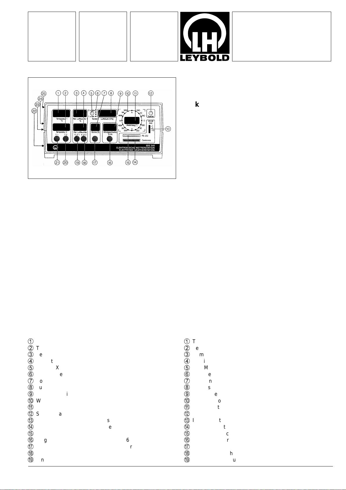
LEYBOLD 666 348 User manual

Physik Chemie ⋅Biologie Technik LEYBOLD DIDACTIC GMBH
7/94-Mü-
Gebrauchsanweisung 666 348
Instruction Sheet 666 349
Scope of supply 666 348
1 Electronic weather station
2 Temperature sensors (lead length: 3/10 m)
2 Humidity sensors (lead length: 3/10 m)
1 Light sensor (lead length: 10 m)
1 Software (3 1/2" and 5 1/4" disk) for MS-DOS computer (in
German, English, French and Spanish)
Scope of supply 666 349
1 Wind speed sensor
1 Wind direction sensor
1 Stainless-steel supporting rod
1 Connection lead for weather station (length: 20 cm)
1 Areas of application
The microprocessor-controlled weather station can record and
display eight different parameters for weather observation. The
software included in the scope of supply allows you to save
measured values and evaluate them graphically using an MS-
DOS computer. In addition, the measured values can also be
output to a printer at adjustable time intervals.
2 Description
1
Temperature display 1
2
Temperature display 2
3
Humidity display 1
4
Humidity display 2
5
MIN-MAX key
6
Barometric pressure tendency indicator
7
Sunshine period display
8
Air pressure display
9
Wind speed display
A
Compass rose
B
Wind direction display
C
Storage key
D
Interval switch for printer output
E
Centronics interface (parallel)
F
RS 232 interface (serial)
G
Input socket for wind sensor 666 439
H
Input socket for sunshine sensor
I
Input socket for humidity sensor 2
J
Input socket for humidity sensor 1
Lieferumfang 666 348
1 Elektronische Wetterstation
2 Temperaturfühler (Kabellänge: 3/10 m)
2 Feuchtefühler (Kabellänge: 3/10 m)
1 Lichtsensor (Kabellänge: 10 m)
1 Software (3 1/2" und 5 1/4" - Diskette) für MS-DOS-Rech-
ner (in Deutsch, Englisch, Französisch, Spanisch)
Lieferumfang von 666 349
1 Windgeschwindigkeits-Aufnehmer
1 Windrichtungsaufnehmer
1 VA-Trägerrohr
1 Verbindungskabel zur Wetterstation (Länge: 20 cm)
1 Einsatz/Anwendung
Die mikroprozessorgesteuerte Wetterstation kann acht Para-
meter zur Wetterbeobachtung aufnehmen und anzeigen. Mit
der beiliegenden Software und einem MS-DOS-Computer ist
die Speicherung und grafische Auswertung der Meßwertemög-
lich. Weiterhin können mit einem Drucker die Meßwerte in ein-
stellbaren Zeitintervallen ausgedruckt werden.
2 Gerätebeschreibung
1
Temperaturanzeige 1
2
Temperaturanzeige 2
3
Feuchteanzeige 1
4
Feuchteanzeige 2
5
MIN-MAX-Taste
6
Luftdrucktendenzanzeige
7
Sonnenscheindaueranzeige
8
Luftdruckanzeige
9
Windgeschwindigkeitsanzeige
A
Windrose
B
Windrichtungsanzeige
C
Speichertaste
D
Intervallschalter für Druckerausgabe
E
Centronics-Schnittstelle (parallel)
F
RS 232-Schnittstelle (seriell)
G
Eingangsbuchse für Windaufnehmer 666 439
H
Eingangsbuchse für Sonnenscheindaueraufnehmer
I
Eingangsbuchse für Feuchtefühler 2
J
Eingangsbuchse für Feuchtefühler 1
Elektronische Wetterstation
Wind-Meßaufnehmer
Electronic Weather Station
Wind Sensor

K
Eingangsbuchse für Temperaturfühler 2
L
Eingangsbuchse für Temperaturfühler 1
M
Hauptschalter (auf der Rückseite)
N
Netzspannungsversorgung mit Sicherung (auf der Rückseite)
O
PROG. - Taste (auf der Rückseite)
P
KALIB. - Taste (auf der Rückseite)
3 Funktionsweise
Die Meßwerte werden nacheinander vom Mikroprozessor gele-
sen, linearisiert und angezeigt. Weiterhin werden ständig die
MIN- und MAX-Werte gespeichert und können über die Taste
5
angezeigt werden.
Über die RS 232-Schnittstelle (seriell) werden die Meßwerte
ständig und über die Centronics-Schnittstelle in einstellbaren
Intervallen ausgegeben.
4 Inbetriebnahme
Meßfühler und Wind-Meßaufnehmer an die Buchsen
G
-
L
an-
schließen. Netzkabel mit Netzeingang
M
verbinden und Gerät
mit Schalter
N
einschalten.
Achtung:
Bei Außenmessungen sind die Temperatur-, Feuchte- und
Sonnenscheindauer-Fühler gegen Regen zu schützen.
5 Funktionsbeschreibung
5.1 Temperaturmessung
Die Temperaturfühler werden gemäß Kennzeichnung an die
Buchsen
K
und
L
angeschlossen. Bei Außentemperaturmes-
sung ist der Fühler gegen direkte Sonneneinstrahlung und ge-
gen Regen zu schützen. Die Messung erfolgt an der Fühlerspit-
ze; die Meßdaten werden auf den Displays
1
und
2
ange-
zeigt.
5.2 Feuchtemessung
Die Feuchtefühler werden gemäß Kennzeichnung an Buchse
I
und
J
angeschlossen. Um genaue Messungen zu erzielen,
muß der Feuchtraumfühler in der Nähe des Temperaturfühlers
moniert werden. Bei der Umrechnung in % rel. Luftfeuchte wird
automatisch die Temperatur berücksichtigt. Bei Außenmontage
ist der Fühler gegen direkte Sonneneinstrahlung und gegen
Regen zu schützen. Die Anzeige erfolgt auf den Displays
3
und
4
.
5.3 Messung der Sonnenscheindauer
Der Fühler wird an Buchse
H
angeschlossen und ist in Rich-
tung der Mittagssonne zu montieren.
Die Sonnenscheindauer wird mit einer Auflösung von 0,1 Std.
bis zu einer Gesamtdauer von 10 Std. angezeigt.
Ab 10 Std. erfolgt eine automatische Umschaltung zu einer Auf-
lösung von 1 Std.
Das Ergebnis der Sonnenscheindauermessung wird jeweils
abends gespeichert und am nächsten Morgen gelöscht, so daß
die Zählung bei Null beginnt. Durch Betätigen des Tasters
5
erscheint das Ergebnis des Vortages.
5.4 Messung der Windgeschwindigkeit und -richtung
Der Windmeßaufnehmer 666 349 wird an Buchse (
G
ange-
schlossen und ist an einer freien Stelle z. B. einige Meter ober-
halb des Hausdaches an einem Antennenmast zu montieren.
Der Mast muß geerdet werden (VDE-Vorschriften einhalten)
und die Statik ist zu beachten. Die Arbeiten sollten nur von ei-
nem Fachmann durchgeführt werden.
Der Windrichtungsanzeiger mußeinmalig ausgerichtet werden.
Die Spitze muß hierbei nach Norden ausgerichtet bleiben; das
Vierkant-Trägerrohr wird solangeam Mast gedreht, bis auf dem
Display
B
0 Grad erscheint. Dazu wird der Windrichtungsan-
zeiger bei eingeschalteter Wetterstation einmal um 360° ge-
K
Input socketfor temperaturesensor 2
L
Input socketfor temperaturesensor 1
M
Main switch (on rear of device)
N
Mains power supply with fuse (on rear of device)
O
PROG. key (on rear of device)
P
CALIB. key (on rear of device)
3 Function
The microprocessor reads, linearizes and displays the measu-
red values one after another. In addition, the MIN and MAX va-
lues are continually saved and can be displayed using key
5
.
The measured values are output continuously via the RS 232
(serial) interface and at an adjustable interval via the Centro-
nics (parallel) interface.
4 Putting into operation
Connect the measuring sensors and wind sensor to sockets
G
through
L
. Connect the power lead to mains input
M
and
switch on the device with switch
N
.
Attention:
Protect the temperature, humidity and sunshine period sensors
from rain when measuring out of doors!
5 Description of function
5.1 Temperature measurement
The temperature sensors are connected to sockets
K
and
L
according to the respective designations. When measuring the
outdoor temperature, the sensor must be protected from direct
sunshine and rain. The measuring point is the tip of the sensor;
measurement data appear on the displays
1
and
2
.
5.2 Humidity measurement
The humidity sensors are connected to sockets
I
and
J
according to the respective designations. In order to obtain
accurate measurements, the humidity sensor mustbe mounted
near the temperature sensor. The temperature is automatically
taken into consideration in converting to percent relative
humidity. When measuring out of doors, the sensor must
be protected from direct sunshine and rain. The measurement
data appear on the displays
3
and
4
.
5.3 Measuring the sunshine period
The sensor is connected to socket
H
so that it points toward the
position of the sun at midday.
The sunshine period is displayed with a resolution from 0.1
hours up to a total period of 10 hours.
Above 10 hours, the device automatically switches to a re-
solution of 1 hour.
The result of the sunshine period measurement is stored every
evening and reset the next morning, so that the count begins
again at zero. Pressing the key
5
displays the result of the
previous day.
5.4 Measuring wind speed and direction
The wind sensor 666 349 is connected to socket (
G
and should
be mounted at a free site e.g. several meters above the rooftop
on an antenna mast.
The mast must be grounded (observe VDE regulations or your
equivalent local regulations); make sure that the mast and roof-
top can bear the additional load. Installation should only be
carried out by a trained service person.
The wind direction sensor must be adjusted only once. Its tip
must point toward true (geographic) north: the square
supporting rod is turned on the mast untilthe display
B
reads 0
degrees. Next, while the weather station is switched on, the
2

dreht und danach die Spitze nach Norden ausgerichtet. Danach
ist die Windmeßeinrichtung betriebsbereit.
Die Windrichtung wird auf dem Display
B
mit einer Auflösung
von 10 Grad und auf der Windrose
A
mit einer Auflösung von
22,5 Grad angezeigt. Auf Display
9
wird die Windgeschwindig-
keit in m/sec angezeigt. Die Windrichtungs- und Windge-
schwindigkeitsaufnehmer besitzen eine elektrische Heizung,
so daß sich kein Kondenswasser bilden kann und ein Betrieb
bis -40°C möglich ist.
5.5 Luftdruckmessung
Der Luftdruck wird auf dem Display
8
in hPa angezeigt. Es
wird der tatsächliche Luftdruck am Aufstellungsort gemessen.
Liegt der Aufstellungsort oberhalb der Meereshöhe, so kann
eine Höhenkorrektur bis 2000 m erfolgen (s. Abgleich und Pro-
grammierung).
Über vier Leuchtdioden
6
erfolgt eine Luftdrucktendenzanzei-
ge. Hierbei wird zwischen "langsam" (eine LED an) oder
"schnell" (zwei LEDs an) steigendem oder fallendem Luftdruck
unterschieden. Bei konstantem Luftdruck sind die LEDs erlo-
schen.
5.6 RS 232-Schnittstelle
Die Wetterstation kann mit dem Anschlußkabel 667 931 (an
beiden Enden eine 25-polige Buchse, Pins 2-3, 4-5, 6-20 sind
gekreuzt) an die serielle Schnittstelle eines Computers (Be-
triebssystem: MS-DOS ab Version 3.20) angeschlossen wer-
den. Mit der beiliegenden Software können die Meßwerte er-
faßt und grafisch dargestellt werden.
5.7 Centronics-Schnittstelle
An die Buchsenleiste
E
kann mit Hilfe des Kabels 728 069 ein
Drucker angeschlossen werden. Die Meßwerte können in ein-
stellbaren Intervallen (mit Schiebeschalter
D
) ausgedruckt
werden.
5.8 MIN-MAX-Werte
Durch einmaliges Betätigen des Tasters
5
werden die Mini-
malwerte und durch ein weiteres Betätigen des Tasters die Ma-
ximalwerte des vorangegangenen Tages angezeigt. Zusätzlich
leuchten die unteren bzw. oberen LEDs
6
der Tendenzanzei-
ge. Nach der letzten Tastenbetätigung gehtdie Wetterstation in
den aktuellen Meß- und Anzeigemodus zurück.
6 Abgleich und Programmierung
Die Meßwertaufnehmer (Temperatur, Feuchte, Sonnenschein-
dauer) müssen bei Sensortausch bzw. bei Ersatzteilbeschaf-
fung neu kalibriert werden. Hierzu stehen zwei verschiedene
Abgleichmöglichkeiten zur Verfügung.
1. Zahlencode-Abgleich
Alle Sensoren sind werkseitig ausgemessen; deshalb liegen je-
dem Temperatur-, Feuchte- und Sonnenscheindauerfühler je-
weils zwei vierstellige Zahlencodes bei, die die exakten Ab-
gleichdaten repräsentieren. Zur Eingabe der Zahlencodes wer-
den die rückseitigen Tasten PROG
O
und KALIB
P
für minde-
stens 3 Sekunden gleichzeitig gedrückt - die Wetterstation wird
dadurch in den Kalibriermodus geschaltet; im Display "Windge-
schwindigkeit"
9
wird dies durch
C1
(
C2
= Individualabgleich)
angezeigt. Eine kurze Betätigung der rückseitigen Taste KALIB
P
schaltet zwischen
C1
(Zahlencodeabgleich) und
C2
(Indivi-
dualabgleich) um.
wind direction sensor is turned through 360 ° and then the tip is
once again aligned with true north. The wind sensor is now
ready for operation.
The wind direction is shown on the display
B
with a resolution
of 10 degrees and on the compass rose
A
with a resolution of
22.5 degrees. The display
9
shows the wind speed in m/sec.
The wind direction and wind speed sensors are equipped with
electric heating, so that no water condensation can occur and
the system can operate reliably at temperatures as low as -40°C.
5.5 Air pressure measurement
The air pressure is shown on the display
8
in hPa. The system
measures the actual air pressure at the measuring site. If the
measuring site is above sea level, the you can correct for an
altitude of up to 2000 m (see section "Calibrating and configu-
ring the weather station").
The tendency of the air pressure is indicated by four LEDs
6
.
The indicator distinguishes between "slow" (one LED on) or
"fast" (two LEDs on) increases or decreases in air pressure. At
a constant air pressure all LEDs are extinguished.
5.6 RS 232 interface
The weather station can be connected to the serial interface of
an MS-DOS computer (DOS version 3.20 or higher) by means
of the connection cable for computers 667 931 (25-pin sub-D
socket at each end, pins 2-3, 4-5, 6-20 crossed). The software
included in the scope of supply enables you to record and
graphically display the measured values.
5.7 Centronics interface
Using the PC printer cable 728 069,you can connect the device
to a printer via the connector
E
. You can print out the measured
values at adjustable intervals (set via slide switch
D
).
5.8 MIN-MAX values
Pressing the key
5
once displays the previous day’s minimum
values; pressing it twice displays the corresponding maximum
values. In addition, the top or bottom LEDs
6
of the tendency
indicator light up. After the last key press, the weather station
returns to the current measuring and display mode.
6 Calibrating and configuring the weather station
The measurement sensors (temperature, humidity, sunshine
period) must be recalibrated every time sensors are exchanged
or old sensors replaced. You can use one of two calibration
methods.
1. Numeric code calibration
All sensors are factory tested; thus, every temperature, humidity
and sunshine period sensor is supplied with two four-digit
numeric codes, which represent the exact calibration data. To
enter the numeric codes, hold down the PROG
O
and CALIB
P
keys (located on the rear of the device) at the same time for at
least three seconds. This activates the weather station’s cali-
bration mode. The display "Wind speed"
9
indicates this by
showing the message
C1
(
C2
= individual calibration). Pressing
the key CALIB
P
on the rear of the device toggles between
C1
(numeric code calibration) and
C2
(individual calibration).
3

Die den Fühlern beiliegenden Zahlencodes entsprechen den
Werten für den Offset- bzw. Verstärkungseinstellung und durch
1,2,3 ... die Meßstelle im Display "Windrichtung"
B
angezeigt.
Durch kurze Betätigung der rückseitigen Taste PROG
O
, wird
zwischen
n
(Offset),
U
(Verstärkung) und 1,2,3 ... (Meßstelle)
umgeschaltet (
n2
bedeutet beispielsweise: Offset-Einstellung
der Meßstelle 2).
Die Meßstellen sind folgendermaßen zugeordnet:
1 - Temperatur 1
2 - Temperatur 2
3 - Rel. Luftfeuchte 1
4 - Rel. Luftfeuchte 2
5 - Luftdruck
6 - Schaltpunkt für Sonnenscheindauer
Die Zahlencodes werden auf dem Display "Luftdruck"
8
ange-
zeigt und können mit der MIN-MAX-Taste
5
vergrößert und mit
der Speichertaste
C
verkleinert werden.
Nach Eingabe der beiden zum Sensor gehörigen Zahlencodes
werden diese durch Drücken der rückseitigen Taste PROG
O
für mindestens 3 Sekunden (!) gespeichert. Bei der Speiche-
rung bleiben alle anderen Werte unbeeinflußt, so daß dieser
Vorgang für jede Meßstelle einzeln durchführbar ist.
Beispiel: Kalibrierung des Feuchtesensors 2
1. PROG
O
und KALIB-Taste
P
gleichzeitig ca. drei Sekun-
den drücken.
2. Taste PROG
O
solange kurzzeitig drücken bis auf dem
Display "Windrichtung"
B
n4 erscheint.
3. Mit den Tasten MIN-MAX
5
bzw. Speicher
C
die Anzeige
auf dem Display "Luftdruck"
8
so verändern, daß sie mit
dem Offset-Zahlencode des Feuchtefühlers überein-
stimmt.
4. Taste PROG
O
einmal kurz betätigen - im Display "Wind-
richtung"
B
erscheint U4.
5. Verstärkungs-Zahlencode, wie unter 3. beschrieben, ein-
geben.
6. PROG
O
ca. drei Sekunden drücken bis die Anzeige im
Display "Luftdruck"
8
erlischt. Die neuen Abgleichdaten
sind jetzt dauerhaft gespeichert.
7. Durch zweimaliges Drücken der Taste KALIB
P
schaltet
die Wetterstation in den allgemeinen Anzeigemodus.
2. Individueller Abgleich
Hierbei wird jeder Meßfühler mittels zweier Abgleichpunkte
(z. B. 0 °C und 40 °C bei Temperaturfühlern) kalibriert.
Hierzu muß der Kalibriermodus C2 im Display "Windgeschwin-
digkeit"
G
aufgerufen werden. (vgl. 1. Zahlencodeabgleich).
Die beiden Abgleichpunkte werden im Display "Temperatur 1"
1
mit den Tasten MIN-MAX
5
und Speichern
C
eingestellt.
Beispiel: Kalibrierung des Temperatursensors 2
1. PROG-
O
und KALIB-Taste
P
gleichzeitig mindestens
drei Sekunden drücken.
2. Taste KALIB
P
einmal betätigen - auf dem Display "Wind-
geschwindigkeit"
G
erscheint C2.
3. Taste PROG
O
solange kurzzeitig betätigen bis auf dem
Display "Windrichtung"
B
n2 erscheint.
4. Fühler ins Eiswasser tauchen und ca. eine Minute warten.
Danach Anzeige im Display "Temperatur 1" mit Hilfe der
Tasten MIN-MAX
5
bzw. Speicher
C
auf 0.0 einstellen.
5. Taste PROG
O
einmal drücken, im Display "Windrich-
tung"
B
erscheint U2.
6. Fühler in ca. 40 °C warmes Wasser tauchen.
7. Wassertemperatur mit einem geeichten Thermometer (z.
B. Fieberthermometer) exakt messen und mit Hilfe der Ta-
sten MIN-MAX
5
und Speicher
C
im Display "Tempera-
tur 1"
1
einstellen.
8. PROG-Taste
O
mindestens drei Sekunden drücken bis
die Anzeige im Display "Luftdruck"
8
erlischt. Die neuen
Abgleichdaten sind jetzt dauerhaft gespeichert.
9. Durch einmaliges Drücken der Taste KALIB
P
schaltet
die Wetterstation in den aktuellen Anzeigemodus.
The numeric codes supplied with the sensors correspond to the
values for the offset and gain settings, and the respective
measurement sensor site is indicated by the numbers 1,2,3 ...
in the display "Wind direction"
B
. Pressing the PROG key
O
,
on the rear of the device toggles between
n
(offset),
U
(gain)
and 1,2,3 ... (sensor site) (for example,
n2
means the offset
setting for sensor site 2).
The sensor site numbers are assigned as follows:
1 - temperature 1
2 - temperature 2
3 - relative humidity 1
4 - relative humidity 2
5 - air pressure
6 - switching point for sunshine period
The numeric codes appear in the display "Air pressure"
8
; you
can increase the displayed value by pressing the MIN-MAX key
5
and decrease it by pressing the storage key
C
.
After entering the two numeric codes for the respective sensor,
store them by holding down the PROG key
O
on the rear of the
device for at least three seconds (!). Storage has no effect on
the other stored values, so that you can calibrate each sensor
site individually.
Example: calibrating humidity sensor 2
1. Hold down the PROG key
O
and the CALIB key
P
at the
same time for at least three seconds.
2. Press the PROG key
O
repeatedly until the display "Wind
direction"
B
reads n4.
3. Using the MIN-MAX
5
and storage
C
keys, change the
value in the display "Air pressure"
8
so that it agrees with
the offset-numeric code of the humidity sensor.
4. Briefly press PROG
O
once more - U4 appears in the
display "Wind direction"
B
.
5. Enter the numeric code for gain as described under point
3.
6. Hold down the PROG
O
key for approx. three seconds,
until the value in the display "Air pressure"
8
disappears.
The new calibration data are now permanently stored.
7. Return the weather station to standard display mode by
pressing the CALIB key
P
twice.
2. Individual calibration
In this calibration mode, each measuring sensor is calibrated
on the basis of two calibration points (e.g. 0 °C and 40 °C for
temperature sensors).
First, activate calibration mode C2 in the display "Wind speed"
G
(cf. 1. "Numerical code calibration"). The two calibration po-
ints are then entered in the display "Temperature 1"
1
using
the MIN-MAX
5
and storage
C
keys.
Example: calibrating temperature sensor 2
1. Hold down the PROG key
O
and the CALIB key
P
at the
same time for at least three seconds.
2. Press the CALIB key
P
once - C2 appears in the display
"Wind speed"
G
.
3. Press the PROG key
O
repeatedly until the display "Wind
direction"
B
reads n2.
4. Immerse the sensor in ice water and wait for about one
minute. Then set the value in the display "Temperature 1"
to 0.0 using the MIN-MAX
5
and storage
C
keys.
5. Briefly press PROG key
O
once more - U2 appears in the
display "Wind direction"
B
.
6. Immerse the sensor in warm water (approx. 40 °C).
7. Measure the water temperature precisely with a calibrated
thermometer (e.g. fever thermometer) and set this value in
the display "Temperature 1"
1
using the MIN-MAX
5
and
storage
C
keys.
8. Hold down the PROG
O
key for approx. three seconds,
until the value in the display "Air pressure"
8
disappears.
The new calibration data are now permanently stored.
9. Return the weather station to standard display mode by
pressing the CALIB key
P
twice.
4

3. Konfiguration der Wetterstation
Durch Betätigen der PROG-Taste
O
für mindestens drei Se-
kunden wird in den Konfigurationsmodus umgeschaltet. An-
schließend können durch kurzzeitiges Drücken der PROG-Ta-
ste
O
sechs Menüpunkte 1 .. 6 werden im Display "Temperatur
1"
1
und die Kurzbezeichnung im Display "Feuchte 1"
3
ange-
zeigt.
Folgende Menüpunkte sind einstellbar:
Menüpunkt 1 (SPE)
Dient der Einstellung div. Einheiten der Windgeschwindigkeits-
anzeige: 1 - km/h; 2 - m/s; 3 - Knoten; 4 - mph; 5 - Beaufort.
1 ... 5 wird im Display "Luftdruck"
8
angezeigt. Die Ziffern für
die Einheit werden mit der Taste MIN-MAX
5
bzw. Speicher
C
eingestellt.
Menüpunkt 2 (HOE)
Dient zur Höhenkorrektur bei der Luftdruckmessung zwischen
0 ... 2000 m. Die Standorthöhe wird aufdem Display "Luftdruck"
8
angezeigt und kann mit den Tasten MIN-MAX
5
und Spei-
cher
C
verändert werden. Bei Eingabe von 0 m wird der tat-
sächlich am Aufstellungsort herrschende Luftdruck angezeigt.
Liegt der Aufstellungsort oberhalb der Meereshöhe, so wird
durch Eingabe der Höhe der auf Meereshöhe umgerechnete
Druck angezeigt. In diesem Fall ist in der beiliegenden Soft-
ware 0 m für die Höhe einzusetzen (s. Anleitung zum Compu-
terprogramm)
Menüpunkt 3 (DRU)
Ohne Funktion
Menüpunkt 4 (SL)
Dient zur Einstellung der Zeilenzahl pro Druckseite zwischen
20 und 80 Zeilen.
Menüpunkt 5 (SIO)
Bei diesem Menüpunkt muß auf dem Display "Luftdruck"
8
eine 2eingestellt sein.
Menüpunkt 6
Dient zur Einstellung der Baud-Rate. Bei Einsatz der beiliegen-
den Software muß derWert auf 9600 Baud eingestellt werden.
Nach Einstellung der Menüpunkte werden durch Drücken der
Taste PROG
O
für mindestens drei Sekunden alle Einstellun-
gen gespeichert. Nach der Speicherung schaltet die Wettersta-
tion automatisch in den aktuellen Anzeigemodus.
4. Manuelle Speicherintervalle
Mit Hilfe der Speichertaste
C
und der rückseitigen PROG-Ta-
ste
O
können individuelle Speicherintervalle eingestellt wer-
den. Der Startzeitpunkt für den Beginn des zu speichernden
Zeitraumes wird durch gleichzeitiges Betätigen der Tasten
Speicher
C
und PROG
O
festgelegt, wobei die Tasten minde-
stens zwei Sekunden lang gedrückt werden müssen. Die Mini-
mum-Werte können anschließend durch Betätigen der Taste
Speicher
C
angezeigt werden. Durch nochmalige Betätigen
der Taste werden die Maxima angezeigt. Bei dritter Betätigung
der Taste
C
schaltet die Wetterstation in den aktuellen Anzei-
gemodus zurück (automatisch, falls innerhalb einer Minute kein
weiterer Tastendruck erfolgt). Die untere LED der Tendenzan-
zeige
6
markiert die Minimum-Werte und die obere LED
6
die
Maximum-Werte. Auf dem Display "Windrichtung"
B
erscheint
die Anzahl der vergangenen Tage seit Start. Bei der Sonnen-
scheindauer wird beim Aufruf der Minimum-Werte die kürzeste
Gesamtsonnenscheindauer eines Tages innerhalb des Spei-
cherzeitraums angezeigt, analog erfolgt die Anzeige beim Auf-
ruf der Maximum-Werte.
Das Speicherintervall wird durch gleichzeitiges Betätigen der
Speichertaste
C
und der PROG-Taste
O
beendet; gleichzeitig
wird ein neues Intervall gestartet, wobei die alten Minimum-
und Maximum-Werte gelöschtwerden.
3. Configuring the weather station
Hold down the PROG key
O
for at least three seconds to acti-
vate configuration mode. You can then browse through the six
menu points 1 ... 6 in the display "Temperature 1"
1
and the
corresponding designation in the display "Humidity 1"
3
by
pressing the PROG key
O
repeatedly.
You can configure the system using the following menu points:
Menu point 1 (SPE)
Selects the unit for wind speed display: 1 - km/h; 2 - m/s; 3 -
knots; 4 - mph; 5 - Beaufort.
1 ... 5 appears in the display "Air pressure"
8
. Set the numbers
for the respective units with the MIN-MAX
5
and storage
C
keys.
Menu point 2 (HOE)
For altitude correction of air pressure measurement between
0 ... 2000 m. The measuring site altitude appears in the display
"Air pressure"
8
and can be changed with the MIN-MAX
5
and
storage
C
keys. Selecting 0 m sets the display to the actual air
pressure at the measuring site. If the measuring site is above
sea level, input of the altitude results in the display of air
pressure compensated for altitude. In this case, set the altitude
in the software to 0 m (see software instruction sheet).
Menu point 3 (DRU)
No function
Menu point 4 (SL)
Sets the number of lines per printed page to any value between
20 and 80 lines.
Menu point 5 (SIO)
In this menu point, the value 2must be set on the display "Air
pressure"
8
.
Menu point 6
For setting the baud rate. The software "Weather" requires a
value of 9600 baud.
When you have made all the desired settings, you can save all
settings by pressing the PROG key
O
for at least three
seconds. Once the values have been saved, the weather station
automatically switches to the current display mode.
4. Manual storage intervals
Using the storage key
C
and the PROG key
O
on the rear of
the device, you can set individual storage intervals. The storage
period is started by pressing the storage
C
and PROG
O
keys
at the same time and holding them down for at least two
seconds. The minimum values can then be displayed by pres-
sing the storage key
C
. Pressing this key again displays the
maxima. The weather station returns to the current display
mode the third time you press the key
C
(or automatically if no
other key is pressed within one minute). The bottom LED of the
tendency indicator
6
lights up for the minimum values and the
top LED
6
lights up for the maximum values. The display "Wind
direction"
B
shows the number of days elapsed since the start
of measuring. In the case of the sunshine period, the minimum
value is the shortest total sunshine period for one day within the
storage period; the maximum value is defined in the correspon-
ding manner.
The storage interval is terminated by pressing the storage key
C
and the PROG key
O
simultaneously; at the same time, this
also starts a new storage interval, and the old minimum and
maximum values are deleted.
5

7 Technische Daten 666 348
•2 Temperaturmeßstellen
-40°C ... + 100°C
Auflösung: 0,1 K
Meßgenauigkeit: ± 0,3 K
Anzeige: 3-stellig (7-Segment)
Ziffernhöhe: 13 mm
Eingänge: 2 Diodenbuchsen, 5-polig
•2 Feuchtemeßstellen
Meßbereich: 0 ... 100% rel. Feuchte
Temperaturbereich: -25°C ... +85°C
Auflösung: 0,1% rel. Feuchte
Meßgenauigkeit: 2% bei Raumtemperatur
Anzeige: 3-stellig (7-Segment)
Ziffernhöhe: 13 mm
Eingänge: 2 Diodenbuchsen, 5 pol.
•Luftdruckanzeige
Meßbereich: 800 ... 1200 hPa
Auflösung: 1 hPa
Meßgenauigkeit: 2 hPa
Anzeige: 3 1/2-stellig (7-Segment)
Ziffernhöhe: 13 mm
Luftdrucksensor im Gerät eingebaut
•Luftdrucktendenzanzeige über vier Leuchtdioden
•Sonnenscheindaueranzeige
(Schaltpunkt: 10 kLux
=
n6 = 5000, u6 = 4000)
(Schaltpunkt 5 kLux
=
n6 = 5000, u6 = 8000)
(Schaltpunkt 20 klux
=
n6 = 5000, u6 = 2000)
Meßbereich: 0 ... 24 h
Auflösung: 0,1 h (< 10 h); 1,0 h (>10 h)
Anzeige 2-stellig (7-Segment)
Ziffernhöhe: 13 mm
•Windgeschwindigkeitsanzeige
Meßbereich: 1 ... 30 m/s (
=
ca. 12 Beaufort)
Auflösung: 0,1 m/s
Meßgenauigkeit: ±0,2 m/s
Anzeige: 3-stellig (7-Segment)
Ziffernhöhe: 13 mm
Eingang: Diodenbuchse, 8-pol.
•Windrichtungsanzeige
Meßbereich: 0 ... 360 °
Auflösung: 10 °
Meßgenauigkeit: 10 °
Anzeige: 3-stellig (7-Segment)
Ziffernhöhe: 13 mm
Eingang: Diodenbuchse, 8-pol.
•Windrose über 16 Leuchtdioden
Auflösung: 22,5 °
•Automatische Speicherung der täglichen MIN- und MAX-
Werte
•wählbarer individueller Zeitraum zum Speichern der MIN-
und MAX-Werte
•Meßfühlertausch durch digitales Abgleichverfahren möglich
•RS 232 C-Schnittstelle zur Datenausgabe auf Computer
•Centronics-Schnittstelle zur Datenausgabe auf Drucker,
Ausgabeintervall einstellbar (1, 5, 10 und 60 min)
•Spannungsversorgung: 220 V
"
, 50 Hz
•Abmessungen: 300 x 140 x 230 mm
•Gewicht: 3 kg
7 Technical data 666 348
•2 Temperature measurement points
-40°C ... + 100°C
Resolution: 0.1 K
Measurement accuracy: ± 0.3 K
Display: 3 digits (7-segment)
Digit height: 13 mm
Inputs: 2 DIN sockets, 5-pin
•2 Humidity measurement points
Measuring range: 0 ... 100% relative humidity
Temperature range: -25°C ... +85°C
Resolution: 0.1% relative humidity
Measurement accuracy: 2% at room temperature
Display: 3 digits (7-segment)
Digit height: 13 mm
Inputs: 2 DIN sockets, 5-pin
•Air pressure display
Measuring range: 800 ... 1200 hPa
Resolution: 1 hPa
Measurement accuracy: 2 hPa
Display: 3 1/2 digits (7-segment)
Digit height: 13 mm
Barometric pressure sensor integrated in device
•Barometric pressure tendency indicated by means of four
LEDs
•Sunshine period display
(Switching point: 10 kLux
=
n6 = 5000, u6 = 4000)
(Switching point 5 kLux
=
n6 = 5000, u6 = 8000)
(Switching point 20 kLux
=
n6 = 5000, u6 = 2000)
Measuring range: 0 ... 24 h
Resolution: 0.1 h (< 10 h); 1.0 h (>10 h)
Display: 2 digits (7-segment)
Digit height: 13 mm
•Wind speed display
Measuring range: 1 ... 30 m/s (
=
approx. 12 Beaufort)
Resolution: 0.1 m/s
Measurement accuracy: ±0.2 m/s
Display: 3 digits (7-segment)
Digit height: 13 mm
Input: DIN socket, 8-pin
•Wind direction display
Measuring range: 0 ... 360 °
Resolution: 10 °
Measurement accuracy: 10 °
Display: 3 digits (7-segment)
Digit height: 13 mm
Input: DIN socket, 8-pin
•Compass rose, 16 LEDs
Resolution: 22.5 °
•Automatic storage of daily MIN and MAX values
•Adjustable individual interval for storing MIN and MAX valu-
es
•Digital calibration method for fast and easy exchange or re-
placement of measuring sensors
•RS 232 C interface for outputting data to computer
•Centronics interface for outputting data to a printer, with ad-
justable output interval (1, 5, 10 and 60 min)
•Voltage supply: 220 V AC, 50 Hz
•Dimensions: 300 x 140 x 230 mm
•Weight: 3 kg
6

LEYBOLD DIDACTIC GMBH ⋅Leyboldstrasse 1 ⋅D-50354 Hürth ⋅Phone (02233) 604-0 ⋅Telefax (02233) 604-222 ⋅ Telex 17 223 332 LHPCGN D
©by LeyboldDidacticGmbH, PrintedintheFederalRepublicofGermany
Technical alterations reserved
8 Montageanleitung für Wind-Meßaufnehmer
666 349
Windrad mit Unterlegscheibe auf Windgeschwindigkeitsauf-
nehmer setzen und mit beiliegender M4-Mutter verschrauben.
Die Mutter muß anschließend mit einem Schlitzschraubendre-
her, der von oben in die Welle gesteckt wird, festgezogen wer-
den. Der gleiche Vorgang ist für den Windrichtungsanzeiger zu
wiederholen.
8.1 Technische Daten 666 349
•Windgeschwindigkeit: 1 ... 30 m/s
•Windrichtung: 0 ... 360 °
•Abmessungen: 1200 x 200 x 230 mm
•Gewicht: 2,7 kg
9 Computerprogramm "Wetter"
Der Wetterstation liegt ein kostenloses Computerprogramm bei
(5 1/4" und 3 1/2"-Disketten).
Legen Sie die Diskette in das Laufwerk A Ihres Computers ein.
Durch Eintippen des Wortes "Wetter" (deutsch), "weather"
(englisch), "meteo" (französisch) bzw. "clima" (spanisch) und
Drücken der Return-Taste (Eingabe-Taste) wirddas Programm
gestartet.
Sollte nach dem Einschalten Ihres Computers auf dem Bild-
schirm C: > zu lesen sein, müssen Sie vor dem Programmstart
zuerst das Diskettenlaufwerk A aktivieren. Geben Sie hierzu
den Befehl "A:" ein und Drücken anschließend die Eingabe-Ta-
ste (Return-Taste). Anschließend fahren Sie wie vorstehend
beschrieben fort.
Eine ausführliche Beschreibung der Software finden Sie in der
beiliegenden Anleitung Computerprogramm "Wetter".
8 Mounting the wind sensor 666 349
Place the wind wheel with washer on the wind speed sensor
and fasten it with the M4 nut. Then tighten the nut using a
flat-blade screwdriver by turning the top of the shaft. Attach
the wind direction sensor in the same way.
8.1 Technical data 666 349
•Wind speed: 1 ... 30 m/s
•Wind direction: 0 ... 360 °
•Dimensions: 1200 x 200 x 230 mm
•Weight: 2.7 kg
9 Computer software "Weather"
The computer software "Weather" is supplied with the weather
station at no extra charge (5 1/4" and 3 1/2" disks).
Insert the disk in drive A of your computer and start the software
by typing "Wetter" (German), "weather" (English), "meteo"
(French) or "clima" (Spanish) and pressing the Return key.
If your computer boots up to the prompt C: >, you must first
change to disk drive A before you can start the program. To do
this, type "A:" and the press the Return key. Then start "Weather"
as described above.
The enclosed instruction sheet describes the software "Weather"
in more detail.
This manual suits for next models
1
Popular Weather Station manuals by other brands

THOMSON
THOMSON 513630 manual

La Crosse Technology
La Crosse Technology WS-1517 instruction manual

Balance Meteo
Balance Meteo 865373 user manual

La Crosse Technology
La Crosse Technology C85845 user manual

La Crosse Technology
La Crosse Technology C87030 Instructional manual

La Crosse Technology
La Crosse Technology CA84688 Faqs