LG CRNN Series User manual

Multi V Air Conditioner
INSTALLATION MANUAL
INDOOR UNIT
Model No.: CRNN_Series

2
The following should be always observed for safety
• Please report to or take consent by the supply authority before connecting to the system.
• Be sure to read "THE FOLLOWING SHOULD BE ALWAYS OBSERVED FOR SAFETY" before installing the air
conditioner.
• Be sure to observe the cautions specified here as they include important items related to safety.
• The indications and meanings are as follows.
• After reading this manual, be sure to keep it together with the instruction manual in a handy place .
❈The installation parts which are not provided should be purchased.
Could lead to death, serious injury, etc.
Could lead to serious injury in particular environments when operated incorrectly.
WARNING
WARNING
CAUTION
CAUTION
• Incomplete installation could cause injury due to fire, electric shock, the unit
falling or a leakage of water. Consult the dealer from whom you purchased the
unit or special installer.
Do not install it yourself (customer).
• Incomplete installation could cause a personal injury due to fire, electric
shock, the unit falling or a leakage of water.
Perform the installation securely referring to the installation manual.
• Do not connect the ground wire to a gas pipe, water pipe arrester
or telephone ground wire. Defective grounding could cause an
electric shock.
Perform grounding
• If gas leaks and accumulates in the area surrounding the unit,
it could cause an explosion.
Do not install the unit in a place where an inflamma-
ble gas leaks.
• If there is a defect in the drainage/piping work, water could drop
from the unit and household goods could be wet and damaged.
Perform the drainage/piping work securely
according to the installation manual.
• When installed in an insufficient strong place, the unit could fall causing
injured.
Install the unit securely in a place which can bear the
weight of the unit.
• Incomplete connecting and fixing could cause fire.
Use the specified wires to connect the indoor and the
outdoor units securely and attach the wires firmly to the
terminal board connecting sections so the stress of the
wires is not applied to the sections.
Check that the refrigerant gas do not leak after installation
is completed.
Be sure to use the part provided or specified parts for
the installation work.
• If the electrical part cover if the indoor unit and/or the service panel if the out-
door unit are not attached securely, it could result in a fire or electric shock
due to dust, water, etc.
Attach the electrical part cover to the indoor unit and the
service panel to the outdoor unit securely.
• If the capacity of the power circuit is insufficient or there is incomplete electri-
cal work, it could result in a fire or an electric shock.
Perform electrical work according to the installation
manual and be sure to use an exclusive circuit.
• The use of defective parts could cause an injury or leakage of water due to a
fire, electric shock, the unit falling, etc.

3
Contents
Installation of Wall Mounted Type Indoor Unit....................................................................... 4
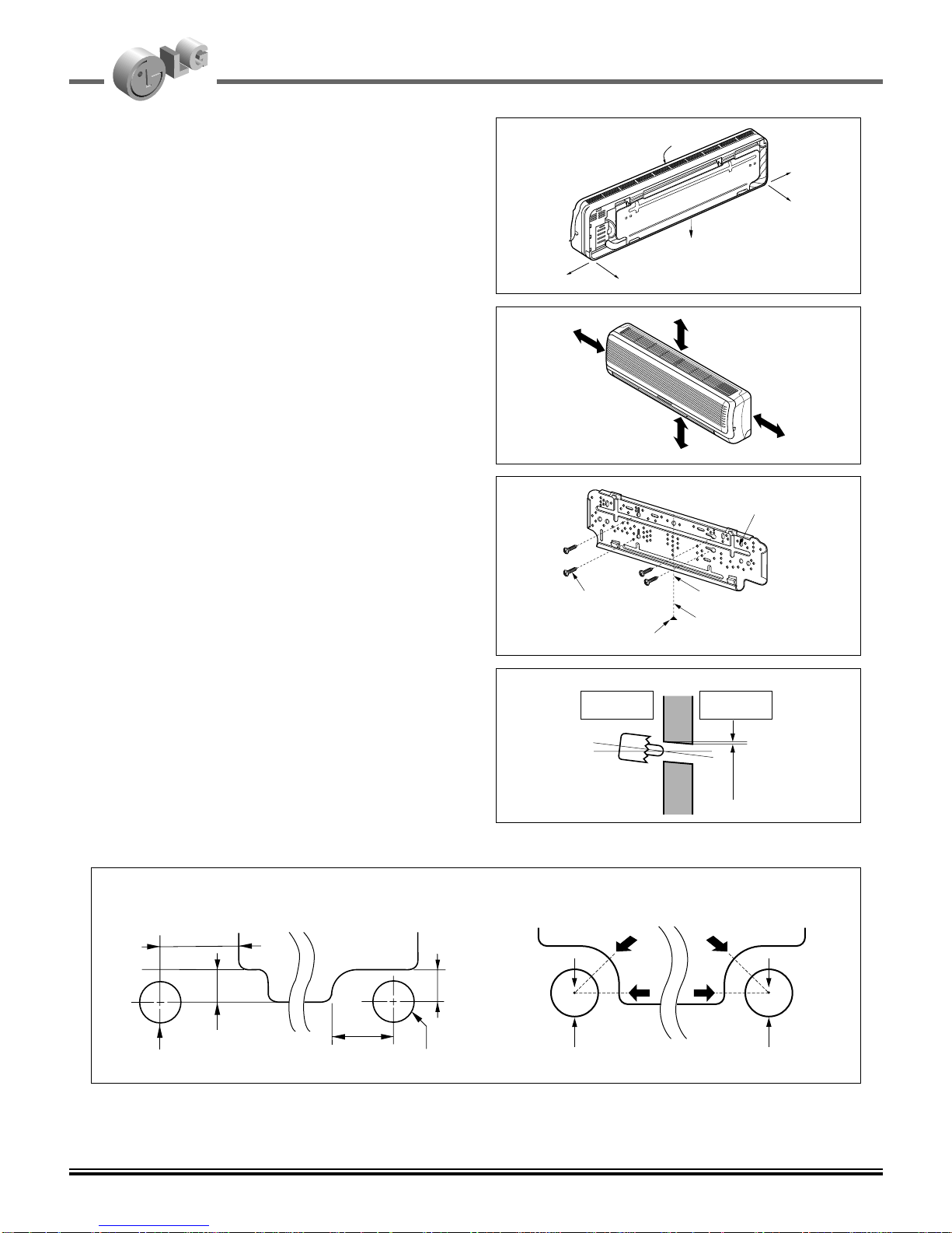
Installation of wall mounted type indoor unit....................................................................................... 4
Selection of the best location.............................................................................................................. 6
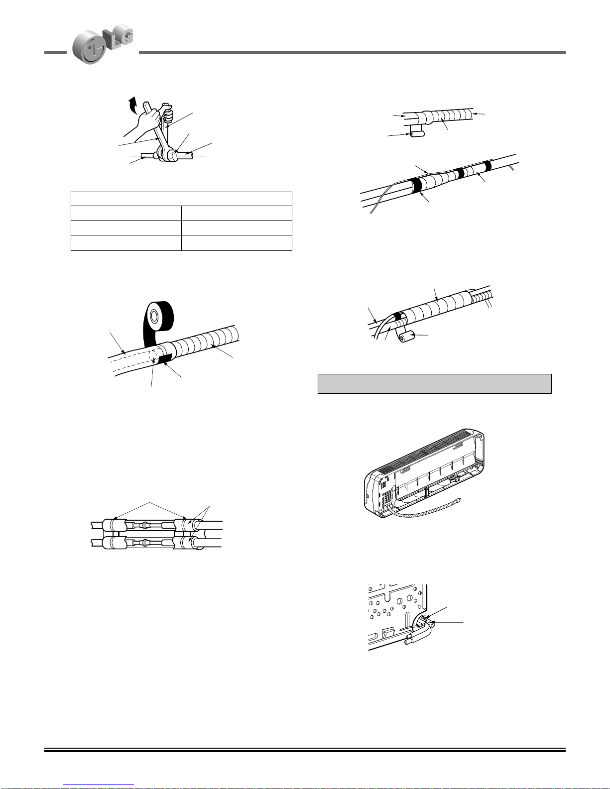
Connection of pipings.......................................................................................................................... 7
Checking the drainage...................................................................................................................... 11
Connect the cable to the indoor unit ................................................................................................. 12
Installation of Art Cool Type Indoor Unit................................................................................ 15
Selection of the best location............................................................................................................ 17
Preparing work for Installation........................................................................................................... 18
Sticking the installation guide map and fixing Indoor unit ................................................................. 19
Preparing work for installation........................................................................................................... 19
Front panel assembly........................................................................................................................ 22
Connect the cable to the Indoor unit................................................................................................. 23
Installation of Ceiling Cassette Type(1 way) Indoor Unit................................................. 25
Selection of the best location............................................................................................................ 27
Ceiling opening dimensions and hanging bolt location..................................................................... 28
The indoor unit installation................................................................................................................ 29
Wiring connection.............................................................................................................................. 30
Installation of decorative panel.......................................................................................................... 31
Indoor unit drain piping...................................................................................................................... 32
Installation of Ceiling Cassette Type(4 way) Indoor Unit................................................. 35
Selection of the best location............................................................................................................ 37
Ceiling opening dimensions and hanging bolt location..................................................................... 38
Wiring connection.............................................................................................................................. 40
Installation of decorative panel.......................................................................................................... 41
Indoor unit drain piping...................................................................................................................... 42
Installation of Convertible Type Indoor Unit......................................................................... 45
Selection of the best location............................................................................................................ 47
Installation......................................................................................................................................... 48
Piping and drainage ......................................................................................................................... 55
Wiring connection.............................................................................................................................. 58
Installation of Ceiling Concealed Duct Type Indoor Unit.................................................. 61
Selection of the best location............................................................................................................ 63
Ceiling dimension and hanging ........................................................................................................ 64
The indoor unit installation................................................................................................................ 65
Connecting cables between indoor unit and outdoor unit................................................................. 66
Checking the drainage...................................................................................................................... 68
Common installation process.................................................................................................... 71
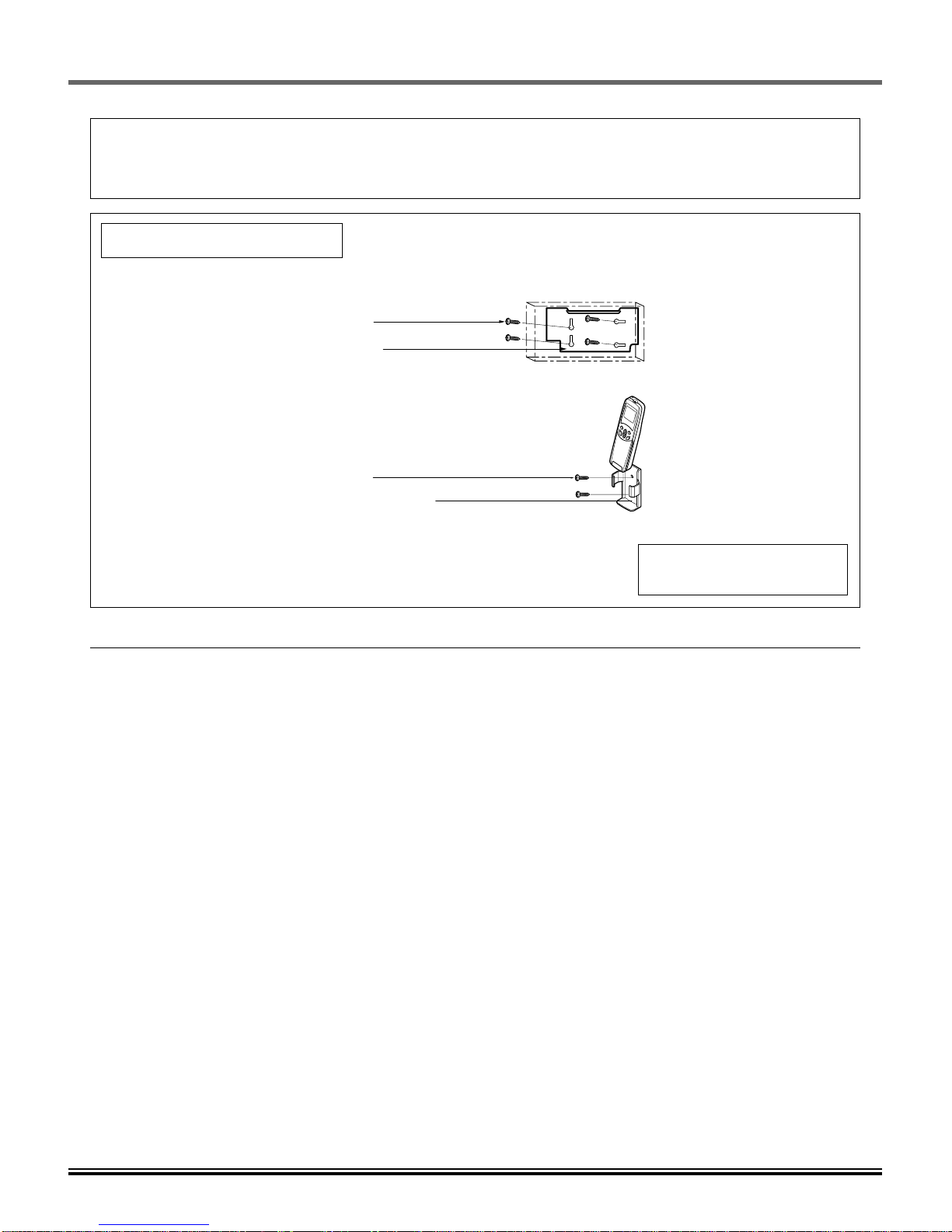
Installation of remote controller......................................................................................................... 71
Preparation of piping......................................................................................................................... 74
Indoor unit drain pipe work................................................................................................................ 77
Installation of drain pump.................................................................................................................. 79
Optional operation............................................................................................................................. 83

Installation of Wall Mounted Type Indoor Unit
4
Installation of Wall Mounted Type Indoor Unit

Installation of Wall Mounted Type Indoor Unit
5
• Please read this instruction sheet completely before installing the product.
• When the power cord is damaged, replacement work shall be performed by authorized personnel only.
• Installation work must be performed in accordance with the national wiring standards by authorized personnel only.
Installation Parts Provided
1. Type "A" screw
2. Installation Plate
3. Type "B" screw
4. Holder Remote Control
Installation of Wall Mounted Type Indoor Unit
Cooling & Heating Model has
included Drain Elbow.
Required Parts Required Tools
❏ Installation plate
❏Four type "A" screws
❏Connecting cable
❏Level gauge
❏Screw driver
❏Electric drill
❏Hole core drill(ø70mm)
❏Pipes: Gas side.....................................Ø12.7, Ø9.53
Liquid side..............................................Ø6.35
(Refer to page 4)
❏Insulation materials
❏Additional drain pipe
(Outer Diameter............................................15.5mm)
❏Flaring tool set
❏Specified torque wrenches
1.8kg.m, 4.2kg.m, 5.5kg.m, 6.6kg.m
(different depending on model No.)
❏Spanner......................................................Half union
❏A glass of water
❏Screw driver
❏Two type "B" screws ❏Owner's manual
❏Thermometer
❏Holder Remote Control

Installation of Wall Mounted Type Indoor Unit
7
Installation of Wall Mounted Type Indoor Unit
■Preparing the indoor unit's piping and drain hose for
installation through the wall.
■Remove the plastic tubing retainer(see illustration
below) and pull the tubing and drain hose away from
chassis.
■Replace the plastic tubing holder in the original position.
1. Route the indoor tubing and the drain hose in the
direction of rear left.
2. Insert the connecting cable into the indoor unit
from the outdoor unit through the piping hole.
■Do not connect the cable to the indoor unit.
■Make a small loop with the cable for easy connection
later.
3. Tape the tubing, drain hose and the connecting
cable. Be sure that the drain hose is located at the
lowest side of the bundle. Locating at the upper
side can cause drain pan to overflow inside the
unit.
NOTE: If the drain hose is routed inside the room, insulate
the hose with an insulation material* so that dripping from
"sweating"(condensation) will not damage furniture or
floors.
*Foamed polyethylene or equivalent is recommended.
4. Indoor unit installation
■Hook the indoor unit onto the upper portion of the
installation plate.(Engage the two hooks of the rear
top of the indoor unit with the upper edge of the
installation plate.) Ensure that the hooks are properly
seated on the installation plate by moving it left and
right.
Press the lower left and right sides of the unit against
the installation plate until the hooks engage into their
slots(clicking sound).
5. Connecting the pipings to the indoor unit and drain
hose to drain pipe.
■Align the center of the pipings and sufficiently tighten
the flare nut by hand.
For left rear piping
CAUTION
When install, make sure that the
remaining parts must be removed
clearly so as not to damage the piping
and drain hose, especially power cord
and connecting cable.
To remove the holder,
press the bottom of
chassis near the holder
upward and pull the tab
out of its hole.
Tubing holder
Pull
Press 2
1
Drain hose
Connecting
cable
Loop
Gas side
piping
Liquid side
piping
Drain hose
Drain hose
Connecting
cable
Indoor unit tubing Flare nut Pipings

Installation of Wall Mounted Type Indoor Unit
6
Installation of Wall Mounted Type Indoor Unit
Front
Right Rear right
Rear left
Down right
Left
Lower than 2.3m
More than 5 cm
Higher than eye-level
More than
5 cm
More than
5 cm
1. Selection of the best location
• There should not be any heat source or steam
near the unit.
• There should not be any obstacles to prevent
the air circulation.
• A place where air circulation in the room will be
good.
• A place where drainage can be easily obtained.
• A place where noise prevention is taken into
consideration.
• Do not install the unit near the door way.
• Ensure the spaces indicated by arrows from
the wall, ceiling, fence, or other obstacles.
The mounting wall should be strong and solid enough
to protect it from the vibration.
1) Mount the installation plate on the wall with
four Type "A" screws.
(If mounting the unit on the concrete wall, consider
using anchor bolts.)
• Always mount the Installation plate horizontally by
aligning the marking-off line by means of the
thread and a level.
2)
Drill the piping hole with 70mm dia. holecore drill.
• Line according to the arrows marked on lower the
left and the rght side of the Installation Plate.
The meeting point of the extended line is the cen-
ter of the hole.
• Drill the piping hole at either the right or the left
and the hole should be slightly slant to the out-
door side.
Installation Plate
marking-off line
Thread
Weight
Type "A" screw
5~7mm
Indoor Outdoor
Wall
ø70mm ø70mm
A
A
A
A
ø70mm ø70mm
50mm
20mm
20mm
80mm
Left rear piping Right rear piping
3.5/18 [kW/Btu]2.1/7, 2.6/9, 3.5/12 [kW/Btu]
The lower left and the right side of Installation Plate

■Tighten the flare nut with a wrench.
■When extending the drain hose at the indoor unit,
install the drain pipe.
6. Wrap the insulation material around the connect-
ing portion.
■Overlap the connection pipe insulation material
and the indoor unit pipe insulation material. Bind
them together with vinyl tape so that there is no
gap.
■Wrap the area which accommodates the rear pip-
ing housing section with vinyl tape.
■Bundle the piping and drain hose together by
wrapping them with vinyl tape over the range with-
in which they fit into the rear piping housing sec-
tion.
1. Route the indoor tubing and the drain hose to the
required piping hole position.
2. Insert the piping, drain hose and the connecting
cable into the piping hole.
Installation of Wall Mounted Type Indoor Unit
8
Installation of Wall Mounted Type Indoor Unit
GAS LIQUID
Ø9.53[4.2kg.m] Ø6.35[1.8kg.m]
Ø12.7[5.5kg.m] Ø6.35[1.8kg.m]
Pipe Size[Torque]
For right rear piping
Torque
wrench
Indoor
unit tubing
Spanner (fixed)
Connection
pipe
Flare nut
Vinyl tape(narrow)
Connection
pipe
Connecting cable
Vinyl tape
(wide) Wrap with vinyl tape
Indoor
unit pipe
Pipe
Wrap with vinyl tape
Drain hose
Pipe
Vinyl tape(wide)
Drain pipe
Connecting cable
Vinyl tape(narrow)
Adhesive
Drain pipe
Indoor unit
drain hose
Plastic bands Insulation material

Installation of Wall Mounted Type Indoor Unit
9
Installation of Wall Mounted Type Indoor Unit
3. Insert the connecting cable into the indoor unit.
■Don't connect the cable to the indoor unit.
■Make a small loop with the cable for easy connec-
tion later.
4. Tape the drain hose and the connecting cable.
•Connecting cable
5. Indoor unit installation
■Hang the indoor unit from the hooks at the top of
the installation plate.
■Insert the spacer etc. between the indoor unit and
the installation plate and separate the bottom of
the indoor unit from the wall.
6. Connecting the pipings to the indoor unit and
the drain hose to drain pipe.
■Align the center of the pipings and sufficiently
tighten the flare nut by hand.
■Tighten the flare nut with a wrench.
■When extending the drain hose at the indoor unit,
install the drain pipe.
7. Wrap the insulation material around the connect-
ing portion.
■Overlap the connection pipe heat insulation and
the indoor unit pipe heat insulation material. Bind
them together with vinyl tape so that there is no
gap.
■Wrap the area which accommodates the rear pip-
ing housing section with vinyl tape.
GAS LIQUID
Ø9.53[4.2kg.m] Ø6.35[1.8kg.m]
Ø12.7[5.5kg.m] Ø6.35[1.8kg.m]
Pipe Size[Torque]
Vinyl tape
Adhesive
Drain hose
Indoor unit drain hose
(narrow)
Plastic bands Insulation material
Vinyl tape
(narrow)
Connection
pipe
Connecting
cable
Indoor
unit piping
Pipe
Vinyl tape
(wide)
Wrap with vinyl tape
Installation plate
Spacer
Indoor unit
8cm
Indoor unit tubing Flare nut Pipings
Torque
wrench
Indoor
unit tubing
Spanner (fixed)
Connection
pipe
Flare nut

Installation of Wall Mounted Type Indoor Unit
10
Installation of Wall Mounted Type Indoor Unit
■Bundle the piping and drain hose together by
wrapping them with cloth tape over the range
within which they fit into the rear piping housing
section.
8. Reroute the pipings and the drain hose across
the back of the chassis.
9. Set the pipings and the drain hose to the back of
the chassis with the tubing holder.
■Hook the edge of tubing holder to tap on chassis
and push the bottom of tubing holder to be
engaged at the bottom of chassis.
10. Indoor unit installation
■Remove the spacer.
■Ensure that the hooks are properly seated on the
installation plate by moving it left and right.
Press the lower left and right sides of the unit
against the installation plate until the hooks engage
into their slots(clicking sound).
Drain hose Vinyl tape
(narrow)
Pipe
Wrap with
vinyl tape(wide)
Drain hose
Connecting
cable
Piping for passage through
piping hole
Tubing holder
Hook
Push
2
1

Installation of Wall Mounted Type Indoor Unit
11
Installation of Wall Mounted Type Indoor Unit
2. Connection of Pipings
1. To remove the front panel from the indoor unit,
remove the front panel from the indoor unit
cabinet.
■Set the air direction louvers up-and-down to the
position(horizontally) by hand.
■Remove the securing screws that retain the front
panel. Pull the lower left and right sides of the
grille toward you and lift it off.
(2.1/7, 2.6/9, 3.5/12 kW/Btu models: 2EA,
3.5/18 kW/Btu models: 3EA)
2. To check the drainage.
■Pour a glass of water on the evaporator.
■Ensure the water flows through the drain hose of
the indoor unit without any leakage and goes out
the drain exit.
Pull the right and
the left side.
Screw

Installation of Wall Mounted Type Indoor Unit
12
Installation of Wall Mounted Type Indoor Unit
Connecting cable
4. Connect the cable to the indoor unit
1) Connect the wires to the terminals on the
control board individually according to the
outdoor unit connection.
•Ensure that the color of the wires of outdoor
unit and the terminal No. are the same as
those of indoor unit respectively.
2) Attach the Grille onto the cabinet.
•Grasp lower the left and right side of the
Grille and engage four tabs on the top inside
edge of the chassis.
•Press the Grille toward the chassis until it will
be back into place.
Terminal Block in Indoor
1(L) 2(N) 3(A) 4(B)
Terminal 1 in Outdoor
1(R) 2(S) 3(T) 4(N)
Terminal 2 in Outdoor
1(A) 2(B)
INDOOR POWER INPUT
(CAN BE CONNECTED TO OUTDOOR) OUTDOOR POWER INPUT

Installation of Wall Mounted Type Indoor Unit
13
Installation of Wall Mounted Type Indoor Unit
After the confirmation of the above conditions, prepare the wiring as follows:
1) Never fail to have an individual power circuit specifically for the air conditioner. As for the
method of wiring, be guided by the circuit diagram posted on the inside of control cover.
2) The screw which fasten the wiring in the casing of electrical fittings are liable to come loose from
vibrations to which the unit is subjected during the course of transportation. Check them and
make sure that they are all tightly fastened. (If they are loose, it could cause burn-out of the
wires.)
3) Specification of power source.
4) Confirm that electrical capacity is sufficient.
5) See to that the starting voltage is maintained at more than 90 percent of the rated voltage marked
on the name plate.
6) Confirm that the cable thickness is as specified in the power source specification.
(Particularly note the relation between cable length and thickness.)
7) Always install an earth leakage circuit breaker in a wet or moist area.
8) The following would be caused by voltage drop.
•Vibration of a magnetic switch, which will damage the contact point, fuse breaking, disturbance of the
normal function of the overload.
9) The means for disconnection from a power supply shall be incorporated in the fixed wiring and
have an air gap contact separation of at least 3mm in each active(phase) conductors.
CAUTION

Installation of Wall Mounted Type Indoor Unit
14
Memo

Installation of Art Cool Type Indoor Unit
15
Installation of Art Cool Type Indoor Unit

Installation of Art Cool Type Indoor Unit
16
Installation of Art Cool Type Indoor Unit
• Please read this instruction sheet completely before installing the product.
• When the power cord is damaged, replacement work shall be performed by authorized personnel only.
• Installation work must be performed in accordance with the national wiring standards by authorized personnel only.
1. Installation guide map
2. Type "A" screw and plastic anchors
3. Type "B" screws
4. Holder Remote Control
Cooling & Heating Model has
included Drain Elbow.
Required Parts Required Tools
❏ Installation plate
❏Four type "A" screws
❏Connecting cable
❏Level gauge
❏Screw driver
❏Electric drill
❏Hole core drill(ø70mm)
❏Pipes: Gas side.....................................Ø12.7, Ø9.53
Liquid side..............................................Ø6.35
(Refer to page 4)
❏Insulation materials
❏Additional drain pipe
(Outer Diameter............................................15.5mm)
❏Flaring tool set
❏Specified torque wrenches
1.8kg.m, 4.2kg.m, 5.5kg.m, 6.6kg.m
(different depending on model No.)
❏Spanner......................................................Half union
❏A glass of water
❏Screw driver
❏Two type "B" screws ❏Owner's manual
❏Thermometer
❏Holder Remote Control
Installation Parts Provided

Installation of Art Cool Type Indoor Unit
17
Installation of Art Cool Type Indoor Unit
1. Selection of the best location
• Do not have any heat or steam near the unit.
• Select a place where there are no obstacles in front of the unit.
• Make sure that condensation drainage can be conveniently routed away.
Do not install near a doorway.
• Ensure that the space around the left and right of the unit is more than 50cm. The unit should be installed as high
on the wall as possible, allowing a minimum of 10cm from ceiling.
• Use a stud finder to locate studs to prevent unnecessary damage to the wall.
More than 10cm
Lower than 2.3m
More than 50cm
More than 2m
Higher than 2m
More than 50cm

Installation of Art Cool Type Indoor Unit
18
Installation of Art Cool Type Indoor Unit
2. Preparing work for Installation
The wall you select should be strong and solid enough
to prevent vibration
1) Open panel front
•First,Pull the grille bottom, then remove screws
(2 pieces), and close grille bottom again.
•The moment of lifting the both lower parts of panel
front, you can hear sound this panel came out, In
this time panel front is separated
•After pull down this panel a bit, and separate con-
necting wire with product.
2) Cover pipe and cover side remove
•Remove two screws(for fixing cover pipe)
•Pull up the cover side of desired connecting direc-
tion, then cover side is separated.
•In case connecting direction is left or right, path
through the hole of cover side.
(When path through the hole, take care of burr.)
NOTE: When connecting pipe path through rear
wall, don’t remove the hole.
3) Drain hose junction
•Remove the rubber stopple of desired drain direc-
tion.
•As the following picture, Insert drain hose in the han-
dle of drain pan, and join drain hose and connecting
hose.
Panel Front
Connector
rubber cap
Only one
desiring direction
Connecting
part
Adhesive
Drain
hose
Pipe hole

Installation of Art Cool Type Indoor Unit
19
Installation of Art Cool Type Indoor Unit
3. Sticking the installation guide map and
fixing Indoor unit
4. Preparing work for installation
1) Drill a hole in the wall
•Drill the piping hole with a ø50mm hole core drill.
Drill the piping hole at either the right or the left
with the hole slightly slanted to the outdoor side.
INSTALLATION GUIDE MAP
10mm
INSTALLATION GU
INSTAIIATION GUIDE MAP
INSTALLATION GUIDE MAP
1) Put an Installation Guide Map on the desired
surface.
2) Make a hole with diameter of 6mm and depth of
30-35mm when piercing a screw point.
3) Drive the fore plastic anchors into drilled points.
4) Hang the hole of product at the upper screws.
(In this time, Remove the map)
(Falling attention)
5) Check the fixed product with light power.
6) Look at suited horizon by horizontal meter on
the horizontal setting line, and Fix lightly the
map by adhesive tape.
7) Drill the piercing part for connecting pipe as
diameter 50mm. (In case of piercing rear surface)
Refer to No. 5 on this page when making a hole in the wall.
8) First, Drive the two points of the upper parts by
screws. (Leave 10mm for hanging product)
9) Drive the lower parts after facing the hole of
product with plastic anchors, and fix completely
the upper screws.
In case of nothing wrong in the matter,
connect the pipe and the wire.
(Installation manual reference)
Horizontality
INSTALLATIONGUIDEMAP
Plastic anchors
INSTALLATIONGUIDEMAP
Hanger hole
(Rear side of
product)
Plastic anchors
5-7mm
(0.2~0.3")
Indoor WALL Outdoor

Installation of Art Cool Type Indoor Unit
20
Installation of Art Cool Type Indoor Unit
5. Connection of piping Indoor
•Preparing the indoor unit's piping and drain hose for
installation through the wall.
1) Route the indoor tubing and the drain hose in the
direction of rear left or right.
2) Tape the tubing, drain hose, and the connecting
cable. Be sure that the drain hose is located at
the lowest side of the bundle. Locating at the
upper side can cause drain pan to overflow inside
the unit.
NOTE: If the drain hose is routed inside the room,
insulate the hose with an insulation material* so that
dripping from "sweating"(condensation) will not dam-
age furniture or floors.
*Foamed polyethylene or equivalent is recommended.
3) Connecting the pipings to the indoor unit and
drain hose to drain pipe.
•Align the center of the pipes and sufficiently tighten
the flare nut by hand.
•Tighten the flare nut with a wrench.
•When extending the drain hose at the indoor unit,
install the drain pipe.
4) Wrap the insulation material around the connect-
ing portion.
•Overlap the connection pipe insulation material and
the indoor unit pipe insulation material. Bind them
together with vinyl tape so that there is no gap.
Connecting
cable
Gas side piping
Liquid side piping
Drain hose
Loop
Indoor unit tubing Flare nut Pipes
Wrench
Indoor unit tubing
Open-end wrench (fixed)
Connection pipe
Flare nut
GAS LIQUID
Capacity
(kW/h)
2.05, 2.34, 2.64 Ø9.53[4.2kg.m] Ø6.35[1.8kg.m]
3.22, 3.52, 4.10 Ø12.7[5.5kg.m] Ø6.35[1.8kg.m]
Pipe Size[Torque]
Vinyl tape(narrow)
Adhesive
Drain pipe
Indoor unit drain hose
Plastic bands Insulation material
Table of contents
Other LG Air Conditioner manuals

LG
LG LP070CEM User manual

LG
LG CEILING CASSETTE TYPE AIR CONDITIONERS User manual

LG
LG AK-Q048GH50 User manual

LG
LG LB-H1860RH User manual

LG
LG MULTI V WATER IV ARWV100DAL4 User manual

LG
LG LW1019IVSM User manual

LG
LG 3828A22005P User manual

LG
LG HERCULES 2.0 S05LPBX-P User manual

LG
LG L1006R User manual

LG
LG A1828Q User manual
Popular Air Conditioner manuals by other brands

Samsung
Samsung AQ24A56RCD Owner's instructions

Mitsubishi Electric
Mitsubishi Electric Mr.Slim SEZ-KD25VAQ installation manual

Mitsubishi Heavy Industries
Mitsubishi Heavy Industries R410A Service manual

Mitsubishi Electric
Mitsubishi Electric MUH-GD80VB Service manual

Panasonic
Panasonic CS-E12GKEW user manual

Carrier
Carrier 51CM Start-up and service instructions