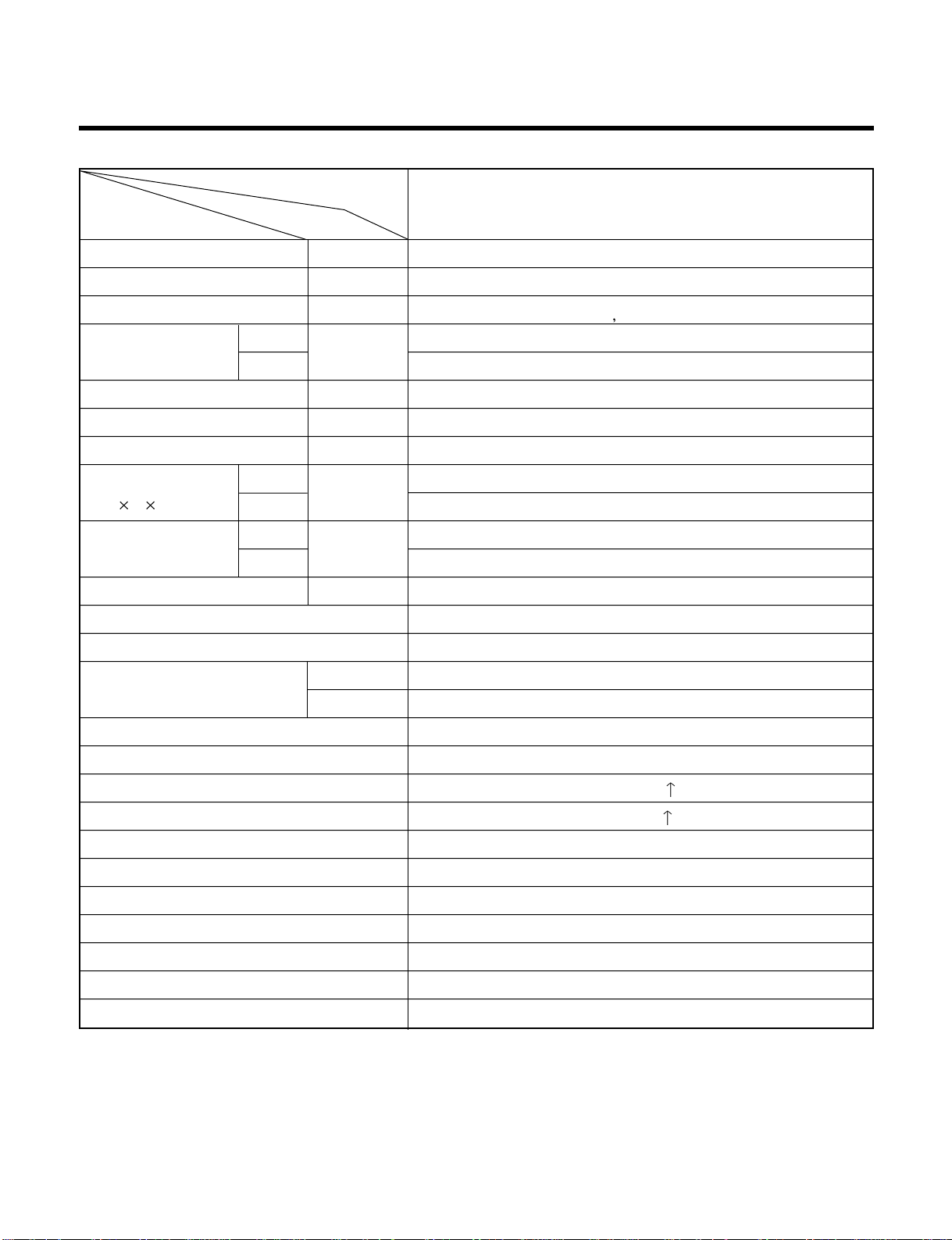
LG LV-B3620CL User manual

Contents
Functions.................................................................................................................................3
Product Specifications ...........................................................................................................5
Dimensions..............................................................................................................................6
Refrigeration Cycle Diagram..................................................................................................8
Wiring Diagram........................................................................................................................9
Operation Details ..................................................................................................................10
Display Function ...................................................................................................................15
Self-diagnosis Function........................................................................................................15
Installation .............................................................................................................................16
Operation ...............................................................................................................................33
Disassembly of the parts (Indoor Unit)...............................................................................34
2-way, 3-way Valve.................................................................................................................38
Cycle Troubleshooting Guide...............................................................................................44
Electronic Parts Troubleshooting Guide.............................................................................45
Electronic control device......................................................................................................49
Schematic Diagram...............................................................................................................50
Exploded View and Replacement Parts List.......................................................................51
–2–

Functions
• Room temperature sensor. (Thermistor)
• Maintains the room temperature in accordance with the Setting Temp.
• Indoor fan is delayed for 5 seconds at the starting.
• Restarting is inhibited for approx. 3 minutes.
• High, Med, Low, Chaos
--- Lights up in operation
--- Lights up in Sleep Mode
--- Lights up in Timer Mode
--- Lights up during compressor running
(only Cooling Model)
• Intermittent operation of fan at low speed.
• The fan is switched to low(Cooling), med(Heating) speed.
• The unit will be stopped after 1, 2, 3, 4, 5, 6, 7 hours.
• The fan is switched to intermittent or irregular operation
• The fan speed is automatically switched from high to
low speed.
• The louver can be set at the desired position or swing
up and down, right and left (not on all models) automatically.
• The setting temperature, indoor fan speed and desired
operation made are automatically set by fuzzy rule.
Indoor Unit
Operation ON/OFF by Remote controller
Sensing the Room Temperature
Room temperature control
Starting Current Control
Time Delay Safety Control
Indoor Fan Speed Control
Operation indication Lamps (LED)
Soft Dry Operation Mode
Sleep Mode Auto Control
Natural Air Control by CHAOS Logic
Airflow Direction Control
Auto Operation
–3–

–4–
Soft Dry Operation Mode.( )
Remote Controller
Operation ON/OFF
Reset
Operation Mode Selection
Fan Speed Selection
Room Temperature Display
Temperature Setting
Setting the Time or Timer
Timer Selection
Timer Setting
Timer Cancel
Sleep Operation
Airflow Direction Control
TEMPERATURE LOW HIGH
(Low) (Med) (High) (CHAOS)
Cooling Operation Mode.( ) Auto Operation Mode.( )
Fan Operation Mode
ON OFF
SET
CANCEL
: High:39°CLOW:11°C
: OFF, ON, OFF ON
: Cancel Sleep Mode, Timer ON or Timer OFF.
: 1, 2, 3, 4, 5, 6, 7hr, Off Timer
: Fan Operates without cooling.
Cooling Down to 18°C
Up to 30°C

Product Specifications (Cooling Only)
Model Name
Item Unit
Cooling Capacity Btu/h(kcal/h) 36,000(9,072)
Moisture Removal l/h 5.0
Power Source
ø
, V, Hz
1ø220, 60Hz
Indoor 20
Outdoor 58
Input W 3,900
Running Current A 18
E.E.R. Btu/h-W 9.23
Indoor 1,200 x 205 x 615
Outdoor 790 x 965 x 320
Indoor 32
Outdoor 80
Refrigerant (R-22) g 3,150
Airflow Direction Control (Up & Down) O
Remocon Type L.C.D Wireless
Liquid 3/8" (9.52)
Gas 3/4" (19.05)
Sleeping Operation O
Drain Hose O
Connecting Wire 0.75mm2
Main Power Cable 3.5mm2
Time Delay Safety Function O
Air Circulation O
Soft Dry O
Fan Speed (Indoor) 3 (Hi, Med, Low)
Timer 24Hrs
Self-Diagnosis O
Auto-Restart O
Air Circulation m3/min
Dimensions
(W H D)
Net. Weight
mm
kg
LV-B3620CL
–5–
Service Valve &
Connecting Tube

Dimensions
(1) Indoor Unit
250mm
36mm
36mm 1076mm
1200mm
205mm
615mm
392mm
265mm
468mm
R
63mm
38mm
175mm
(Installation Plate)
(Rear Side)
–6–

(2) Outdoor Unit
320
790
385 72
482 4-ø12Hole
249
71
145 500 145
10 334
354
10
265
440
925
965
130
40
80
292.5
5
3
1
2
4
(Air intake vent)
(Air intake vent)
(Air intake vent)
–7–

Refrigeration Cycle Diagram
Pipe size(Diameter: ) Piping length(m) Elevation(m)
MODEL Gas Liquid Rated Max Rated Max
LV-B3620CL 3/4" 3/8" 5 20 5 10
INDOOR UNIT OUTDOOR UNIT
HEAT
EXCHANGER
(EVAPORATOR)
HEAT
EXCHANGER
(CONDENSER)
COMPRESSOR
GAS SIDE
LIQUID SIDE
CAPILLARY TUBE
–8–
For installation over rated distance, 50g of refrigerant should be added for each meter.
ex) When installed at a distance of 15m, 500g of refrigerant should be added.
(15-5) x 50g = 500g

Wiring Diagram
(1) Indoor Unit
–9–
DISPLAY PCB
ASSY.
MAIN PCB
ASSY.
TRANS-
FORMER THERMISTOR
CN-TH
CN-TRANS
CN-FAN
RY-L
OR
RD
BL
BK
MOTOR
CAPACITOR
BR YL
GN/YL
GN/YL
FUSE
T3.15A
STEP
MOTOR
RY-COMP
CN-4WAY
CN-UP/DOWN 1,2
BR
BL
WH
CN-DISP
DOOR S/W 1,2
43
RY-M
RY-H
TERMINAL
BLOCK
1
(L)
2
(N)
34
STEP
MOTOR
4123 65
3854A20039L
(OUTDOOR)
Outdoor Unit Wiring Diagram
NOTE
BL : BLUE
BK : BLACK
BR : BROWN
OR : ORANGE GN/YL : GREEN/YELLOW
52C
TMo
Co
MAGNETIC CONTACTOR
TERMINAL BLOCK
RUN CAPACITOR FOR FMo
TM
CM
CR
MAIN TERMINAL BLOCK
COMPRESSOR
RUN CAPACITOR FOR CM
F1
FMo
FUSE (250V, 5A)
OUTDOOR FAN MOTOR
P/NO : 3854A30042T
RD : RED
WH :WHITE
YL :YELLOW WIRING OF FIELD
(CONNECTING WIRE)
TM
POWER SUPPLY
BK
Cr
52C
BK
BK
L1
T1
L2
T2
B
A
WH
BK
WH
BK
WH
BL BK
RD
RC
S
CM
WH
WH
GN/YL
WH
BL
BK
2(N)
1(L)
Co
OR YL
BL
BK OR YL
BL
BK
Co
FMo1FMo2
THMO
C
H
L
GN/YL
TO INDOOR
F1
543
2
(
N
)
1
(
L
)
(2) Outdoor Unit

3. Cooling Mode Operation
•When selecting the Cooling( ) Mode Operation, the unit will operate according to the setting by the remote con-
troller and the operation diagram is as following
Intake Air temp.
COMP. ON
(SET TEMP.+0.5°C)
COMP. OFF
(SET TEMP. -0.5°C) More than More than
3 minutes 3 minutes
Selecting Selecting Selecting
fan speed fan speed fan speed
COMPRESSOR ON OFF ON OFF ON
INDOOR FAN Low Low
Operation Details
(1) The function of main control
1. Time Delay Safety Control
•3min…The compressor is ceased for 3minutes to balance the pressure in the refrigeration cycle.
(Protection of compressor)
•5sec…
Vertical air flow direction control louvers open in 5 seconds to prevent noise between louvers and wind.
•30sec…The 4-way valve is ceased for 30sec. to prevent the refrigerant-gas abnormal noise when the Heating
operation is OFF or switched to the other operation mode while compress is off.
While compressor is running, it takes 3~5 seconds to switch.
2. Airflow Direction Control
•This function is to swing the louver up and down automatically and to set it at the desired position.
•The procedure is as the following.
1st ; Press the ON/OFF Button to operate the product.
2nd ; Press the Airflow Direction Control Button to swing the louver up and down automatically.
3nd ; Repress the Airflow Direction Control Button to set the louver as the desired position.
MODE0
1
2
3
4
5
67
135°
Cooling
MODE
MODE
MODE
MODE
MODE
MODE
MODE 9
MODE
(CLOSE)
–10–

4. Sleep Mode Auto Operation
•When selecting the Cooling( ) combined with the Sleep Mode Auto Operation( ), the operation diagram is
as following.
Cooling Mode with the Sleep Mode
•The setting temperature will be raised by 1°C 30minutes later and by 2°C 1 hour later.
•The operation will be stopped after 1, 2, 3, 4, 5, 6, 7 hours.
Intake Air temp.
COMP. ON
(SET TEMP.+0.5°C)
COMP. OFF
(SET TEMP. -0.5°C) More than More than
3 minutes 3 minutes
INDOOR FAN Low Low Low Low Low
COMPRESSOR ON OFF ON OFF ON
30 minutes 30 minutes
1°C
1°C
–11–
5. Auto Operation
•The operation procedure is as following. (Cooling & Heating Model)
If initial mode is decided, that mode is continued without the room temperature changing.
For cooling operation mode over 24°C setting temperature and fan speed are same as cooling only model.
Press Start/Stop Button
Select Auto Operation Mode
Check the Room temperature
Operation mode
Indoor fan speed are automatically decided by Fuzzy rule.
Setting temperature
Intake-air
temperature
Operation Mode Heating Soft Dry Cooling
below 21°Cbelow
24°C
~Over 24°C
Over
21°C

• Auto Operation for Cooling. (Cooling only Model)
• Auto Operation for Soft Dry
The Setting temperature will be same as that of the current intake-air temperature.
- Compressor ON temperature; Setting temperature +1°C
- Compressor OFF temperature; Setting temperature -0.5°C
•1/f rhythm louver operation : In Auto operation mode, when pressing the vertical air direction control button, lou-
ver moves as following cycle.
–12–
Operation Condition Intake-air Temperature Setting temperature Fan speed Air Direction Control
Over 26°C25°C
Over 24°C~below 26°C Intake air -1°C
Over 22°C~below 24°C Intake air -0.5°C
Over 20°C~below 22°C intake air temperture
below 20°C20°C
Over 20°C~below 30°C Fuzzy control
below 20°C20°C
over 30°C30°C
When Auto Operation
initial start
When pressing room temp-
erature setting button
during Auto Operation
Controlled
by Fuzzy logic
In this mode, when
pressing the verti-
cal air diretion con-
trol.
Button, louvers
moves to 1/f
rhythm (refer to
page 17)
Intake-Air temp
Setting Temp. +0.5°C
(Compressor OFF)
Setting Temp.-0.5°C
(Compressor ON)
Indoor Fan
Compressor ON ONOFF OFF
Fuzzy Speed
MODE0
MODE1
MODE2
MODE3
MODE4
MODE5
MODE6 MODE9
(CLOSED)
End
Start

6. Natural wind by CHAOS logic
–13–
For more fresh feeling than other fan speed mode, press
the indoor fan Speed Selector and set to CHAOS mode.
In this mode, the wind blows like natural breeze by auto-
matically changing fan speed according to the CHAOS
logic.
Intake Air temp.
OUTDOOR FAN/COMP.
INDOOR FAN
: Setting fan speed : LOW
Cooling on temp.
(Setting temp.+0.5)
Setting CHAOS Natural wind
Setting temp.
Cooling off temp.
(Setting temp.-0.5)
: CHAOS Natural wind : COMP ON : COMP OFF
GRAPH of Natural wind by the CHAOS logis (During Cooling operation)
INDOOR FAN Low Fan Low Fan
Intake Air temp.
Setting temp. +1.0˚C
(Compressor ON)
Setting temp. -0.5˚C
(Compressor OFF)
Setting temp.
2min.58sec. 2min.58sec.
10min. 10min.7min. Within 7min.
CoolingCooling
OUTDOOR FAN
COMPRESSOR
Selected
Fan Selected
Fan
ON
ON
ON
ON
OFF
OFF
OFF
OFF
ON
ON
OFF
OFF
ON
ON
OFF
OFF
ON
ON
OFF
OFF
7. Soft Dry Operation
•During Soft Dry Operation, the compressor ON temperature is the setting temperature plus 1°C, the compressor OFF
temperature is the setting temperature minus 0.5°C.
•When the room temperature rises over the compressor ON temperature, the operation mode is switched to the cool-
ing mode.
•When the room temperature falls between the compressor ON temperature and OFF temperature, the operation
mode is switched to the Soft Dry Operation.
In this temperature range, 10min. Dry Operation, 7min operation OFF. During 10min Dry operation, if the room tem-
perature falls below compressor OFF temperature, Compressor OFF.
•In micom dehumidify mode, control of fan speed is as following.

9. Protection of the evaporator pipe from frosting
If the temperature of the indoor coil is below 0°C after 7 minutes from starting the compressor, the
compressor and the outdoor fan is stopped, and then after 3 minute delay of the compressor and
the temperature of the indoor coil is over 7°C, the compressor and the outdoor fan is reoperated.
Indoor fan operates at low speed (comp. OFF) or at selected speed (comp. ON)
10. Inlet grille open
Once the inlet grille is opened during operation of the unit, the unit automatically stops operation and the
lamps will be turned-off. But memorized functions are still available.
When the inlet grille is closed again, the unit become waiting state for operation. From then, the unit can be
operated by forced operation button or Start/Stop button of remote controller.
11. Test Operation
•When pressing forced operation switch about 3 seconds, the unit operates in cooling mode at high speed fan
regardless of room temperature and resets in 18 min.
•During test operation, if remote controller signal is received, the unit operates as remote controller sets.
12. Auto Restarting Operation
•When the power is restored after a sudden power failure while in appliance operation, the mode before the
power failure is kept on the memory and the appliance should be on the automatically operates in the mode
on the memory.
•Operation Mode that is kept on the memory
- State of Operation ON/OFF
- Operation Mode/Setting Temp/Selected airflow Speed
- Sleep Timer Mode/Remaining Time of Sleep Timer(unit of hour)
–14–
8. Forced operation
•If you lose wireless remote controller, you can operate the unit with forced operation switch.
•The standard conditions are as following.
•Unit operates in low fan mode for first 15 seconds, then switched to proper operation mode according to
intake Air temperature.
Cooling Model
Operation Mode Cooling
FAN Speed High
Setting Temp. 24°C
R
Forced
Operation Button Press the Forced Operation Button.
•Press the Forced Operation Button once
again to stop operation.

–15–
Note)
For normal operation after checking by test mode, you should press SW1 nine times for resetting or reconnect
the power cord.
Self-diagnosis Function
1. Protection of the evaporator pipe from frosting
If the temperature of the indoor pipe is below 0°C after 7 mins from starting the compressor, the compressor
and the outdoor fan is stopped, and then after 3 mins delay of the compressor and the temperature of the
indoor pipe is over 7°C, the compressor and the outdoor fan is reoperated.
2. Thermistor Cut Off or Short
Cut Off/Short : Blinks on and off the operation mode LED. (0.5 sec ON/3 sec OFF)
•Coolling, Soft Dry, Fan, Heating
•Timer Mode
•Sleep Mode
•Outdoor Unit Operating
Operation Indicator
Timer Indicator
Sleep Timer Indicator
Outdoor Unit Operation
1. Heating Model
Display Function

–16–
1. Selection of the best location
1) Indoor unit
• There should not be any heat source or steam near
the unit.
• There should not be any obstacles to prevent the air
circulation.
• A place where air circulation in the room will be good.
• A place where drainage can be easily obtained.
• A place where noise prevention is taken into consider-
ation.
• Do not install the unit near the door way.
• Ensure the spaces indicated by arrows from the wall,
ceiling, or other obstacles.
2) Outdoor unit
• If an awning is built over the unit to prevent direct sun-
light or rain exposure, be careful that heat radiation
from the condenser is not restricted.
• There should not be any animals or plants which
could be affected by hot air discharged.
• Ensure the spaces indicated by arrows from the wall,
ceiling, fence or other obstacles.
3) Piping length and the elevation
1. Installation of Indoor, Outdoor Unit
More than
20cm
More than eye-level
More than
20cm
R
R
More than
20cm
More than
20cm
(Ceiling installation)
(Floor/Wall installation)
Indoor unit
Outdoor unit
B
A
More than 10cm More than 10cm
More than 70cm
MODEL
36K BTU
3/4" 3/8" 5 20 5 10 50
GAS LIQUID
Elevation B(m)
Length A(m) * Additional
refrigerant
(g/m)
Pipe Size
Rated Rated
Max. Max.
•If this Model is installed at a distance of 15m, 500g of refrigerant should
be added............................................................(15-5) x 50g = 500g
Installation

–17–
2. Indoor unit installation
■Before Installing, prepare Installation Plates
•'Installation Plates' are attached at the bottom of
indoor unit.
Detach them by removing each 3 screws at both
sides.
•Detach 'Side Plate (R,L)' by removing each 2 screws
on both sides.
•Pull the upper right and left side of 'Inlet Grille' to the
front, and it will stop at slightly tilted position.
•Unhook the 'Inlet hanger' from the 'Hanger screw' on
the both left and right side.
•Detach the 'Inlet Grille' from the Indoor Unit.
1) Installation on the ceiling
•Measure and mark the position for the Suspen-
sion bolts and the piping hole.
•Drill the hole for anchor nut on the ceiling.
Before secure the Installation Plates, select the bent
direction of the Installion Plate to the inside or the
outside according to the installation circumstances.
•Drill the piping hole on the wall slightly tilted to the
outdoor side using a ø70 hole-core drill.
R
1076
Suspension
bolt Center-line for the
piping hole
265
1236 265
Install Plate
1)
2)
R
5~7mm
Indoor Outdoor
WALL
Side Plate
Inlet Grille
Inlet hanger
Hanger
screw

–18–
•Insert the nuts and washer onto the suspension bolts
for locking the suspension bolts on the ceiling.
•Mount the suspension bolts to the anchor-nuts firmly.
•Secure the Installation plates onto the Suspension
bolts (adjust level roughly.) using nuts, washers and
spring washers.
•Engage 2 hooks on the both left and right side
of the unit to the lower slot of Installation Plates.
•Adjust a level with a level gauge on the direction
of left-right, back-forth by adjusting suspension
bolts.
•Move the hooks on the unit to the upper slot of
Installation Plates. Then the unit will be declined
to the bottomside so as to drain well.
Washer
Nut
Suspension
bolts
Ceiling
Anchor nut
Suspension
bolts
Spring
washer
max.
12mm Washer
Nut
1)
2)
Suspension
bolt
Installation plate
Adjust a level
R
Level gauge
Lower slot
R
R
Upper slot

–19–
Drain hose
Ceiling
Ceiling
Ceiling
Front of view
Side of view
1. Install declination of the indoor unit is very important for the drain of the convertible type air
conditioner.
2. Minimum thickness of the insulation for the connecting pipe shall be 7mm.
3. If the Installation Plates are fixed to horizontal line, the indoor unit after installing will be declined
to the bottomside.
CAUTION
•The unit must be horizontal or declined to the drain hose connected when finished installation.
•The unit must be declined to the bottomside of the unit when finished installation.

–20–
R
R
R
1
2
•
Before working, refer to "Connecting pipe
and cable to Indoor Unit" on page 26.
R
Inlet hanger
Hook
Cabinet Bottom
•Secure the unit to the Installation Plates with four M8
bolts and washers.
•Hook up the Inlet Grille Hook to the cabinet.
•Hang the Inlet Hanger to the screw.
•Fit the projection hooks of the side plates to the 'Side
Panel' and the 'Front Panel' by lifting it.
•Fasten the screws.
Table of contents
Other LG Air Conditioner manuals