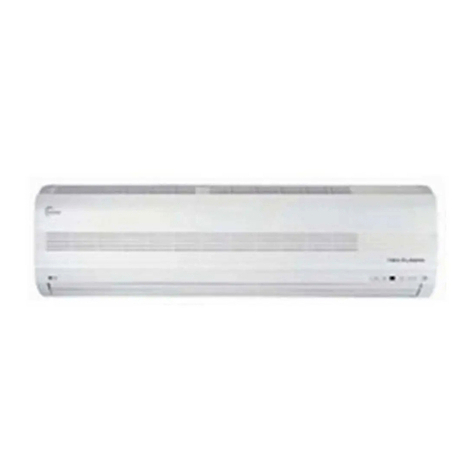
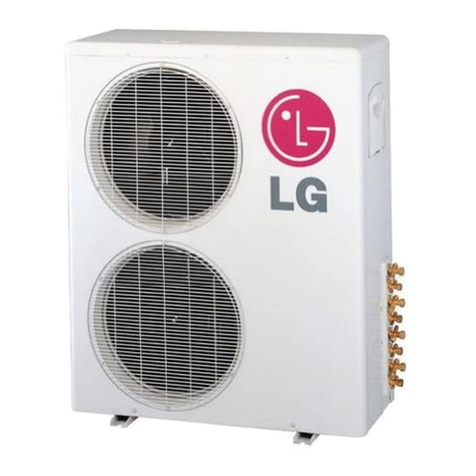
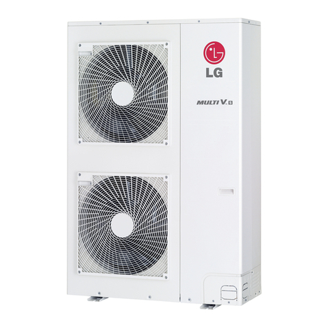
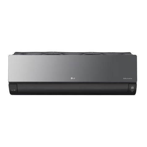
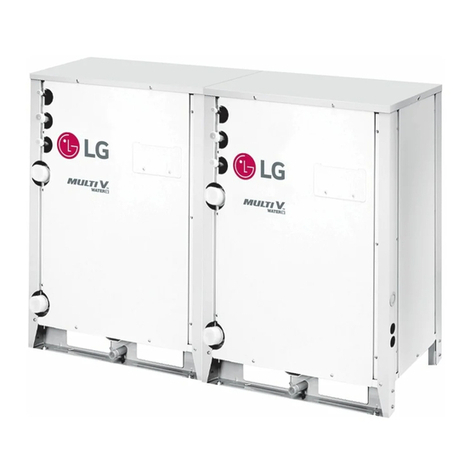
LG LVNH246BLA1 User manual

ENGLISH
êÛÒÒÍËÈ
LG
Air Conditioner
INSTALLATION MANUAL
LG
IMPORTANT
• Please read this instruction manual completely
before installing the product.
• Installation work must be performed in
accordance with the national wiring standards
by authorized personnel only.
• Please retain this installation manual for future
reference after reading it thoroughly.
Type : Convertible

2Convertible Air Conditioner
Convertible Air Conditioner Installation Manual
TABLE OF CONTENTS
Safety Precautions .....3
Installation of Indoor,
Outdoor unit................5
Connecting Pipes to the
Indoor Unit ................14
Connecting Pipes to the
Outdoor Unit .............22
Checking the Drainage
....................................22
Connecting Cables
between Indoor Unit and
Outdoor Unit .............24
Air Purging of the
Connecting Pipes and the
Indoor Unit ...............27
Test running..............29
Installation guide
at the seaside............30
•
Installation Plate
•
Four Type “A” screws
•
Connecting cable
•
Pipes: Gas side
Liquid side
•
Insulated drain hose
•
Insulation materials
•
Additional Drain hose
(Inner Dia...............25mm)
• Two type “B” screws
•
Level
•
Screw driver
•
Electric drill
•
Hole core drill (ø70mm)
•
Flaring Tools set
•
Specified Torque Wrenches
•
Specified Torque Wrenches
•
Screw driver
•
Hexagonal Wrench
(4mm/5mm)
•
Gas-leak Detector
•
Owner’s Manual
•
Thermometer
Installation
Requirements Required Parts Required Tools

ENGLISH
Safety Precautions
Installation Manual 3
Safety Precautions
To prevent injury to the user or other people and property damage, the following instructions
must be followed.
■Incorrect operation due to ignoring instruction will cause harm or damage. The seriousness is
classified by the following indications.
■Meanings of symbols used in this manual are as shown below.
WARNING
CAUTION
This symbol indicates the possibility of death or serious injury.
This symbol indicates the possibility of injury or damage.
Be sure not to do.
Be sure to follow the instruction.
WARNING
■Installation
Do not use a defective or
underrated circuit breaker.
Use this appliance on a
dedicated circuit.
• There is risk of fire or electric shock.
For electrical work, contact
the dealer, seller, a qualified
electrician, or an Authorized
Service Center.
•
Do not disassemble or repair the product.
There is risk of fire or electric shock.
Always ground the product.
•
There is risk of fire or electric shock.
Install the panel and the cover
of control box securely.
• There is risk of fire or electric shock.
Always install a dedicated
circuit and breaker.
• Improper wiring or installation may
cause fire or electric shock
Use the correctly rated
breaker or fuse.
• There is risk of fire or electric shock.
Do not modify or extend the power cable.
• There is risk of fire or electric shock.
Be cautious when unpacking and installing the
product.
• Sharp edges could cause injury. Be especially careful of
the case edges and the fins on the condenser and
evaporator.
For installation, always contact the dealer or an
Authorized Service Center.
• There is risk of fire, electric shock, explosion, or injury.
Do not install the product on a defective
installation stand.
• It may cause injury, accident, or damage to the product.

Safety Precautions
4Convertible Air Conditioner
■Operation
Be sure the installation area does not
deteriorate with age.
•
If the base collapses, the air conditioner could fall with it,
causing property damage, product failure, and personal injury.
Do not let the air conditioner run for a long time
when the humidity is very high and a door or a
window is left open.
• Moisture may condense and wet or damage furniture.
Do not store or use flammable gas or
combustibles near the product.
• There is risk of fire or failure of product.
■Installation
CAUTION
Always check for gas (refrigerant) leakage after
installation or repair of product.
• Low refrigerant levels may cause failure of product.
Install the drain hose to ensure that water is
drained away properly.
• A bad connection may cause water leakage.
Keep level even when installing the product.
• To avoid vibration or water leakage.
Do not install the product where the noise or
hot air from the outdoor unit could damage the
neighborhoods.
• It may cause a problem for your neighbors.
Use two or more people to lift and transport the
product.
• Avoid personal injury.
Do not install the product where it will be
exposed to sea wind (salt spray) directly.
• It may cause corrosion on the product. Corrosion,
particularly on the condenser and evaporator fins, could
cause product malfunction or inefficient operation.

ENGLISH
Installation Manual 5
Installation of Indoor, Outdoor Unit
1. Selection of the best location
1) Indoor unit
• There should not be any heat source or steam
near the unit.
• There should not be any obstacles to prevent
the air circulation.
• A place where air circulation in the room will be
good.
• A place where drainage can be easily obtained.
• A place where noise prevention is taken into
consideration.
• Do not install the unit near the door way.
• Ensure the spaces indicated by arrows from the
wall, ceiling, or other obstacles.
2) Outdoor unit
• If an awning is built over the unit to prevent
direct sunlight or rain exposure, make sure that
heat flow from the condenser is not restricted.
• Ensure that the space around the back and
sides is more than 300mm. The front of the unit
should have more than 700mm of space.
• Do not place animals and plants in the path of
the warm air.
• Take the weight of the air conditioner into
account and select a place where noise and
vibration are minimum.
• Select a place where the warm air and noise
from the air conditioner do not disturb neighbors.
More than
200mm
More than
1200mm
More than
200mm
R
R
More than
200mm
More than
200mm
(Ceiling installation)
(Floor/Wall installation)
More than
300mm
More than 300mm
More
than 600mm
More than 600mm
More than
700mm
More than
700mm
More than
300mm
More than
700mm
VB CHASSIS
VK,VJ,VL CHASSIS

6Convertible Air Conditioner
Installation of Indoor, Outdoor Unit
3) Piping length and the elevation
Outdoor unit
Indoor unit
A
B
Outdoor unit
Indoor unit
A
B
A
Oil trap
Outdoor unit
Indoor unit
B
•Rated performance for refrigerant line length of:7.5m
•Capacity is based on standard length and maximum allowance length is on the basis of
reliability.
•Improper refrigerant charge may result in abnormal cycle.
•Oil trap should be installed every 10 meters.
CAUTION
Model
LV-C286BLA1 5/8"(15.88mm) 1/4"(6.35mm) 7.5 30 5 20 25
LV-H246BLA1 5/8"(15.88mm) 1/4"(6.35mm) 7.5 30 5 20 40
LV-C362KLA0 5/8"(15.88mm) 1/4"(6.35mm) 5 20 5 30 25
LV-C602LLA0 3/4"(19.05mm) 3/8"(9.52mm) 7.5 20 5 30 60
LV-C60BLLA0 3/4"(19.05mm) 3/8"(9.52mm) 7.5 20 5 30 50
LV-C602LLA2 3/4"(19.05mm) 3/8"(9.52mm) 7.5 20 5 30 50
*Additional
refrigerant(g/
m)
Pipe Size
(Diameter:Ø) Length A(m) Elevation B(m)
Standard Max. Standard Max.
Gas Liquid

ENGLISH
Installation Manual 7
Installation of Indoor, Outdoor Unit
1076
Suspension
bolt Center-line for the
piping hole
(Unit : mm)
265
1236 265
Install Plate
1)
2)
5~7mm
Indoor Outdoor
WALL
Side Plate
Inlet Grille
Inlet hanger
Hanger
screw
R
1. Indoor unit installation
■
Before Installing, prepare Installation
Plates
• 'Installation Plates' are attached at the bottom of
indoor unit.
Detach them by removing each 3 screws at both
sides.
• Pull the upper right and left side of 'Inlet Grille' to
the front, and it will stop at slightly tilted position.
• Unhook the 'Inlet hanger' from the 'Hanger screw'
on the both left and right side.
• Detach the 'Inlet Grille' from the Indoor Unit.
• Detach 'Side Plate (R,L)' by removing each 3
screws on both sides.
1) Installation on the ceiling
• Measure and mark the position for the Suspension
bolts and the piping hole.
• Drill the hole for anchor nut on the ceiling.
Before secure the Installation Plates, select
the bent direction of the Installion Plate to the
inside or the outside according to the
installation circumstances.
• Drill the piping hole on the wall slightly tilted to the
outdoor side using a ø70 hole-core drill.
■VB CHASSIS

8Convertible Air Conditioner
Installation of Indoor, Outdoor Unit
Washer
Nut
Suspension
bolts
Ceiling
Anchor nut
Suspension
bolts
Spring
washer
Max.
12mm Washer
Nut
1)
2)
Suspension
bolt
Installation plate
Adjust a level
R
Level gauge
Lower slot
R
R
Upper slot
• Insert the nuts and washer onto the suspension
bolts for locking the suspension bolts on the
ceiling.
• Mount the suspension bolts to the anchor-nuts
firmly.
• Secure the Installation plates onto the Suspension
bolts (adjust level roughly.) using nuts, washers
and spring washers.
• Engage 2 hooks on the both left and right side of
the unit to the lower slot of Installation Plates.
• Adjust a level with a level gauge on the direction of
left-right, back-forth by adjusting suspension bolts.
• Move the hooks on the unit to the upper slot of
Installation Plates. Then the unit will be declined to
the bottomside so as to drain well.

ENGLISH
Installation Manual 9
Installation of Indoor, Outdoor Unit
Drain hose
Ceiling
Ceiling
CAUTION
Ceiling
1. Install declination of the indoor unit is very important for the drain of the
convertible type air conditioner.
2. Minimum thickness of the insulation for the connecting pipe shall be 7mm.
3. If the Installation Plates are fixed to horizontal line, the indoor unit after installing
will be declined to the bottomside.
Front of view
• The unit must be horizontal or declined to the drain hose connected when finished
installation.
• The unit must be declined to the bottomside of the unit when finished installation.
Side of view

10 Convertible Air Conditioner
Installation of Indoor, Outdoor Unit
•
Before working, refer to "Connecting pipe
to Indoor Unit" on page 16.
R
R
Hook
Cabinet Bottom
R
R
Inlet hanger
• Secure the unit to the Installation Plates with
four M8 bolts and washers.
• Fit the projection hooks of the side plates to the
'Side Panel' and the 'Front Panel' by
lifting it.
• Fasten the screws.
• Hook up the Inlet Grille Hook to the cabinet.
• Hang the Inlet Hanger to the screw.

ENGLISH
Installation Manual 11
Installation of Indoor, Outdoor Unit
1076
more than
260
265
Washer
Nut
Wall
Anchor nut
Spring
washer
Wall
5~7mm
Less than
12mm
1236
Indoor Outdoor
(Unit : mm)
(Unit : mm)
2. Installation on the Wall
• Select and mark the position for fixing bolts and
piping hole.
Decide the position for fixing bolts slightly tilted to
the drain direction after considering the direction of
drain hose.
• Drill the hole for anchor nut on the wall.
• Drill the piping hole on the wall slightly tilted to the
outdoor side using a ø70 hole-core drill.
• Secure the 'Install Plate' onto the wall with four
anchor bolts, washers and spring washers.
Before secure the Install Plates, select the bent
direction of the 'Install Plate' to the inside or
outside according to the installation circumstances.

12 Convertible Air Conditioner
Installation of Indoor, Outdoor Unit
•
Before working, refer to "Connecting the
pipes to the Indoor Unit" on page 16.
R
Inner slot
Install the Indoor unit onto Installation Plate.
• Insert 2 hooks on the both left and right side of the
unit to the inner slot (wall side) of the Installation
Plate.
• Secure the unit to the Installation Plate with four M8
bolts and washers.
• Fit the projection hooks of the side plates to the
'Side Panel' and the 'Front Panel' by
lifting it.
• Fasten the screws.
• Hook up the Inlet Grille Hook to the cabinet.
• Hang the Inlet Hanger to the screw.

ENGLISH
Installation Manual 13
Installation of Indoor, Outdoor Unit
Floor mount
bracket
Slot
Floor mount
bracket
Install plate
Slot
Piping hole
Wall
5~7mm
Indoor Outdoor
more than 760mm
From the left wall
From the
right wall
more than 840mm
Wall
448mm
3. Installation on the floor
Installation of Mount Bracket.
• Select and mark the position for Mount Brackets
and the piping hole.
• Drill the hole for the anchor nut on the wall.
• Drill the piping hole using a ø70 hole-core drill.
• Secure the Mount Brackets on the wall with four M4
screws.
Install the indoor unit onto the Mount Brackets.
• Engage the slot at the back of the unit with Mount
Bracket.
• Drill the piping hole with 70mm dia, hole core drill.
• Piping hole should be slightly slant to the outdoor
side.
After Installing, reassemble detached
parts.
• Hang the 'Inlet Grille' and hook the 'Inlet Hanger' to
the Hanger Screw.
• Assemble the 'Side Plates(R,L)' with 2 screws on
both left and right side.

14 Convertible Air Conditioner
Installation of Indoor, Outdoor Unit
1.Preparing Work for
Installation
Open side cover
1. Remove two screws from side-cover as shown in fig.
2. Unlock side-cover from side panel by slightly pulling
the edge of side cover.
3. Tap the side-cover with your palm on the
backside.(Inlet grill side.)
4. Hold the side-cover with other hand while tapping to
prevent it to fall down.
5. The Drain hole is on the left side of the unit and side
cover opening is common for drain pipe,connecting
pipe and wiring diagram.
6. Remove the rubber stopple in the desired drain
direction.
7. Knock out the pipe hole from the left side-cover with
the help or nipper/plier.
8. Knock hole on right side-cover only if right side is
selected for water drain.
2
1
Edge part
■VK,VL,VJ CHASSIS

ENGLISH
Installation Manual 15
Installation of Indoor, Outdoor Unit
MOUNTING THE ANCHOR NUT AND
BOLT
• Prepare 4 suspension bolts. (Each bolts length
should be same.)
• Measure and mark the position for the Suspension
bolts and the piping hole.
• Drill the hole for anchor nut on the ceiling.
• Insert the nuts and washer onto the suspension bolts
for locking the suspension bolts on the ceiling.
• Mount the suspension bolts to the anchor-nuts firmly.
• Secure the hangers onto the Suspension bolts
(adjust level roughly.) using nuts, washers and
spring washers.
• Adjust a level with a level gauge on the direction of
left-right, back-forth by adjusting suspension bolts.
• Adjust a level on the direction of top-bottom by
adjusting supension bolts. Then the unit will be
declined to the bottomside so as to drain well.
Suspension bolt
B
A
Washer
Nut
Suspension
bolts
Ceiling
Anchor nut
Suspension
bolts
Spring
washer
Max.
12mm Washer
Nut
Flat washer for M10
(accessory)
Flat washer for M10
(accessory)
Hanging bolt
(W3/8 or M10)
Nut
(W3/8 or M10)
Nut
(W3/8 or M10)
Spring washer
(M10)
: Tighten the nut and bolt to prevent
unit falling.
CAUTION
VL 1655 320
VK 1255 320
VJ 855 320
DIM.
MODEL
AB
DRILL A HOLE IN THE WALL.
• Drill the piping hole with a ø70mm hole core drill. Drill
the piping hole at either the right or the left with the
hole slightly slanted to the outdoor side.
5-7mm
Indoor
WALL
Outdoor

16 Convertible Air Conditioner
Installation of Indoor, Outdoor Unit
Hang the Indoor unit on suspension bolt as per following guidelines:
1. Lift the indoor unit to sufficient height.
2. Insert the suspended part of four suspension bolt in the four hangers provided on the side of main body one by
one.
3. Lower the indoor unit till the hangers rest on their respective flat washer.
4. Adjust the level in the top down direction by adjusting the suspension bolts.
Inclined the indoor unit as per direction provided in the fig
Ceiling
Ceiling
10~20mm
5~10mm
1. Install declination of the indoor unit is very important for the drain of the convertible type
air conditioner.
2. Minimum thickness of the insulation for the connecting pipe shall be 10mm.
3. If the Installation Plates are fixed to horizontal line, the indoor unit after installing will be
declined to the bottomside.
Front of view
• The unit must be horizontal or inclined at angle.
• The inclination should be less than or equal to 1° or in between 10 to 20mm inclined in drain direction as
shown in fig.
• The unit must be declined to the bottomside of the unit when finished installation.
Side of view
: Installation Information For Declination
CAUTION
2. Indoor unit installation

ENGLISH
Installation Manual 17
Connecting Pipes to the Indoor Unit
Copper
tube
90°Slanted Uneven Rough
Pipe
Reamer
Point down
Flare nut
Copper tube
Bar
Copper pipe
Clamp handle Red arrow mark
Cone
Yoke
Handle
Bar
"A"
Inclined
Inside is shining without scratches
Smooth all round
Even length
all round
Surface
damaged
Cracked Uneven
thickness
= Improper flaring =
1. Preparation of Piping
Main cause of gas leakage is defect in flaring
work. Carry out correct flaring work in the
following procedure.
1) Cut the pipes and the cable.
■Use the accessory piping kit or the pipes
purchased locally.
■Measure the distance between the indoor and
the outdoor unit.
■Cut the pipes a little longer than measured
distance.
■Cut the cable 1.5m longer than the pipe
length.
2) Burrs removal
■Completely remove all burrs from the cut cross
section of pipe/tube.
■Put the end of the copper tube/pipe to
downward direction as you remove burrs in
order to avoid to let burrs drop in the tubing.
3) Putting nut on
■Remove flare nuts attached to indoor and
outdoor units, than put them on pipe/tube
having completed burr removal.
(Not possibe to put them on after flaring work)
4) Flaring work
■Carry out flaring work using dedicated flaring
tool for R-410A as shown right.
Firmly hold copper pipe in a die in the dimension
shown in the table above.
5) Check
■Compare the flared work with figure below.
■If flare is noted to be defective, cut off the
flared section and do flaring work again.
Outside diameter A
mm inch mm
Ø6.35 1/4 1.1~1.3
Ø9.52 3/8 1.5~1.7
Ø12.7 1/2 1.6~1.8
Ø15.88 5/8 1.6~1.8
Ø19.05 3/4 1.9~2.1

18 Convertible Air Conditioner
Connecting Pipes to the Indoor Unit
2. Connecting of Piping - Indoor
1. Prepare the indoor unit piping and drain hose for
installation thought the wall.
2. Align the center of the liquid side pipe.
3. Sufficiently tight the flare nut of the liquid side pipe
with hands.
4. Tight the flare nut with two spanner, as shown.
5. Align the center of gas side pipes.
6. Sufficiently tight the flare nut of the gas side pipe with
hands.
7. Tight the flare nut with two spanner as shown.
8. If drain pipe need to be extended at the indoor side
attach the drain pipe with indoor unit drain hose as
shown in fig.
Wrap the insulation material around
connection portion
9. Overlap the connection connecting pipe insulation
material and the indoor pipe insulation martial. Bind
them together with the vinyl tape. So that here may
not be any gap.
mm inch kgf.cm
Ø6.35 1/4 180~250
Ø9.52 3/8 340~420
Ø12.7 1/2 550~660
Ø15.88 5/8 630~820
Ø19.05 3/4 990~1,210
Outside diameter Torque
Indoor unit tubing Flare nut Pipes
Wrench
Indoor unit tubing
Open-end wrench (fixed)
Connection pipe
Flare nut
Vinyl tape(narrow)
Adhesive
Drain pipe
Indoor unit drain hose
Plastic bands Insulation material

ENGLISH
Installation Manual 19
10. If the piping and the drain hose are in common
direction bundle the piping and the drain hose
together by wrapping them with vinyl tape.
11. Rout the indoor tubing and the drain hose to the
required piping hole.
12. Insulation Thickeness
Common direction of drain and piping.
Tape
the tubing, drain hose and the connecting cable.
Be sure that the drain hose is located at the
lowest side of the bundle. Locating at the upper
side can cause drain pan to overflow inside the
unit.
If the drain hose is routed inside the room,
insulate the hose with an insulation material* so
that dripping from "sweating"(condensation) will
not damage furniture or floors.
*Foamed polyethylene or equivalent is
recommended.
NOTICE
NOTICE
Connecting Pipes to the Indoor Unit
Wrap with vinyl tape
Drain hose
Pipe
Vinyl tape(wide)
Connecting
cable
Gas side
piping
Liquid side
piping
Drain hose
Vinyl tape(narrow)
Connection pipe
Connecting cable
Vinyl tape (wide) Wrap with vinyl tape
Indoor unit pipe
Pipe
Ø6.35 More than 9t More than 9t
Liquid Ø9.52
Ø12.7 More than 13t More than 13t
Ø9.52
Gas Ø12.7
More than More than More than More than
Ø15.88
13t 19t 19t 25t
Ø19.05
Classification
Area with cooling
Normal Particular
Area with cooling
Normal
Particular

20 Convertible Air Conditioner
Connecting Pipes to the Indoor Unit
R
R
R
Drain Hose
BOTTOM
Drain Hose
Hose Hanger
Piping
Hose
Bracket
1
3
4
5
2
Hose Hanger
Hose
Hanger
3. Installation on the ceiling
1) Connecting the pipes to the indoor unit
The pipe can be connected to right side, bottom or
back of the unit.
1. For the Right Side Piping
• After bending an end of the connecting tube, align
the center of the pipings and sufficiently tighten the
flare nut with fingers.
• Finally, tighten the flare nut with torque wrench until
the wrench clicks.
• Connect the Drain Hose insulated to the drain
outlet. Drain hose should be go through under the
Hose Bracket as shown in figure .
• Hang the drain hose on the hose hanger and fix it
to the hole of the hose bracket with a screw.
2. For the Bottom Side Piping
• Remove the knock-out on the bottomside of Inlet
Grille
• Align the center of the pipings and sufficiently
tighten the flare nut with fingers.
• Finally, tighten the flare nut with torque wrench until
the wrench clicks.
• Connect the Drain Hose insulated to the drain
outlet.
• Hang the drain hose on the hose hanger and fix it
to the hole of cabinet bottom with a screw.
2) Connecting the Drain Hose
• The drain hose can be connected to not only the
right side but also left side of the unit.
• If the drain hose is connected to the left side, it
should go through the cabinet bottom.
• Hang the drain hose on the hose hanger and fix it
to the hole of cabinet bottom with a screw.
This manual suits for next models
1
Table of contents
Other LG Air Conditioner manuals
Popular Air Conditioner manuals by other brands

DURASTAR
DURASTAR DRAL12F1A installation manual

Beper
Beper Mammut VE550 use instructions

Carrier
Carrier 50ZP Series owner's manual

Beko
Beko 10M-8899243200-4921-01 user manual

Innova
Innova 2.0 Instructions for installation, use and maintenance manual

Carrier
Carrier 50MH Installation, Start-Up and Service Instructions