
-8-
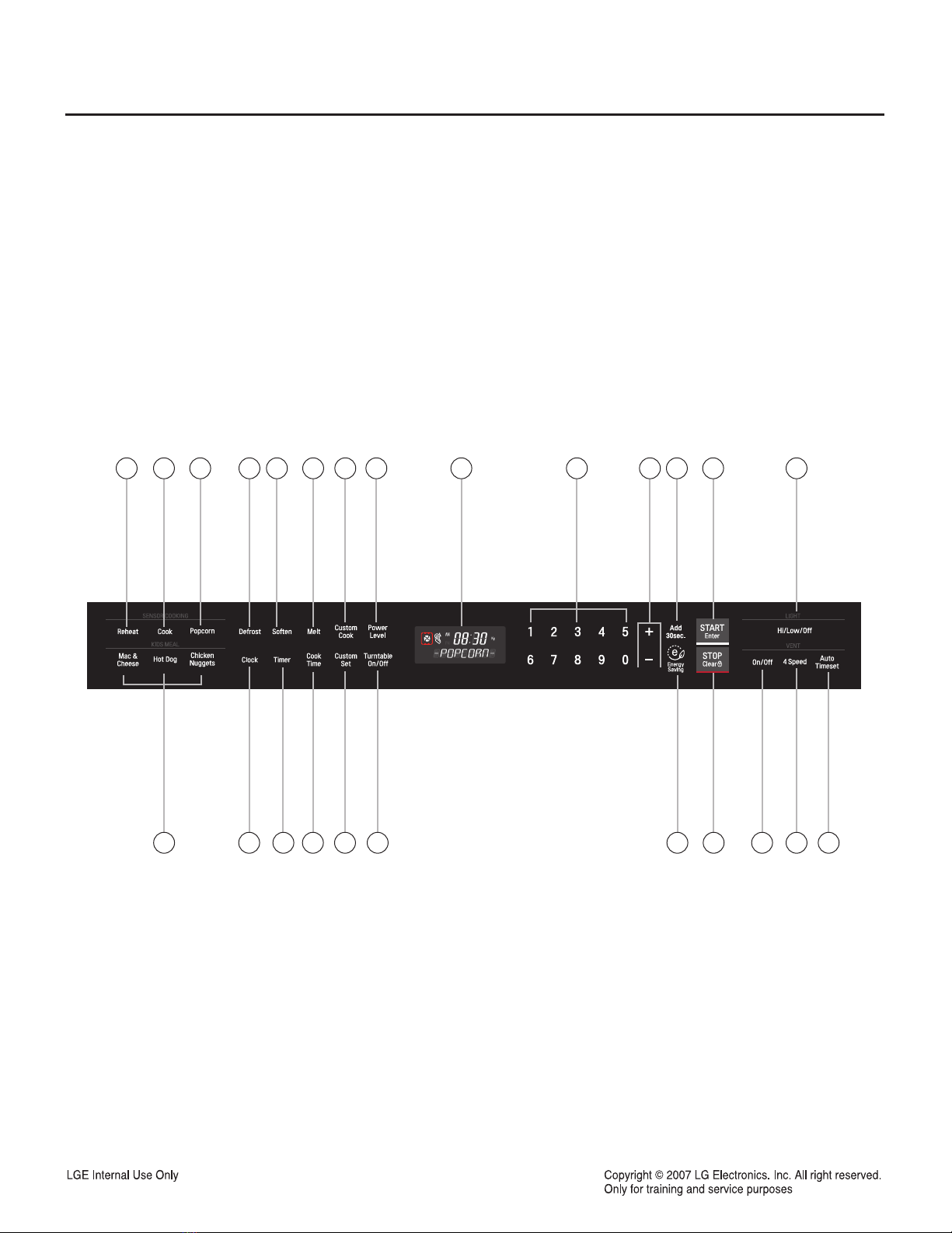
4-2. Explanation of Control Panel
1. AUTO REHEAT Press this button to reheat dinner
plate, soup/sauce, casserole, roll/muffin.
2. AUTO COOK Press this button to cook fresh
vegetables, frozen vegetables, rice, or casseroles.
3. POPCORN Press this button when popping
popcorn in your microwave oven.
4. DEFROST Touch this button to defrost frozen
food.
5. SOFTEN Press this button to soften butter, ice
cream, cream cheese, or frozen juice.
6. MELT Press this button to melt butter or
margarine, chocolate, cheese, or marshmallows.
7. CUSTOM COOK Touch this button to make oven
remember Cook time and Power level.
8. POWER LEVEL Press this button to select a
cooking power level.
9. DISPLAY The Display includes a clock and
indicators to tell you the time of day, cooking time
settings and cooking functions selected.
10. NUMBER Press this button to enter cooking
time, power level, quantities or weights.
11. +, - Touch this button to add or subtract ten
seconds of cooking time each time you touch it.
12. ADD 30 SEC Press this button to control the add
30sec. cook time.
13. START/ENTER Press this button to start a
function. If you open the door after oven begins
to cook, press START/ENTER again.
14. LIGHT HIGH/LOW/OFF touch this button to turn
the cooktop/coutertop light on high/low or off.
15. KIDS MEAL Select type of dish to reheat HOT
DOG, MAC & CHEESE or CHICKEN
NUGGETS.
16. CLOCK Press this button to enter the time of
day.
17. TIMER
18. COOK TIME Press this button to set a cooking
time.
19. CUSTOM SET Touch this pad to change the
oven's default setting for sound, clock, disply
speed, and defrost weight.
20. TURNTABLE ON/OFF
21. ENERGY SAVING Press this button to save
energy.
22. STOP/CLEAR Press this button to stop the oven
or clear all entries.
23. VENT ON/OFF touch button to turn the vent on
slow or off.
24. VENT 4 SPEED Touch button to change vent
speed.
25. VENT AUTO TIMESET Touch this button to set
ventilation time. (1, 3, 5, 10, and 30 minutes.)


M Service manual")


