
-8-
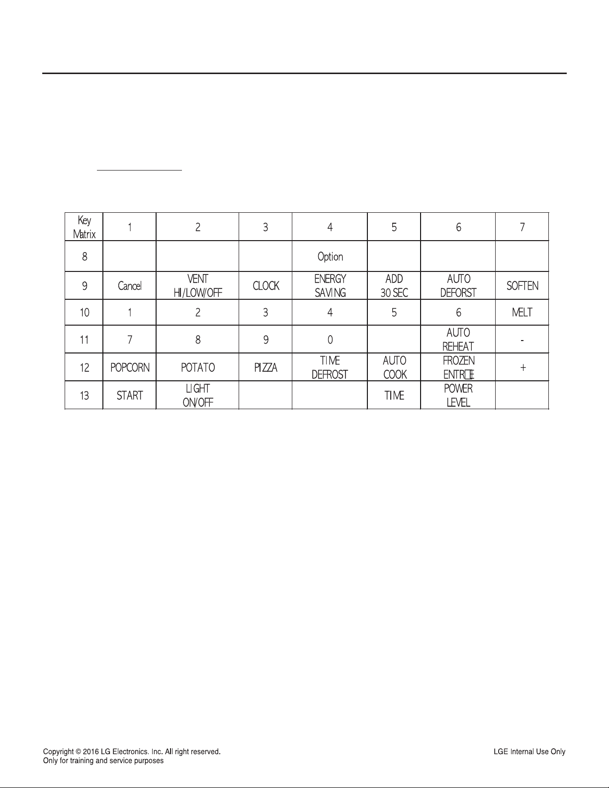
4-2. Explanation of Control Panel
1. DISPLAY. The Display includes a clock and
indicators to tell you time of day, cooking time
settings and cooking functions selected.
2. Popcorn. Touch this pad when popping popcorn
in your microwave oven.
3. Potato. Touch this pad to cook up to 4 potatoes
without entering a cook time or power.
4. Frozen Entree. uch this pad to cook a 10 to 20
ounce (284 to 567 g) frozen entree without
entering a cook time or power.
5. Auto Cook. Tuch this pad to cook microwavable
foods without entering a cook time or power.
6. Soften. Touch this pad to soften butter, icecream,
cream cheese,frozen juice.
7. Melt. Touch this pad to melt butter or
margarine, chocolate,cheese,marshmallow.
8. Time. Touch this pad followed by number pads to
set a cooking time.
9. NUMBER- Touch number pads to enter cooking
time, power level, quantities or weights.
10. Less. Touch this pad to subtract ten seconds of
cooking time each time you press it.
11. Light On/Off. Touch this pad to turn the cooktop/
countertop light on or off.
12. Pizza. Touch this pad to reheat one or several
slices of pizza without entering a cook time or
power.
13. Auto Reheat. Touch this pad to reheat
microwavable foods without entering a cook time
or power.
14. Time Defrost. Touch this pad to set a defrost
time.
15. Auto Defrost. Touch this pad followed by
number pads to thaw frozen meat by weight.
16. Power Level. Touch this pad to select a cooking
power level.
17. Clock. Touch this pad to enter the time of day.
18. START Enter. Touch this pad to start a function.
If you open the door after oven begins to cook,
retouch START Enter.
19. STOP Clear. Touch this pad to stop the oven or
clear all entries.
20. Energy Saving. Touch this pad to save energy.
21. More. Touch this pad to add ten seconds of
cooking time each time you press it.
22. Add 30 Sec. Touch this pad to add 30 seconds
of cooking time each time you press it.
23. Vent Hi/Low/Off. Touch this pad to turn the Vent
on or off.
NOTE: If you try to enter incorrect instructions,
you will not hear any tones. Touch STOP Clear and
re-enter the instructions.


M Service manual")


