LG MB-390A User manual

MICROWAVE OVEN
SERVICE MANUAL
MODEL : MB-390A
CAUTION
BEFORE SERVICING THE UNIT, READ THE
SAFETY PRECAUTIONS IN THIS MANUAL.

This microwave oven is designed for household use only.
It is not recommended for commercial purposes.
DESCRIPTION
MB-390A
230 Volts AC 50 Hz
Single phase, 3 wire grounded
Microwave 1,200W
Grill 1,100W
800 Watts full microwave power (IEC705)
2,450 MHz
2M214 - 39F, 2M218J, 2M254J
60 Min.
483 (W) x 285 (H) x 360 (D) mm
312 (W) x 198 (H) x 316 (D) mm
13.7 kg (approx.)
15.1 kg (approx.)
Microwave Power for Variable Cooking
Power level
Max
600W
360W
Defrost
90W
Grill
Owner's manual
Glass tray
Rotating ring
Grill rack
1-1
ITEM
MODEL
Power Requirement
Power Output
Microwave Frequency
Magnetron
Timer
Outside Dimensions
Cavity Dimensions
Net Weight
Shipping weight
Control Complement
Name Plate Location
Accessories
SPECIFICATIONS
Back side

4-1
OPERATING INSTRUCTIONS
FEATURES
CONTROL PANEL
Oven Front Plate
Window Door Screen
Door Seal
Display Window
Control Panel
Safety Door Lock System
Turntable
Rotating Ring
Grill Rack
90
Defrost
360
600
Max
012
3
4
6
7
8
9
20
40
50
60
30
10
5
0.1
0.2
0.3
0.4
0.5
Mins/kg
Watt
Min
1
2
1. POWER CONTROL KNOB: Used in selected the desired power level for cooking.
2. TIMER KNOB: Used to set the cooking time.
3. DOOR OPEN BUTTON: Press to open the door.

4-2
OPERATING SEQUENCE
MICROWAVE COOKING
1. Open the oven door, place the food on the
turntable in the oven, and close the oven door.
2. Set the function selector to the microwave.
3. Set the microwave power selector to the desired
power level. There are five power levels from
WARM to HIGH. The power selector can be set to
any one of these positions.
NOTE:
•Each number represents minutes. To ensure
accurate timing, it is advisable to turn the timer knob
slightly passed the desired cooking time and then
back to the proposed setting.
•Press the door opener to check the cooking
condition during oven operation. Opening the door
during oven operation automatically turns off the
oven and stops the timer. If cooking is to continue,
close the door. Cooking will be resumed until the full
cooking time has elapsed.
GRILL COOKING
1. Open the oven door, place the food on the rack in
the oven, and close the oven door.
2. Set the function.
3. Set the timer to the desired cooking time. The
turntable begins to rotate, cooking starts, and the
lamp is turned on. At the end of the cooking time
you will hear a ring sound and the lamp is turned
off.
•
Refer to the note under MICROWAVE COOKING
if you want to check the cooking condition.
•
Don’t touch the front screen of the door during grill
operation, because the temperature of the glass
may rise to up to 100°C. Prevent children from
touching the front screen!
•
When the grill is operated for the first time after
purchasing the oven, slight smoke and smell may
occur. These will soon disappear.
POSITIONS
MAX
600W
360W
DEFROST
90W

4-3
SCHEMATIC DIAGRAM
IMPORTANT SAFETY NOTE: THE SHADED AREAS ON THIS SCHEMATIC DIAGRAM INCORPORATE SPECIAL FEATURES
IMPORTANT FOR PROTECTION FROM MICROWAVE RADIATION, FIRE, ELECTRICAL SHOCK, AND
HAZARDS. WHEN SERVICING IT IS ESSENTIAL THAT ONLY MANUFACTURER'S SPECIFIED PARTS
BE USED FOR THE CRITICAL COMPONENTS IN THE SHADED AREAS OF THE SCHEMATIC DIAGRAM.
NOTICE: SINCE THIS IS BASIC SCHEMATIC DIAGRAM, THE VALUES OF COMPONENTS AND
SOME PARTIAL CONNECTIONS ARE SUBJECT TO CHANGE FOR IMPROVEMENT.

4-4
CIRCUIT DESCRIPTION
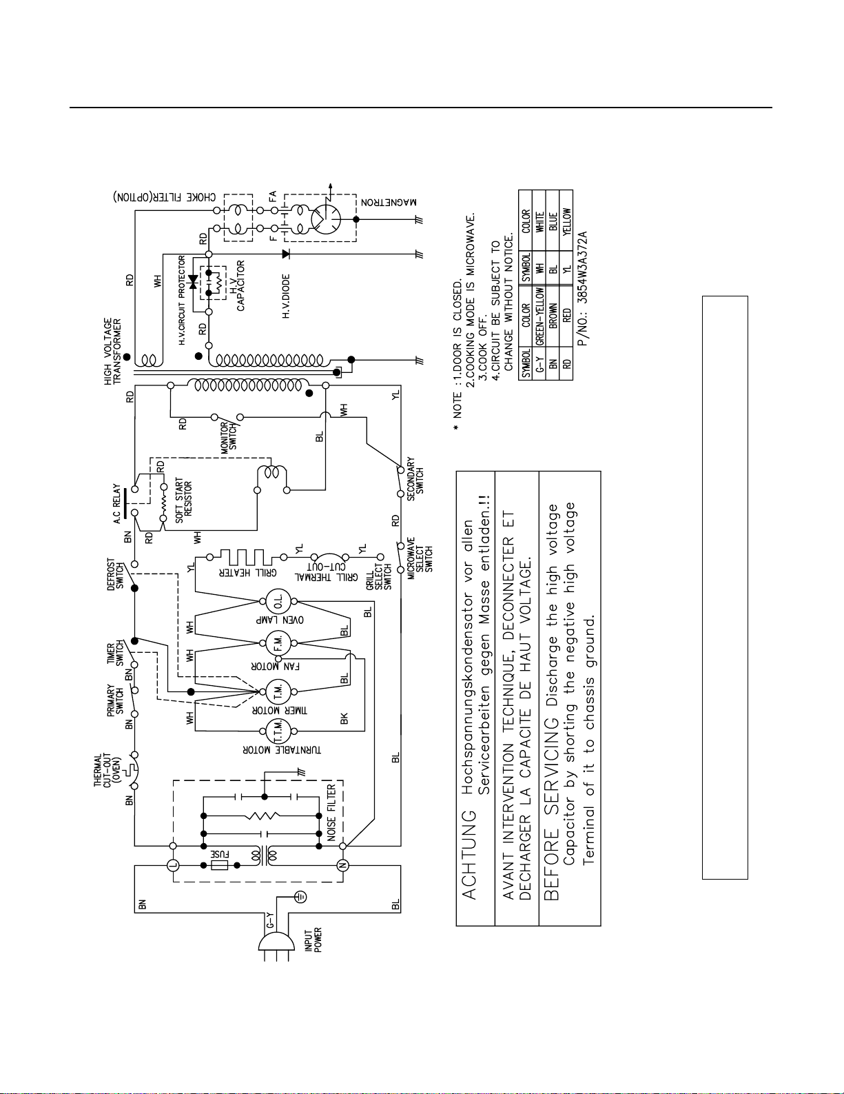
•As the door is closed, the contact of MONITOR
SWITCH opens. This switch creates the short circuit to
blow fuse during operation under abnormal condition.
(ie, should the contacts of primary and secondary
switch fail to open the circuit)
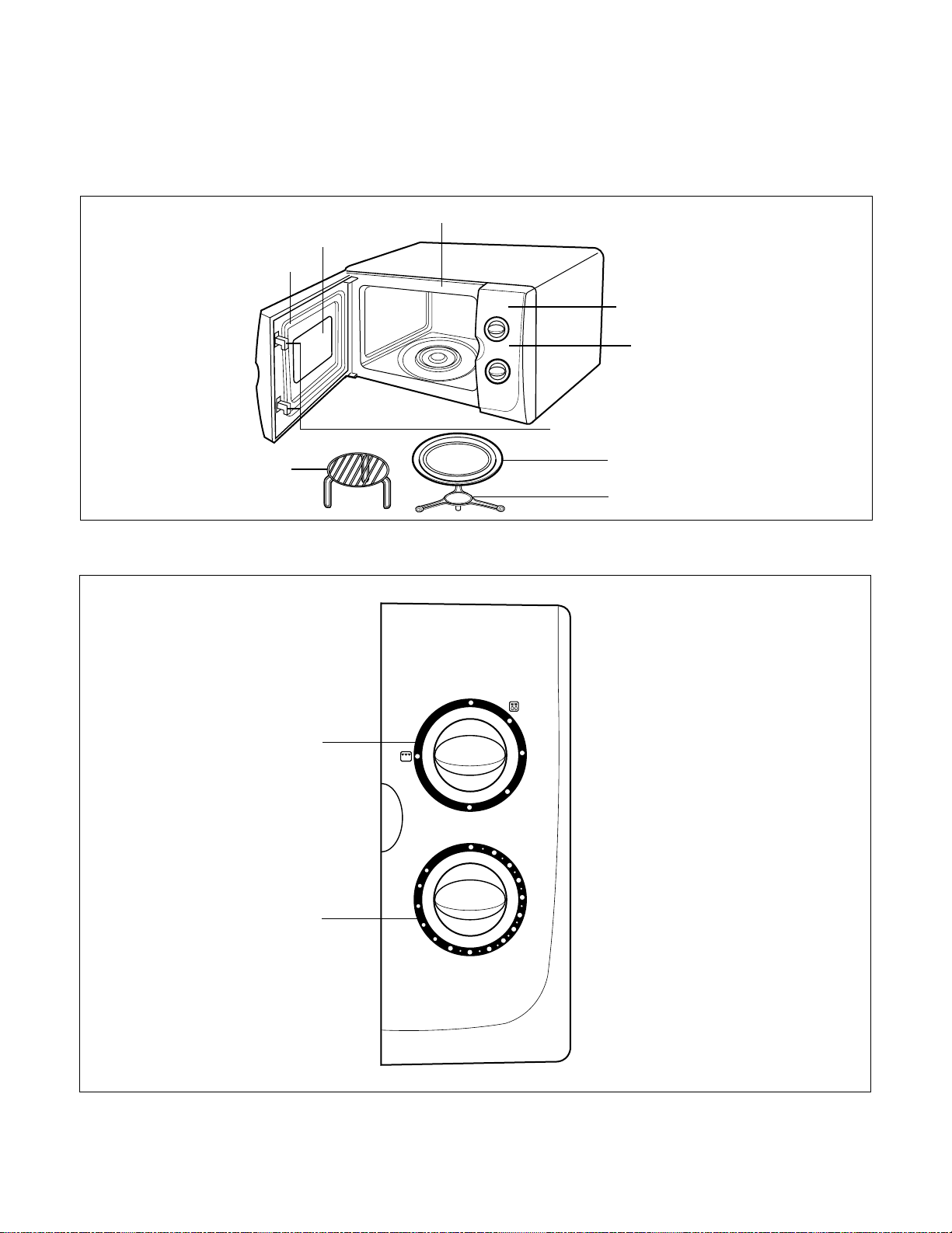
•The latches are secured by latch board. The oven light
turns on while the oven is in operation.
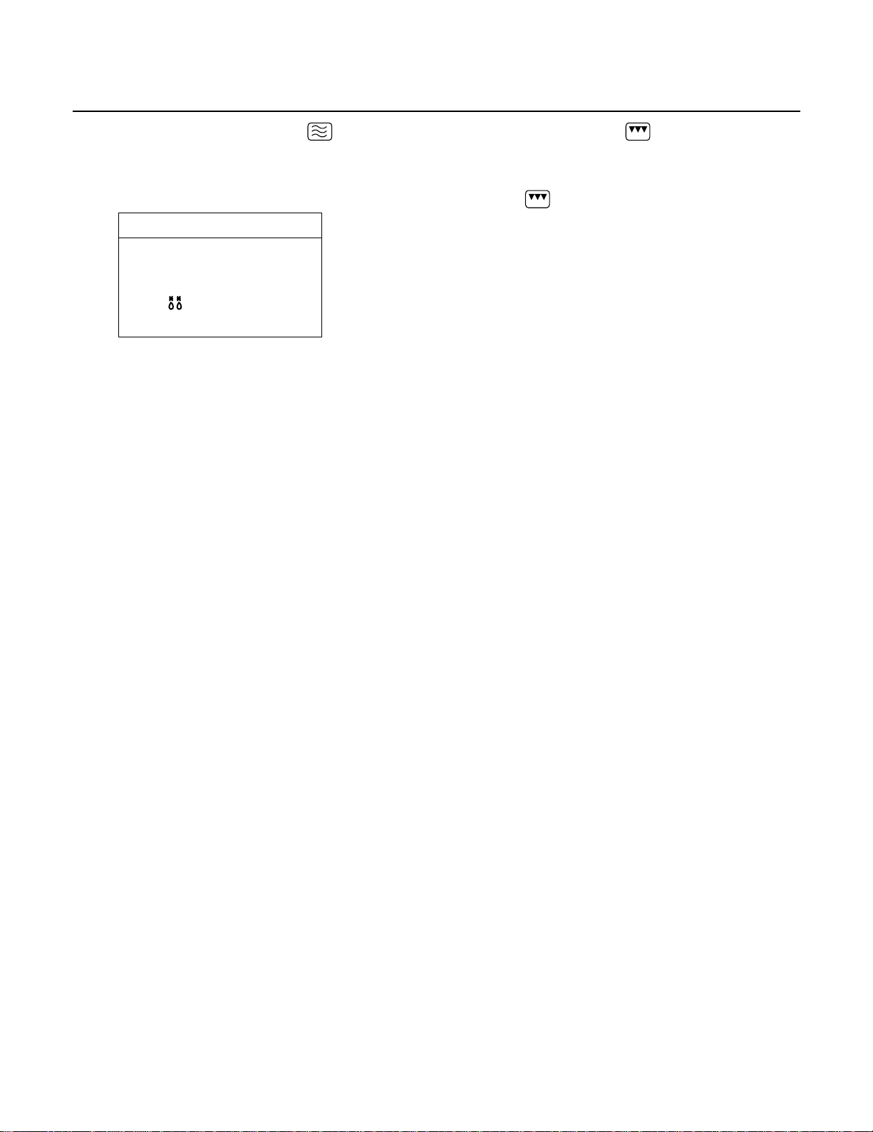
WHEN MICROWAVE POWER LEVEL
AND COOKING TIME SET
•The contacts of the timer switch changes to ON
position when the timer knob is rotated.
(While power control knob is set at “Full Power”)
•The contacts of primary and secondary switch close
the circuit.
•Input Volts AC. is applied to the high voltage
transformer through power control switch as shown by
the solid line.
•Turntable rotates.
•The fan motor rotates and cools the magnetron by
blowing the air (coming from the intake holes on the
baseplate) over the magnetron.
•The air is also directed into the oven to exhaust the
vapor in the oven through the upper plate.
•Timer starts rotating.
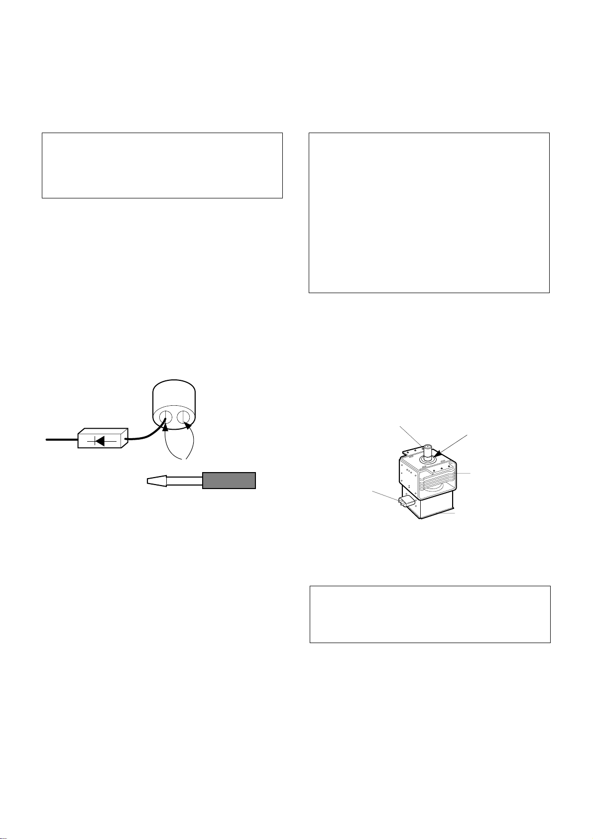
•3.2 volts AC is generated from the filament winding of
the high voltage transformer. This 3.2 volts is applied
to the magnetron to heat the magnetron filament
through two noise preventing choke coils.
A high voltage of approximately 2100 volts AC is
generated in the secondary of the high voltage
transformer which is increased by the action of the
diode and charging of the high voltage capacitor.
The negative DC voltage is then applied to the filament
of the magnetron.
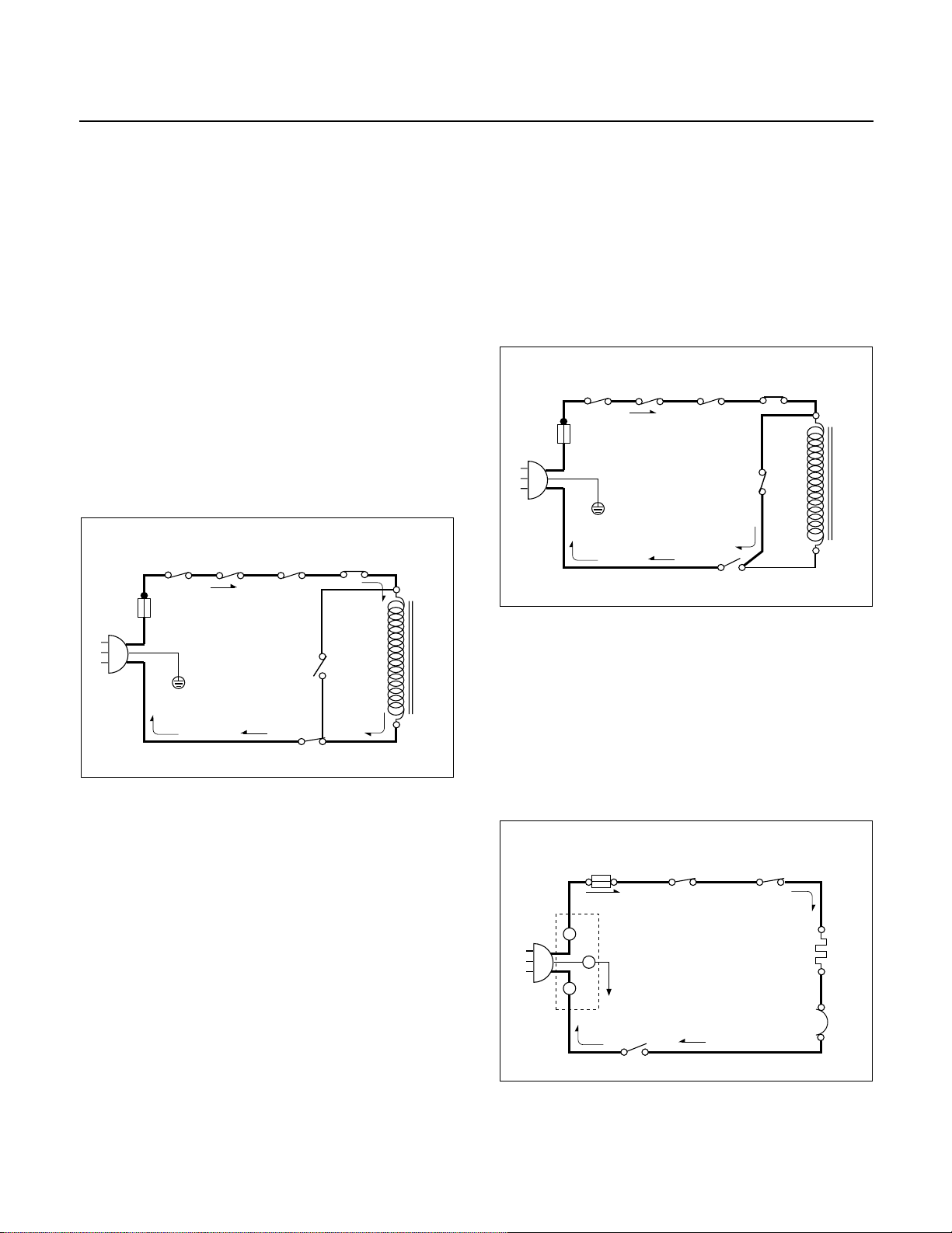
WHEN THE DOOR IS OPENED DURING
COOKING
•Both primary switch and secondary switch open to cut
off the primary winding voltage to the high voltage
transformer to stop microwave oscillation.
•Timer, turntable and fan motor stop.
•As the door is opened, if the contact of primary switch
fail to open, the fuse opens due to the large current
surge caused by the monitor switch activation which in
turn stops magnetron, oscillation.
WHEN THE GRILL COOKING FUNCTION
SELECTED
•The contacts of the timer switch change to ON
position.
•The contacts of the grill select switch close the circuit.
•Input volts AC is applied to the grill heater through
thermostat-grill as shown by the solid line.
•The fan motor and turntable rotates.
FUSE
PRIMARY
SWITCH
SECONDARY
SWITCH
MONITOR
SWITCH
L
N
H.V.T
RELAY
TIMER
SWITCH
POWER
CONTROL
SWITCH
FUSE
PRIMARY
SWITCH
SECONDARY
SWITCH
L
N
H.V.T
RELAY
TIMER
SWITCH
POWER
CONTROL
SWITCH
MONITOR
SWITCH
FUSE
PRIMARY
SWITCH TIMER
SWITCH
GRILL
SELECT
SWITCH
L
N
THERMOSTAT
GRILL
GRILL
HEATER
L
G -Y
N
E

• DO NOToperate on a 2-wire extension cord during
repair and use.
• NEVER TOUCHany oven components or wiring during
operation.
• BEFORE TOUCHING any parts of the oven, always
remove the power plug from the outlet.
• For about 30 seconds after the oven stops, an electric
charge remains in the high voltage capacitor. When
replacing or checking, you must discharge the high
voltage capacitor by shorting across the two terminals
with an insulated screwdriver.
•
Remove your watches whenever working close to or
replacing the Magnetron.
• DO NOTtouch any parts of the control panel circuit. A
resulting static electric discharge may damage this
P.C.B.
• NEVERoperate the oven with no load.
•NEVERinjure the door seal and front plate of the oven
cavity.
• NEVERput iron tools on the magnetron.
• NEVERput anything into the latch hole and the
interlock switches area.
• Proper operation of the microwave oven requires that
the magnetron be assembled to the waveguide and
cavity. Never operate the magnetron unless it is
properly installed.
• Be sure that the magnetron gasket is properly
installed around the dome of the tube whenever
installing the magnetron.
1-1
CAUTIONS
Unlike other appliances, the microwave oven is
high-voltage and high-current equipment.
Though it is free from danger in ordinary use,
extreme care should be taken during repair.
THE OVEN IS TO BE SERVICED ONLY
BY PROPERLY QUALIFIED SERVICE
PERSONNEL.
MICROWAVE RADIATION
Personnel should not be exposed to the
microwave energy which may radiate from the
magnetron or other microwave generating
device if it is improperly used or connection.
All input and output microwave connections,
waveguide, flange and gasket must be secure
never operate the device without a microwave
energy absorbing load attached.
Never look into an open waveguide or antenna
while the device is energized.
Gasket
ANTENNA
COOLING FIN
MAGNETRON
CHASSIS GROUND
FILAMENT
TERMINALS
MAGNETRON

INSTALLATIONS
1-2
INSTALLING
1. Empty the microwave oven and clean inside it with
a soft, damp cloth. Check for damage such as
misaligned door, damage around the door or dents
inside the cavity or on the exterior.
2. Put the oven on a counter, table, or shelf that is
strong enough to hold the oven and the food and
utensils you put in it. (The control panel side of the
oven is the heavy side. Use care when handling.)
3. Do not block the vent and the air intake openings.
Blocking vent or air intake openings can cause
damage to the oven and poor cooking results.
Make sure the microwave oven legs are in place to
ensure proper air flow.
4. The oven should not be installed in any area where
heat and steam are generated, because they may
damage the electronic or mechanical parts of the
unit.
Do not install the oven next to a conventional
surface unit or above a conventional wall oven.
5. Use microwave oven in an ambient temperature
less than 104°F(40°C).
6. Place the microwave oven on a sturdy and flat
surface at least 10 cm(4 inches) from the wall.
7. Place the microwave oven as far away as possible
from TV, RADIO, COMPUTER, etc., to prevent
interference.
EARTHING INSTRUCTIONS
This microwave oven is designed to be used in a fully
earthed condition.
It is imperative, therefore, to make sure it is properly
earthed before servicing
WARNING-
THIS APPLIANCE
MUST BE EARTHED
IMPORTANT
As the colors of the wires in the mains lead of this
appliance may not correspond with the colored
markings identifying the terminals in your plug,
proceed as follows.
The wire which is colored green-and-yellowmust be
connected to the terminal in the plug which is marked
with the letter Eor by the earth symbol( ) or
colored greenor green-and-yellow.
The wire which is colored bluemust be connected to
the terminal in the plug which is marked with the letter
Nor colored black.
The wire which is colored brownmust be connected
to the terminal in the plug which is marked with the
letter Lor colored red.
BEFORE YOU BEGIN, READ THE FOLLOWING INSTRUCTIONS COMPLETELY AND CAREFULLY.
10cm
The wires in this mains lead are colored in
accordance with the following code:
Green-and-yellow: Earth
Blue: Neutral
Brown: Live

DOOR PARTS
LATCH BOARD PARTS
CONTROL PANEL PARTS
INTERIOR PARTS
BASE PLATE PARTS
OVEN CAVITY PARTS
6-1
EXPLODED VIEW
INTRODUCTION

6-2
13581A
14970A
14026A
13552A 13536A
15006A
13213A
13720D
13352A
DOOR PARTS

6-3
23572A 249402
26549T
24781T
WTP
015
249401
969201
CONTROL PANEL PARTS

6-4
33112U
35264A
WTT021
WTT021
33550H
35026G
33052M
340511
34960A
34036W
36549S
WTP013
33390G
35889A
35300S
WNZ015
OVEN CAVITY PARTS

6-5
466003
466001
43501A
43500A
44510A
466002
WSZ085
LATCH BOARD PARTS

6-6
WSZ002
WTT028
WSZ002
WTT028
WSZ062
50FZZA
WSZ002
WTT037
50CZZH
56324A
55262A
54810C
56851C
56851D
55900A
56549F
56411A
56201A
56930V 56930G
568771
54974S
56912B
56201B
INTERIOR PARTS

6-7
56170D
63302A
63303A
WTT021
WSZ002
65006B
BASE PLATE PARTS
Table of contents
Other LG Microwave Oven manuals