LG KE/KL-20/21P32X User manual

CHASSIS : MV-031A
MODEL : KE/KL-20/21P32X
MODEL : KF-20/21P32
MODEL
CONTENT
PURITY & CONVERGENCE ADJUSTMENT
........3-2
ADJUSTMENT INSTRUCTIONS .................3-5
BLOCK DIAGRAM .............................................3-9
WIRING DIAGRAM ........................................ 3-10
TROUBLESHOOTING CHARTS .................3-11
PRINTED CIRCUIT BOARDS .......................3-16
COMPONENT LOCATION GUIDE .............3-17
SECTION 3 ELECTRICAL PART
TVCR
SERVICE MANUAL

3-5
ADJUSTMENT INSTRUCTIONS
1. APPLICATION RANGE
This specification is applicable to tvcr’s (MV-031Achassis)
manufactured in the tv factory or the approved site.
1.1 MAIN PRUDUCTION FORM
-. SET ( O )
-. SKD ( O )
-. CKD ( 0 )
2. DESIGNATION
2.1. Hot GND & Cold GND must be connected separately to
prevent electric shock and to protect equipments because
this chassis is an insulation chassis.
2.2. The adjustment must be done by the exact sequence.
But, it can be changeable within the allowable margin of
error.
2.3. Adjust surrounding condition: unless otherwise noted,
adjust to the following condition.
Surrouding Temperature: 25cC!5 cC
Reality Humidity : 60 % !20 %
Embedded Component Body Temperature In PCB: 25cC!5 cC
2.4. The AC line voltage of TV must be maintained at 110-230V
@50/60 Hz.(NEU AC 110V-240V)
2.5. Before any adjustment, TV set must have warming time for
15 minutes.
2.6. Necessary instrument
- Multimeter (ADJUSTMENT/ASSEMBLY Line)
Max Input Current : over 1A / Max Input Voltage : 500Vdc
Measurement Range : 10Vdc ~ 100Vdc / Accuracy : 0.03%
- Oscilloscope : (ADJUSTMENT/ASSEMBLY Line)
Frequency Band: over 20MHZ/Input Impedance: over 1MX
Input Capacitance : below 30pF / Max Input Voltage : 250V
- 10:1 PROBE
2.7. SIGNAL
Unless otherwise noted,input the STANDARD COLOR SIGNAL
60~80 dBu.
The standard color signal is LG’s standard digital signal.
It refers the standard color signal to LG standard signal.
If LG standard signal is a criterion,PAL standard signal is PAL-
B/G 05 CH and SECAM standard signal is SECAM 04CH or
40CH.
LG standard color signal has priority to others and other
vendors which use different equipment from LG can use the
PHILIPS DIGITAL PATTERN or COLOR BAR PATTERN or
CIRCLE PATTERN depend on itmes.
3. DECK LINE ADJ.
(VCR DECK/CIRCUIT ADJ.)
3.1. P2/P3 TEMPORARY ADJUSTMENT
3.1.1. NECESSARY INSTRUMENT
1. PAL SP Normal TAPE
2. OSCILLOSCOPE
3. 10:1 PROBE : 2 PIECES
4. SPECIAL NUT DRIVER (P2/P3 for Adjustment)
3.1.2. ADJUSTMENT
1. Play the PAL SP NORMAL TAPE.
2. Connect the oscilloscope(CH-1) to J123(H/SW) of main
PCB.
3. Connect the oscilloscope(CH-2) to J158(RF) of main PCB.
4. With observing the RF envelope waveform, adjust P2, P3
until it becomes the waveform C.
5. Check the envelope waveform is in the maximum size by
pressing the TRK UP(+), down(-) button.
3.2. CTL/AUDIO LEVEL ADJUSTMENT
3.2.1. NECESSARY INSTRUMENT
1. CTL TAPE
2. PAL SP Normal TAPE(AUDIO LEVEL for Adjustment)
3. OSCILLOSCOPE
4. 10:1 PROBE : 2 PIECES
5. RMS METER(AUDIO LEVEL for Adjustment)
3.2.2. CTL ADJUSTMENT
THIS ADJUSTMENT MUST BE DONE WHEN THE
UNCONTROLLED DECK IS WAREHOUSED.
1. Connect the oscilloscope to J101(CTL).
2. After playing the CTL control tape, make sure the CTL
waveform range is from 1.5 :1 to 2.5 : 1. If it is out of range ,
ADJUST PART LOCATION
TAKE-UP
REEL
AZIMUTH ADJUST SCEW X-DISTANT FIX SCREW
HEIGHT ADJUST SCREW
TILT ADJUST SCREW
CAPSTAN T/UP ARM
X-DISTANTADJUST GROOVE
PINCH-ROLLER
SUPPLY
REEL
DRUM
P2 P3
FE HEAD
P1
TENTION ARM
P4
P0
ADJUST PART LOCATION
TAKE-UP
REEL
AZIMUTH ADJUST SCEW X-DISTANT FIX SCREW
HEIGHT ADJUST SCREW
TILT ADJUST SCREW
CAPSTAN T/UP ARM
X-DISTANTADJUST GROOVE
PINCH-ROLLER
SUPPLY
REEL
DRUM
P2 P3
FE HEAD
P1
TENTION ARM
P4
P0
TAKE-UP
REEL
AZIMUTH ADJUST SCEW X-DISTANT FIX SCREW
HEIGHT ADJUST SCREW
TILT ADJUST SCREW
CAPSTAN T/UP ARM
X-DISTANTADJUST GROOVE
PINCH-ROLLER
SUPPLY
REEL
DRUM
P2 P3
FE HEAD
P1
TENTION ARM
P4
P0
P2
<A> P2 POST ADJUSTMENT
P3
<B> P3 POST ADJUSTMENT
D
<C> FINAL ADJUSTMENT WAVWFORM
P2P2
<A> P2 POST ADJUSTMENT
P3
P3
<B> P3 POST ADJUSTMENT
FIGURE 2> P2/P3 ADJUSTMENT WAVEFORM
D
<C> FINAL ADJUSTMENT WAVWFORM

3-6
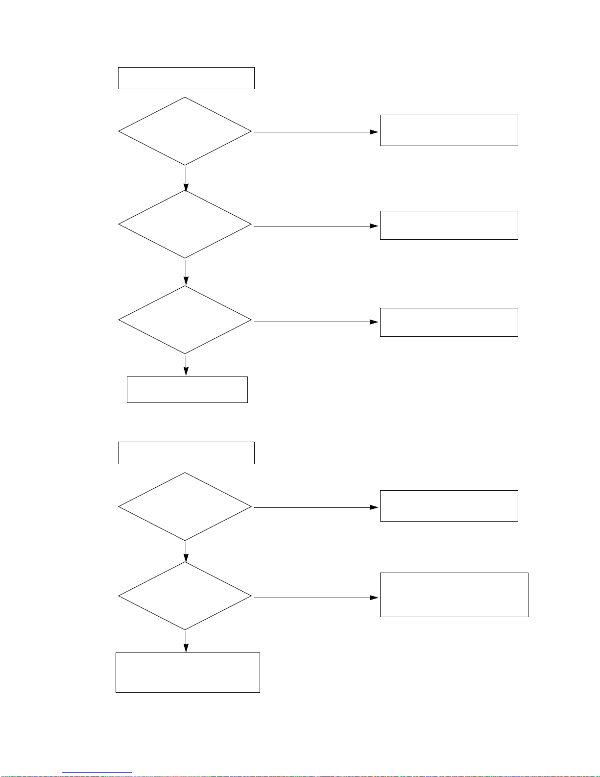
adjust CTL waveform to the following procedures.
A. If is over 2.5 :1, lower the head height.
After turning the height adjust screw counter-clockwise to
adjust its level from 1.5 : 1 to 2 : 1.
Check the tape location at P4. Readjust the TILT.(2:1)
B. If is under 1.5:1, heighten the head height.
After turning the height, adjust the screw clockwise to
adjust its level from 2 : 1 to 2.5 : 1.
Check the tape location of P4. Readjust the TILT.(2:1)
3. Play the standard tape and adjust very carefully the azimuth
screw right and left by using the oscilloscope and level-
meter to maximize the audio sound.
Adjust the azimuth screw & the height adjust screw at the
same time because they have mutual relationship. (Check
CTL again after the adjustment)
*A/C head adjustment order
Height adjust screw->check the TILT->azimuth screw
->check CTL
3.2.3 AUDIO LEVEL CHECKING AND ADJUSTMENT
1. Connect “+” terminal of RMS meter (auto level meter) to J108
on the main PCB Audio output and “-” terminal to GND.
2. Check that if audio level of RMS meter satisfies with the
spec,If audio sound is weak, adjust the A/C head azimuth
screw.
3. Audio level spec
1K :0.5 !0.1Vrms
6K :1KHz !1.5dB
3.3. X-DISTANT/P2,P3 ADJUSTMENT
3.3.1. NECESSARY INSTRUMENT
1. SP PAL TAPE
2. OSCILLOSCOPE
3. 10:1 PROBE : 2 PIECES
4.SPEACIAL DRIVER FOR ADJUSTMENT(P2,P3,X-
DISTANT(NUT),AUDIO(NUT))
5. RMS METER(AUDIO LEVEL METER)
3.3.2. ADJUSTMENT PREPARATION
1.Connect oscilloscope(CH-1) to J123(H/SW) on main PCB.
(Use for trigger of CH-2 )
2.Connect oscilloscope(CH-2) to J158(RF) on main PCB.
(Use waveform of CH-2)
3. Play by inserting SP PAL TAPE. (2hd:normal tape)
4. After the picture is appeared, make initial condition by
pressing the tracking adjustment up(+) button of the remote
controller.
3.3.3. X-DISTANCE ADJUSTMENT
1. Turn the X-distant adjust groove of the deck right and left to
maximize the scope waveform.
2. Check that if waveform satisfies with the linearity by pressing
TRK Up(+) and Down(-) button.
3. Tighten the X-distant adjust screw.
3.3.4. P2/P3(RF LINEARITY) CHECK & ADJUSTMENT
1. Adjust p2 & p3 so that the the RF envelope waveform of the
oscilloscope becomes C in figure 2.
2. Check if the envelope waveform becomes maximum by
pressing TRK Up(+),Down(-) button onestep.
3.4. PG ADJUSTMENT
Adjust it after finishing controlling the Deck.
3.4.1.NECESSARY INSTRUMENT
1. SP PAL TAPE
2. OSCILLOSCOPE
3. 10 : 1 PROBE : 2 PIECES
3.4.2. ADJUSTMENT
1. Insert and play the SP PAL TAPE.
2. Connect the oscilloscope(CH-1) to H/SW(J123) on the main
PCB and trigger in setting the VOL/DIV to 1V range.
3. Connect the oscilloscope(CH-2) to video out(J173) on the
main PCB and set the VOL/DIV to 500mV range.
4. Set the TIME/DIV of oscilloscope to 50us range.
5. Adjust the falling edge(412us !20us) of vertical sync in the
video signal by varying VR01.
4.ASSEMBLY LINE ADJUSTMENT
4.1. RF AGC ADJ.( APPLYING THE W/S TUNER )
4.1.1. NECESSARY INSTRUMENT : DIGITAL MULTIMETER
4.1.2. ADJUSTMENT PREPARATION
1. HEAT-RUN at least 15 minutes before adjustment.
2. Input the PAL DIGITAL PATTERN(EU05); The intensity of
electric field for the applied tuner refers to the below data.
3. Connect the DIGITAL MULTIMETER to TP-AGC(J335) of
MAIN1.
4.1.3. ADJUSTMENT
1. Press the SVC key of the transmitter and select¡AGC¡–of the
SVC MENU using PR+/- key.
2. Adjust it by the below data varying VOL+/- key.
4.2. FOCUS ADJUSTMENT
4.2.1. Receive the standard color signal.
4.2.2. Let the picture be the most clear by the criterion of the
vertical line of it, varying the focus V/R of FBT.
12
CTL WAVEFORM
12
CTL WAVEFORM
12
CTL WAVEFORM
ADJUST PERIOD (6.5H = 412us)
PG ADJUST WAVEFORM
*CAUTION: SET THETRIGGER MODE OF OSCILLOSCOPETO DC
ADJUST PERIOD (6.5H = 412us)
PG ADJUST WAVEFORM
*CAUTION: SET THETRIGGER MODE OF OSCILLOSCOPE TO DC
TUNER
6700VPF009V
6700VMF001H
6700VPF009Q
Electric fields strenth
AGC Voltage
AGC Voltage
70dBu ! 1dBu
2.7 ! 0.05Vdc
AGC not adjust.
Setting & Adjustment

4.3. PURITY AND CONVERGENCE ADJUSTMENT
: Warm up the TV set at least 15 minutes before adjustment.
4.3.1. PURITY ADJUSTMENT
1. After degaussing the CPT with using the degaussing coil, set
the picture at Standard ON.
2. Receive the raster signal or E50CH(red pattern) from a
pattern generator.
3. Move the DY toward CPT PANEL to put the picture like the
figure 5.
4. Turn the purity magnet(the second pole magnet) to let red
color located at the center of picture. At the same time let
color-line located at the center vertically.
5. After finishing the second pole magnet adjustment, fix it
temporarily by the lock ring.
6. Let the picture became uniform red color by moving the DY
slowly backward and then tighten the fixing screw. (Check
the slope)
4.4. SCREEN ELECTRIC VOLTAGE
1. Input PAL DIGITAL PATTERN(EU05 CH).
2. Select CHANNEL 0.
3. Connect the probe of oscilloscope to the RK of CPT PCB.
4. Set the oscilloscope to 50V/DIV, 20us/DIV(using 10:1 Probe )
and after putting the GND ling upon the lowest grid line of the
scope by pushing the GND button, enter into DC
mode.
* Adjust screen volume of FBT so that the waveform is the same
as below figure.
4.5 WHITE BALANCE
4.5.1 NECESSARY INSTRUMENT
: WHITE BALANCE METER
4.5.2 ADJUST PREPARATION
1. Adjust it after warming up the meter over 20 minutes.
2. Input the picture with the white signal and black signal at
upper and lower side each in a standard of the CPT’s
horizontal center.
3. Set this picture in the status of standard ON.
4.5.3 ADJUSTMENT
: Press the SVC key of a transmitter which is possible to control
the SVC and adjust the RG and BG varying the VOL +/-, in the
status of the initial data 32 of the CG in SVC MENU on the
screen. (This chassis adjusts only the high light.)
4.6. DEFLECTION DATA ADJUSTMENT
4.6.1. Input PAL DIGITAL PATTERN(EU05CH).
4.6.2. Press SVC key on the service remote controller and
select LINE SERVICE 2 mode.Adjustable item is selected
by CH+/- key,variable item is selected by VOL +/- key.
4.6.3. Deflection Early Establishment Data
4.6.4.VERTICAL SLOPE, V-SLP ADJUSTMENT
Select V-SLP mode and adjust until horizontal center line of
the large circle coincides with blanking line
4.6.5. VERTICAL AMPLITUDE, V-AMP ADJUSTMENT
Select V-AMP mode , and adjust until the upper and lower
end of the large circle reach 5mm inside from the effective
area of CPT.
4.6.6. VERTIVAL SHIFT, V-SFT ADJUSTMENT
Select V-SFT mode and adjust until the horizontal center
coincides with the vertical sign Slot mark of CPT.
4.6.7. HORIZONTAL SHIFT, H-SFT ADJUSTMENT
Select H-SFT mode and adjust until the vertical center
coincides with horizontal sign slot mark of CPT.
4.6.8. VERTICAL S-CORRECTION, S-COL ADJUSTMENT
Select S-COL mode and adjust until the grid of cross hatch
pattern is even all over the screen.
R BGG
< figure 5 >
PICTURE STANDARD ON
CONTRAST : 85%
BRIGHTNESS : 70%
COLOUR : 50%
140V BLACK LEVEL(DC)
GND
V
140V BLACK LEVEL(DC)
GND
V
No
1
2
140V !3V
130V !3V 21/20/15” CPT
14” CPT
Adjust Voltage Remark Note
Model(14/20/21)
EU
NON-EU
9000K
10000K
288
281
295
288
X Y Color Temperature
Model(15 FLAT )
EU
NON-EU
9000K
12000K
288
272
295
288
X Y Color Temperature
Status
V-SLP
V-AMP
V-SFT
H-SFT
S-COL
Vertical Slope
Vertical Amplitude
Vertical Shift
Horizontal Shift
Vertical S-correction
25
31
32
32
15
25
31
32
32
15
25
31
32
32
15
25
31
32
32
15
Adjust Cintents 15”21” 20” 14”
3-7

4.7. CDL DATA ADJUSTMENT
1. Input PAL DIGITAL PATTERN(EU05CH).
2. Press SVC key on the service remote controller and select
LINE SERVICE 1 mode.
Adjustable item is selected by CH+/- key,variable item is
selected by VOL +/- key
3. Initial Establishment Data
* 2nd SIF OPTION
4.8. LANGUAGE
Status
AGC
GG
RG
BG
PEAK
CDL
2nd SIF
RF Gain
Green Drive Gain
Red Drive Gain
Blue Drive Gain
Peaking Control
Cathode Drive Level
2nd SIF
15
32
32
32
25
10
0
15
32
32
32
25
08
0
15
32
32
32
25
12
0
15
32
32
32
25
12
0
Ccntents 15”21” 20” 14”
Mode
0
1
2
OFF
BG
DK
INternal BPF
BG : EXTERNAL DK/I:INTERNAL BPF
DK: EXTERNAL BG/I:INTERNAL BPF
Funtion Remark Note
No
1
2
3
4
FRANCE
GERMANY
Other EU
Except EU
FRENCH
GERMAN
ENGLISH
ENGLISH
If buyer request special
language we can
accept it.
Country Language Remark Note
3-8

3-9
BLOCK DIAGRAM

3-11
Is there about 6V
at pin 9 of P804?
YES
Is there about 11V
at '+' terminal
of C856?
YES
Is there about 6.1V
at pin 9 of IC801?
YES
Is there voltage at
pin 9 of T801?
YES
NO POWER : NO STAND-BY
Replace the Fuse
Check the 6V Line
of MAIN 1 BOARD
Check if the
Fuse is O.K.?
YES
NO
Check/Replace
DB801, R801, C806.
NO
Check/Replace
D806, Q801, R807, ZD801, C814,
IC801.
NO
¡Check/Replace FR851, D852,
C856, Q860, Q861, Q862,
ZD860, ZD861, R874.
¡Check the pin 11 of P804 :
'LOW"
NO
Check/Replace
IC857, D856, F852, C875
NO
TROUBLE SHOOTING

3-12
Is there about 115V
at '+' terminal of C865?
YES
Is there about
6V at pin 9 of P804?
YES
NO POWER : NO MONITOR ON
Go to NO POWER (NO ST-BY)
BLOCK
Go to NO RASTER BLOCK
Check T701, Q781 and go to
NO RASTER BLOCK
Check the
NO POWER(NO ST-BY)
BLOCK
YES
NO
Check the pin 10 of P804 ; "HIGH"
NO
¡Check/Replace D851, L851,
C860, IC851.
¡Check the pin 10 of P804 :
'HIGH"
NO

3-13
Is there about
6.3VAC at HEATER of CPT
SOCKET?
YES
Does the waveform
appear at the collector
of Q781?
YES
Does the square
waveform appear at pin 1 of
P805?
YES
Is there about 8V
at pin 6 of P805?
YES
NO RASTER
Go to NO POWER BLOCK
Go to NO PICTURE BLOCK
Is there about 115V
at pin 3 of T701?
YES
NO
¡Check/Replace F852, D850,
R858, IC853, C863.
¡Check the 8V LINE of VCD
BOARD
NO
¡Check the H-OUT LINE of VCD
BOARD.
¡Check/Replace IC501 of VCD
BOARD.
NO
Check/Replace Q782, T781, R783,
Q781.
NO
Check/Replace T701, 5PIN
CONNECTOR, FR901,FR902.
NO

3-14
Is there about
-14V at pin 1 of IC701?
YES
Is there about
14V at pin 6 of
IC701?
YES
V. Deflection ERROR
Check the vertical part of VCD
Check/Replace IC701
Does the V-A, V-B
signal appear at pin 4, 7
of P805?
YES
NO
Check/Replace FR702, D703, C703.
Check;/Replace FR701, D702, C704.
NO
Is there about
185V at pin 1 of P902?
YES
NO PICTURE
Check the CVBS line of VCD
¡Check/Replace IC901.
¡Check screen voltage
Does the RGB signal
appear at pin 3, 5, 7 of
P901A?
YES
NO
Check/Replace D701, C701, T701, 5PIN
CONNECTOR.
NO
NO

3-15
Does the sound
signal appear at pin 4
of IC601?
YES
Does the sound
signal appear at pin 9
of P805?
YES
NO SOUND
Check/Replace FR854, D855, IC601.
Check/Replace speaker,
speaker connector.
Is there about
25V at pin 5
of IC601?
YES
NO
Check the Audio source line of
VCD
¡Check the voltage at collector of
Q602.
¡Check/Replace IC601, external
components of IC601.
NO
NO

P/No : 3854VA0110A-S(1/2)
2003.03.14

P/No : 3854VA0110A-S(2/2)
2003.03.14
This manual suits for next models
1
Table of contents
Other LG TV VCR Combo manuals