LG 42PC56 User manual

PLASMA TV
SERVICE MANUAL
CAUTION
BEFORE SERVICING THE CHASSIS,
READ THE SAFETY PRECAUTIONS IN THIS MANUAL.
CHASSIS : PD73A
MODEL : 42PC56 42PC56-ZD
website:htt ://biz.LGservice.com

- 2 -
CONTENTS
SAFETY PRECAUTIONS ....................................................................................3
SPECIFICATIONS ................................................................................................4
ADJUSTMENT INSTRUCTIONS .........................................................................6
TROUBLE SHOOTING GUIDE..........................................................................19
BLOCK DIAGRAM.............................................................................................29
EXPLODED VIE ..............................................................................................30
EXPLODED VIE PARTS LIST ........................................................................31
REPLACEMENT PARTS LIST...........................................................................32
SCHEMATIC DIAGRAM.........................................................................................
PRINTED CIRCUIT DIAGRAM ..............................................................................

- 3 -
SAFETY PRECAUTIONS
Many electrical and mechanical parts in this chassis have special safety-related characteristics. These parts are identified by in the
Schematic Diagram and Replacement Parts List.
It is essential that these special safety parts sh uld be replaced with the same c mp nents as rec mmended in this manual t prevent
X-RADIATION, Sh ck, Fire, r ther Hazards.
D n t m dify the riginal design with ut permissi n f manufacturer.
General Guidance
An isolation Transformer should always be used during the
servicing f a receiver wh se chassis is n t is lated fr m the AC
p wer line. Use a transf rmer f adequate p wer rating as this
pr tects the technician fr m accidents resulting in pers nal injury
fr m electrical sh cks.
It will als pr tect the receiver and it's c mp nents fr m being
damaged by accidental sh rts f the circuitry that may be
inadvertently intr duced during the service perati n.
If any fuse ( r Fusible Resist r) in this m nit r is bl wn, replace it
with the specified.
When replacing a high wattage resist r (Oxide Metal Film Resist r,
ver 1W), keep the resist r 10mm away fr m PCB.
Keep wires away fr m high v ltage r high temperature parts.
Due t high vacuum and large surface area f picture tube,
extreme care sh uld be used in handling the Picture Tube.
D n t lift the Picture tube by it's Neck.
Leakage Current Cold Check(Antenna Cold Check)
With the instrument AC plug rem ved fr m AC s urce, c nnect an
electrical jumper acr ss the tw AC plug pr ngs. Place the AC
switch in the n p siti n, c nnect ne lead f hm-meter t the AC
plug pr ngs tied t gether and t uch ther hm-meter lead in turn t
each exp sed metallic parts such as antenna terminals, ph ne
jacks, etc.
If the exp sed metallic part has a return path t the chassis, the
measured resistance sh uld be between 1MΩ and 5.2MΩ.
When the exp sed metal has n return path t the chassis the
reading must be infinite.
An ther abn rmality exists that must be c rrected bef re the
receiver is returned t the cust mer.
Leakage Current Hot Check (See below Figure)
Plug the AC c rd directly int the AC utlet.
Do not use a line Isolation Transformer during this check.
C nnect 1.5K/10watt resist r in parallel with a 0.15uF capacit r
between a kn wn g d earth gr und (Water Pipe, C nduit, etc.)
and the exp sed metallic parts.
Measure the AC v ltage acr ss the resist r using AC v ltmeter
with 1000 hms/v lt r m re sensitivity.
Reverse plug the AC c rd int the AC utlet and repeat AC v ltage
measurements f r each exp sed metallic part. Any v ltage
measured must n t exceed 0.75 v lt RMS which is c rresp nds t
0.5mA.
In case any measurement is ut f the limits specified, there is
p ssibility f sh ck hazard and the set must be checked and
repaired bef re it is returned t the cust mer.
Leakage Current Hot Check circuit
1.5 K hm/10W
T Instrument's
exp sed
METALLIC PARTS
G d Earth Gr und
such as WATER PIPE,
CONDUIT etc.
AC V lt-meter
IMPORTANT SAFETY NOTICE
0.15uF

SPECIFICATIONS
NOTE : Specifications and others are subject to change without notice for improvement
.
VApplication Range
This spec is applied to the 42” PL SM TV used PD73 Chassis.
V Specification
Each part is tested as below without special appointment.
1) Temperature : 25±5°C (77±9°F), CST : 40±5
2) Relative Humidity: 65±10%
3) Power Voltage: Standard Input voltage (100-240V~, 50/60Hz)
* Standard Voltage of each product is marked by models.
4) Specification and performance of each parts are followed each drawing and specification by part number in accordance with SBOM.
5) The receiver must be operated for about 20 minutes prior to the adjustment.
VTest Method
1) Performance : LGE TV test method followed.
2) Demanded other specification
Safety : CE, IEC specification
EMC : CE, IEC
VGeneral Specification
1. Mod le Specification ( 42” XGA MODULE )
- 4 -
Display Screen Device
spect Ratio
PDP Module
Operating Environment
Storage Environment
Input Voltage
1
2
3
4
5
6
No Item Specification Remark
42” Wide Color Display Module
16:9
PDP42X4,
RGB Closed Type, Film Filter
1)Temp. : 0~40deg
2)Humidity : 20~80%
3)Temp. : -20~60deg
4)Humidity : 10~90%
100-240V~, 50/60Hz
Plasma Display Panel
LGE SPEC.
Maker LG
Chassis
PD73 42PC56-ZD UK, German, Italy, France, Sweden, Finland, Spain LG
Model Name Market Brand Remark
42PC56-ZD
Safety : IEC/EN60065
EMI : EN55013
EMS : EN55020
UK, German, Italy, France, Sweden, Finland, Spain TEST
Model pplianceMarket Remark

- 5 -
2. Model General Specification
Market
Br adcasting system
Receiving system
Scart Jack (2EA)
Vide Input (1EA)
S-Vide Input (1EA)
C mp nent Input (1EA)
RGB Input(1EA)
HDMI Input(2EA)
Audi Input (3EA)
1
2
3
4
5
6
7
8
9
10
N Item Specificati n Remark
UK, German, Italy, France, Sweden, Finland, Spain
1) PAL-BG
2) PAL-DK
3) PAL-I,I’
4) DVB-T(ID TV)
5) SECAM-L/L’
Anal g : Upper Heter dyne
Digital : COFDM
PAL, SECAM
PAL, SECAM, NTSC
PAL, SECAM, NTSC
Y/Cb/Cr, Y/Pb/Pr
RGB-PC
HDMI-DTV & SOUND
PC Audi , C mp nent, AV
4 System : PAL, SECAM, NTSC, PAL60
L/R Input

- 6 -
ADJUSTMENT INSTRUCTIONS
1. Application Object
These instructi ns are applied t all f the 42” PLASMA TV,
PD73A Chassis.
2. Note
(1) Because this is n t a h t chassis, it is n t necessary t use
an is lati n transf rmer. H wever, the use f is lati n
transf rmer will help pr tect test instrument.
(2) Adjustment must be d ne in the c rrect rder.
(3) The adjustment must be perf rmed in the circumstance f
25±5°C f temperature and 65±10% f relative humidity if
there is n specific designati n.
(4) The input v ltage f the receiver must keep 100-240V~,
50/60Hz.
(5) The receiver must be perated f r ab ut 15 minutes pri r
t the adjustment.
OAfter RGB Full white HEAT-RUN M de, the receiver must
be perated pri r t adjustment.
OEnter int HEAT-RUN MODE
1) Press the POWER ON KEY n R/C f r adjustment.
2) OSD display and screen display PATTERN MODE.
[Set is activated HEAT-RUN with ut signal generat r in
this m de.
[Single c l r pattern(RED/BLUE/GREEN) f HEAT-RUN
m de uses t check PANEL.
3. Channel memory Setting Method
: Y u can set channel mem ry by R/C f r adjustment.
1) Press ADJ key n R/C f r adjustment.
2) Press ENTER key n “System C ntr l3”.
3) Press VOL + key n “Channel Rec ver”.
4. PCMCIA CARD Checking Method
: Y u must adjust DTV 29 Channel and insert PCMCIA CARD
t s cket.
1) If PCMCIA CARD w rks n rmally, n rmal signals display
n screen.
But it w rks abn rmally, “N CA m dule” w rds display n
screen.
5. PO ER PCB Assy Voltage
Adjustments (Va, Vs V ltage adjustments)
5-1. Test Equipment : D.M.M. 1EA
5-2.Connection Diagram for Measuring
: refer t Fig.1
5-3. Adjustment Method
(1) Va Adjustment
1) After receiving 100% Full White Pattern, HEAT RUN.
2) C nnect + terminal f D.M.M t Va pin f P812, c nnect
- terminal t GND pin f P812.
3) After turning VR901, v ltage f D.M.M adjustment as
same as Va v ltage which n label f panel right/t p.
(Deviati n; ±0.5V)
(2) Vs Adjustment
1) C nnect + terminal f D.M.M t Vs pin f P812, c nnect
– terminal t GND pin f P812.
2) After turning VR951, v ltage f D.M.M adjustment as
same as Va v ltage which n label f panel right/t p.
(Deviati n; ±0.5V)
If y u turn n a still screen m re than 20 minutes (Especially
Digital pattern, Cr ss Hatch Pattern), an afterimage may ccur
in the black level part f the screen.
Each PCB assembly must be checked by check JIG set.
(Because p wer PCB Assembly damages t PDP M dule,
especially be careful)
(Fig. 1) C nnecti n diagram f p wer adjustment f r measuring
<42” EAY32808901>
<42” 6709900019A>

- 7 -
6. EDID (The Extended Display
Identification Data)/ DDC (Display
Data Channel) download
6-1. Required Test Equipment
1) Adjusting PC with S/W f r writing EDID Data.(S/W : EDID
TESTER Ver.2.5)
2) A Jig f r EDID D wnl ad
3) Cable : Serial(9Pin r USB) t D-sub 15Pin cable, D-sub
15Pin cable, DVI t HDMI cable
6-2. Setting of device
6-3. Preparation for Adjustment
1) As ab ve Fig. 2, C nnect the Set, EDID D wnl ad Jig, PC
& Cable.
2) Turn n the PC & EDID D wnl ad Jig. And Execute the
S/W : EDID TESTER Ver,2.5.
3) Set up S/W pti n.
Repeat Number : 5
Device Address : A0
PageByte : 8
4) P wer n the Set.
6-4. Sequence of Adjustment
- EDID Download
1) Init the data.
2) L ad the EDID data.(Open File).
[Anal g file] (f r RGB)
[Digital file] (f r HDMI)
3) Set the S/W as bel w.
4) Push the “Write Data & Verify”butt n. And c nfirm “Yes”.
5) If the writing is finished, y u will see the “OK” message.
6) If TV has tw HDMI, y u must d wnl ad tw times f r
each HDMI.
(Fig. 2) C nnecti n Diagram f DDC d wnl ad
Open FileOpen File

- 8 -
- EDID DATA
1) Anal g RGB.
=> Detail EDID Opti ns are bel w([1], [2], [3],[4], [5])
1. [1]-Pr duct ID
2. [2]-Serial N : C ntr lled n pr ducti n line
3. [3]-M nth, Year : C ntr lled n pr ducti n line
ex) Week : '03' => '03'
Year : '2006' => '10'
4. [4]-M del Name(Hex):
5. [5]-Checksum : Changeable by t tal EDID data
2) HDMI1.
=> Detail EDID Opti ns are bel w([1], [2], [3],[4], [5])
1. [1]-Pr duct ID
2. [2]-Serial N : C ntr lled n pr ducti n line
3. [3]-M nth, Year : C ntr lled n pr ducti n line
ex) Week : '03' => '03'
Year : '2006' => '10'
4. [4]-M del Name(Hex):
5. [5]-Checksum : Changeable by t tal EDID data
3) HDMI2.
=> Detail EDID Opti ns are bel w([1], [2], [3],[4], [5])
* Please refer HDMI1
M del
Name
42PC55-ZB
42PC56-ZD
50PC55-ZB
50PC56-ZD
50PB56-ZA
Pr duct ID
Pr duct ID EDID table
B19C
B39C
5FC3
61C3
63C3
Hex
9CB1
9CB3
C35F
C361
C363
40013
40015
50015
50017
50019
M del Name
42PC55-ZB
42PC56-ZD
50PC55-ZB
50PC56-ZD
50PB56-ZA
Hex Data
00 00 00 FC 00 34 32 50 43 35 35 2D 5A 42 0A 20 20 20
00 00 00 FC 00 34 32 50 43 35 36 2D 5A 44 0A 20 20 20
00 00 00 FC 00 35 30 50 43 35 35 2D 5A 42 0A 20 20 20
00 00 00 FC 00 35 30 50 43 35 36 2D 5A 44 0A 20 20 20
00 00 00 FC 00 35 30 50 42 36 35 2D 5A 41 0A 20 20 20
12
3
4
5
12
3
4
5
5
M del
Name
42PC55-ZB
42PC56-ZD
50PC55-ZB
50PC56-ZD
50PB56-ZA
Pr duct ID
Pr duct ID EDID table
B29C
B49C
60C3
62C3
64C3
Hex
9CB2
9CB4
C360
C362
C364
40114
40116
50016
50018
50020
M del Name
42PC55-ZB
42PC56-ZD
50PC55-ZB
50PC56-ZD
50PB56-ZA
Hex Data
00 00 00 FC 00 34 32 50 43 35 35 2D 5A 42 0A 20 20 20
00 00 00 FC 00 34 32 50 43 35 36 2D 5A 44 0A 20 20 20
00 00 00 FC 00 35 30 50 43 35 35 2D 5A 42 0A 20 20 20
00 00 00 FC 00 35 30 50 43 35 36 2D 5A 44 0A 20 20 20
00 00 00 FC 00 35 30 50 42 36 35 2D 5A 41 0A 20 20 20
12
3
4
5
5

- 9 -
7. ADC Calibration
8. Auto AV(CVBS) Color Balance
8-1. Requirement
VThis AV c l r balance adjustment sh uld be perf rmed
bef re white Balance Adjustment.
8-2. Required Equipment
1) Rem te c ntr ller f r adjustment.
2) MSPG-925FS Pattern Generat r (Which has Vide Signal:
7 C l r Bar Pattern sh wn in Fig. 3).
- M del: 202 / Pattern: 65 EC and FC m del use PAL-
BGDHI. (c mp site signal)
8-3. Method of Auto AV(CVBS) Color Balance
1) Input the Vide signal: 7 c l r Bar signal int AV3.
2) Set the PSM t Dynamic m de in the Picture menu.
3) Press IN-STAR key n R/C f r adjustment.
4) Press the G(V l. +) key perate t set, then it bec mes
aut matically.
5) Aut -RGB OK means c mpleted adjustment.
9. Adjustment of Component
9-1. Requirement
VThis AV c l r balance adjustment sh uld be perf rmed
bef re white Balance Adjustment.
9-2. Required Equipment
1) Rem te c ntr ller f r adjustment.
2) MSPG-925FS Pattern Generat r (Which has Vide Signal:
7 C l r Bar Pattern sh wn in Fig. 4).
- M del: 215 / Pattern: 65
9-3. Method of Auto Component Color Balance
1) Input the C mp nent 720p/50Hz 7 C l r Bar(MSPG-925FS
m del:215, pattern:65) signal int C mp nent.
2) Set the PSM t Dynamic m de in the Picture menu.
3) Press IN-STAR key n R/C f r adjustment.
4) Press the G(V l. +) key perate t set, then it bec mes
aut matically.
5) Aut -RGB OK means c mpleted adjustment.
10. Adjustment of RGB
10-1. Requirement
VThis AV c l r balance adjustment sh uld be perf rmed
bef re white Balance Adjustment.
10-2. Required Equipment
1) Rem te c ntr ller f r adjustment.
2) MSPG-925FS Pattern Generat r (Which has Vide Signal:
7 C l r Bar Pattern sh wn in Fig. 5).
- M del: 215 / Pattern: 65
10-3. Method of Auto RGB Color Balance
1) Input the PC 1024x768 @ 60Hz 7 c l r bar (MSPG-925FS,
M del:3, Pattern: 65) int RGB. (using D-sub t D-sub
cable)
2) Set the PSM t Dynamic m de in the Picture menu.
3) Press IN-STAR key n R/C f r adjustment.
4) Press the G(V l. +) key perate t set, then it bec mes
aut matically.
5) Aut -RGB OK means c mpleted adjustment.
MSPG925FS
C mp nent RGB-PCRF/AV/S-VIDEOADC
M del : 3
(1024*768 60Hz)
Pattern : 65
7 C l r Bar
M del:215(720P)
Pattern : 65
* 720/50Hz
7 C l r Bar
PAL
INPUT SELECT AV3
M del : 202
(PAL-BGDHI)
Pattern : 65
* PAL 7 C l r Bar
- System c ntr l RS-232 H st sh uld be “PC“ f r adjustment.
- Bef re AV ADC Calibrati n, execute the “Panel size selecti n“
(Fig. 4) C l r bar Test Pattern
(Fig. 3) C l r Balance signal
(Fig. 5) C l r bar Test Pattern

- 10 -
11. Adjustment of hite Balance
11-1. Requirement
VBef re adjusting White-balance , the AV ADC sh uld be
d ne.
11-2. Required Equipment
1) Rem te c ntr ller f r adjustment.
2) C l r Analyzer.( CA-1000,CA-100+,CA-200 r same
pr duct ) : CH10(PDP)
* Please adjust CA-210, CA-100+ by CS-1000 before
measuring.
3) Aut W/B adjustment instrument.( nly f r Aut adjustment)
4) AV Pattern Generat r.
W Synchr nizati n relati n between PSM and CSM.
W
CS-1000/CA-100+/CA-210 White balance adjustment c rdinate
and c l r temperature.
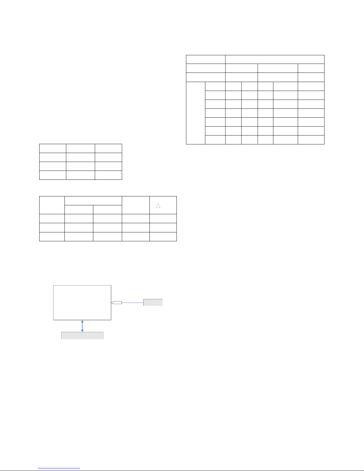
11-3. Connection Picture of the Measuring
Instrument(On Automatic control)
V Inside PATTERN is used when W/B is c ntr lled. C nnect
t aut c ntr ller r push c ntr l R/C IN-START -> Enter
the m de f White-Balance, the pattern will c me ut.
V Aut -c ntr l interface and directi ns
1. Adjust in the place where the influx f light like fl dlight
ar und is bl cked.(illuminati n is less than 10ux)
2. Measure and adjust after sticking the C l r Analyzer(CA-
100+, CA210) t the side f the m dule.
3. Aging time : keep white pattern using inside pattern.
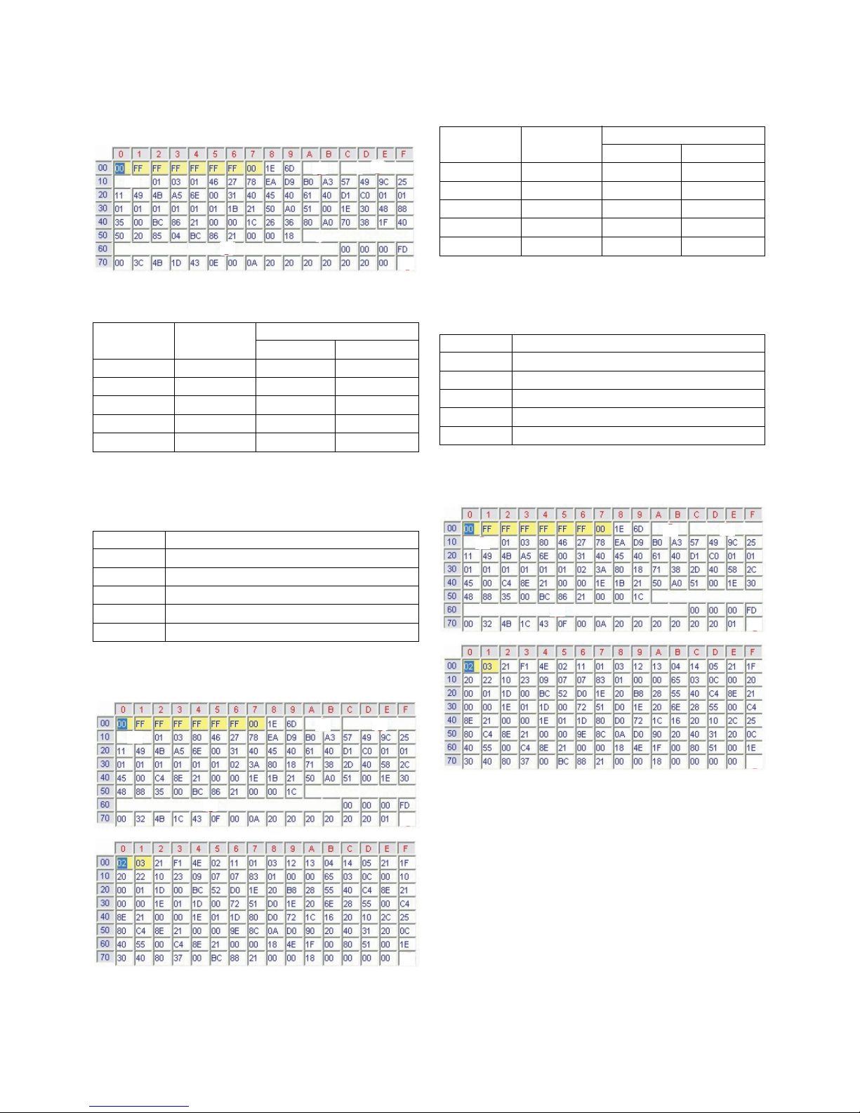
WAut adjustment Map(RS-232C)
12. Adjustment of hite Balance
(Manual white Balance)
V One f R Gain/ G Gain/ B Gain sh uld be kept n 80, and
thers are c ntr lled l wering fr m 80
(1) ‘p wer n’ f the c ntr l R/C, set heat run t white by
pressing and heat run ver 15 minutes. (Set: RS-232 H st:
PC, Baud Rate: 115200bps, D wnl ad: C rtez)
(2) Zer Calibrate CA-100+, and stick the sens r t the center
f PDP m dule surface when y u adjust.
(3) D uble click In-start key n C ntr lling R/C and get in
‘white balance’.
(4) Set test-pattern n and display inside pattern. C ntr l is
carried ut n three c l r temperature, COOL, MEDIUM,
WARM. (C ntr l is carried ut three times.)
(5) When the R/G/B GAIN is 80 n OSD, it is the FULL
DYNAMIC Range f the M dule. In rder t c ntr l white
balance with ut the saturati n f FULL DYNAMIC Range
and DATA, ne f R Gain / G Gain / B Gain sh uld be kept
n 80, and ther tw is c ntr lled l wering fr m 80.
* C l r Temperature: C l, Medium, Warm
(1) When R GAIN is set t 80
- C ntr l G GAIN and B GAIN by l wering fr m 80.
(2) When B GAIN is set t 80
- C ntr l R GAIN and G GAIN by l wering fr m 80.
(3) When G GAIN is set t 80
- C ntr l R GAIN and B GAIN by l wering fr m 80.
One f R Gain / G Gain / B Gain sh uld be kept n 80, and
adjust ther tw l wer than 80.
(When R/G/B GAIN are all 80, it is the FULL DYNAMIC
Range f M dule)
(Fig. 6) Aut AV(CVBS) C l r Balance Test Pattern
Full White Pattern
RS-232C C mmunicati n
CA-210
C l r
ANALYZER
TYPE : CA-210
Type
Baud Rate
115200
Index
R Gain
G Gain
B Gain
R Offset
G Offset
B Offset
Data bit
8
Cmd1 Cmd2
ja
jb
jc
jd
je
jf
St p bit
1
Parity
NONE
PD73A
Pr t c l
Setting
Data Min Value
00(00)
00(00)
00(00)
00(00)
00(00)
00(00)
Max Value
128(80)
128(80)
128(80)
128(80)
128(80)
128(80)
C l r C rdinate
xy
0.283±0.002
0.293±0.002
0.329±0.00
2
11000K
9300K
6500K
0.000
0.000
0.003
0.276±0.002
0.285±0.002
0.313±0.00
2
COOL
MEDIUM
WARM
M de Temp uv
PLASMA Remark
11000K
9300K
6500K
C l
N rmal
Warm
CSM

- 11 -
13.
Default Value in Adjustment mode
13-1. Auto Color Balance
13-2. rite Balance
14. EEPROM Data rite
(Serial No D/L)
14-1. Signal TABLE
CMD : A0h
LENGTH : 85~94h (1~16 bytes)
ADH : E2PROM Sub Address high (00~1F)
ADL : E2PROM Sub Address l w (00~FF)
Data : Write data
CS :
CMD + LENGTH + ADH + ADL + Data_1 + ... + Data_n
Delay : 20ms
14-2. Command Set
* Descripti n
FOS Default write : <7m de data> write
Vt tal, V_Frequency, Sync_P larity, Ht tal, Hstart, Vstart, 0, Phase
Data write : M del Name and Serial Number write in EEPROM,.
14-3. Method & Notice
(1) Serial number D/L is using f scan equipment.
(2) Setting f scan equipment perated by Manufacturing
Techn l gy Gr up.
(3) Serial number D/L must be c nf rmed when it is pr duced
in pr ducti n line, because serial number D/L is mandat ry
by D-b k 4.0.
15. Set Information(Serial No& Model name)
15-1.
Setting up like bottom figure
(After setting white balance, this is set)
(Setting: Press ADJ Key in the Adjust rem c n)
(1) Select “System C ntr l 2” by using D / E(CH+/-) key, and
press V (ENTER) Using Adjust rem c n, RS-232 H st &
Baud Rate & D wnl ad value change)
15-2. Push the menu button in DTV mode.
(1) Select the STATION-> Diagn stics -> T set.
CMD
LENGTH
ADH ADL
DATA_1 DATA_n
... CS DELAY
N
1
EEPROM WRITE
A0h 84h+n n-byted Write
(n=1~16)
Adjust m de CMD(hex) LENGTH(hex) Descripti n
(Fig. 7) Default n OSD
<C mp nent> <RGB>
<AV>
(Fig. 8) Default n OSD
M del
Name
42PC56-ZD
50PC56-ZD
T l
Opti n1
2048
2052
1697
1953
0
0
14
14
2
2
1
1
192
192
T l
Opti n2
Area
Opti n
Opti n1 Opti n2 Opti n3 Opti n3

- 12 -
(2) Check the Serial Number.
16. Input the Shipping Option Data
1) Push the IN-START key in a Adjust Rem c n.
2) Input the Opti n Number that was specified in the BOM, int
the Shipping area.
3) The w rk is finished, Push VKey.
17. CORTEZ Download
17-1. CORTEZ Download By LGIDS
(1) Installation of the LGIDS
1) Extract t f lder IDS_Setup.ZIP.
2) Install LGIDS-1
1. After Click the ‘NEXT’ ic n, Installati n is finished.
3) Install LGIDS-2
1. Y u can find the ICON n C:\Pr gram Files\LGIDS.
(2) Download hex file
1) Prepare a Batch File(*.txt), RAM File(*.hex) n
C:\Pr gram Files\LGIDS\files.
* In the TEXT FILE
2) C nnect RS232 cable and turn n the p wer.
(Use the general RS-232C Serial Cable)

- 13 -
3) Execute the LGIDS Pr gram - 1
1. Check a ‘PDP’ & ‘Hurricane’ n the ‘M del’ MENU
*
If y ur c nnecti n is ‘NG’, then set y ur PORT(COM1,2,3...)
c rrectly.
4) SVC MENU Setting f r CORTEZ DOWNLOAD.
case 1. Press the ‘tilt’ butt n n the Adjustment Rem te
C ntr l.
case 2. Press the ‘ADJ’ butt n
1) Press the ‘System C ntr l 2’ menu
2) Enter the ‘GPr be’ n the ‘RS-232H st menu’
3) Enter ‘115200bps’ n the ‘Baud Rate menu’
4) Enter the ‘C rtez’ n the ‘D wnl ad menu’
* If y u d n’t have a Adjustment Rem te C ntr l
‘Menu’ butt n n the Rem te C ntr l + ‘Menu’ butt n n
the L cal Key during 7~8sec
After Change a m de, y u can see ‘GPROBE MODE’
5) Execute the LGIDS Pr gram - 2
1. Open a Batch file, RAM file and Flash file.
6) Execute the LGIDS Pr gram - 3
7) Wait the final message.
1. After DOWNLOAD, Turn ff the TV after d wnl ad -> Turn
n.

- 14 -
17-2. CORTEZ Download By GProbe 5
(1) Installation of the GProbe 5
1) Extract t f lder GPr be5.0.0.15_S0006_EXE_09A.ZIP.
2) Install GPr be5.0.0.15.EXE - 1.
3) Install GPr be5.0.0.15.EXE - 2.
4) Install GPr be5.0.0.15.EXE - 3.
CLICK
CLICK

- 15 -
5) Install GPr be5.0.0.15.EXE - 4.
(2) Download hex file using GProbe
1) Prepare a ‘*.hex‘, ‘isp_16_ext.hex‘, ‘*.txt‘ in the same f lder.
* In the TEXT FILE
2) C nnect TV set and PC by using RS232 cable.
3) SVC MENU Setting f r CORTEZ DOWNLOAD.
case 1. Press the ‘tilt’ butt n n the Adjustment Rem te C ntr l.
case 2. Press the ‘ADJ’ butt n.
1) Press the ‘System C ntr l 2’ menu
2) Enter the ‘GPr be’ n the ‘RS-232H st menu’
3) Enter ‘115200bps’ n the ‘Baud Rate menu’
4) Enter the ‘C rtez’ n the ‘D wnl ad menu’
* If y u d n’t have a Adjustment Rem te C ntr l ‘Menu’
butt n n the Rem te C ntr l + ‘Menu’ butt n n the
L cal Key during 7~8sec.
4) Execute the GPr be Pr gram.
5) Open the batch file - 1.
1. Click the ‘C mmands’.
CLICK

- 16 -
6) Open the batch file - 1.
1. Click the ‘C mmands’.
7) Open the batch file - 2
1. Click ‘Bach’ in the ‘C mmands’ menu & express the
‘...’ ic n (It’s marked by the red check).
8) Open the batch file - 3.
1. Ch se the text file.
9) It takes 300sec ~ 360sec, Wait the final message.
1. Turn ff the TV after d wnl ad -> Turn n.
18. Insert the ‘TOOL OPTION’ &
SERIAL NUMBER
V When y u change a Main Ass’y, y u sh uld insert the TV
SET’s riginal Serial Number & MODEL NAME. It is the
way h w t insert riginal number.
18-1. Insert the ‘Tool Option’
1) Insert ‘2048’ n ‘T l Opti n1’, ‘1697’ n ‘T l Opti n2’ f r
42PC56-ZD Press the ‘ENTER’ Butt n.
2) Insert ‘2052’ n ‘T l Opti n1’, ‘1953’ n ‘T l Opti n2’ f r
50PC56-ZD Press the ‘ENTER’ Butt n.
1. Bef re change the ‘T l Opti n’, y u sh uld check
the White Balance Value.
2. Because change the ‘T l Opti n’, the White Balance
Value is reset.

- 17 -
18-2. Insert the ‘SERIAL NUMBER’ &
‘MODEL NAME’
1) Check the riginal serial number.
(Check the Label n the Back C ver)
2) After change the Main Ass’y, Press the ‘ADJ butt n n the
Adjustment Rem te c ntr l.
1. Ch se the ‘OPTION4’
2. Insert the ‘MODEL NAME’ by navigati n key.
3. Insert the riginal serial number n the ‘SERIAL
NUMBER’ MENU by navigati n key.
* After All Setting, Turn Off TV SET-> On
19. ST DO N LOAD
19-1. ST ROM DO N LOAD
(1) Installation the ‘LG Term’
1) Extract t f lder lgterm.zip.
(2) Download biz file using LG Term
1) Prepare the ‘ *.biz ‘ that y u want t d wnl ad n ST.
2) C nnect TV set and PC by using RS232 cable, Turn n
the TV.
3) SVC MENU Setting.
case 1. Press the ‘Turb S und’ butt n n the
Adjustment Rem te C ntr l.
case 2. Press the ‘ADJ’ butt n.
1) Press the ‘System C ntr l 2’ menu
2) Enter the ‘GPr be’ n the ‘RS-232 H st’
3) Enter ‘115200bps’ n the ‘Baud Rate’
4) Enter the ‘STi 5100’ n the ‘D wnl ad’
* If y u d n’t have a Adjustment Rem te C ntr l.
‘Menu’ butt n n the Rem te C ntr l + ‘Menu’ butt n n
the L cal Key during 7~8sec.
4) Execute ‘lgterm.exe’.
1. Select ‘Serial p rt’ n ‘Setup’ Menu.
2. P rt’ sh uld be c nnected with the TV SET by RS232.
5) TV SET DC P wer OFF => ON.
1. Check the message like the Picture.
6) Insert ‘dn’ and Enter.

- 18 -
7) When ‘Please Send the file’ appears, Press ‘ctrl’ + ‘s’.
8) When ‘Please Send the file’ appears, Press ‘ctrl’ + ‘s’.
9) D wnl ad takes 60sec ~ 120sec.
10) The End f DOWNLOAD
1. After D wnl ad successfully, y u can see ‘EW EW
EW EW.
2. Y u can rem ve RS232 Cable and TV P wer SET
OFF => ON
11) Change the m de.
1. Press the ‘ADJ’ butt n.
2. Press the ‘System C ntr l 2’ menu.
3. Enter the ‘PC’ n the ‘RS-232 H st’.
4. Enter ‘115200bps’ n the ‘Baud Rate’.
5. Enter the ‘C rtez’ n the ‘D wnl ad.

- 19 -
TROUBLE SHOOTING GUIDE
1. Power Board
1-1. The full flowchart for the voltage output
Start check
Manufacture’s m del
passage
1. Check the P wer Off
status.
D es the wh le
screen appear?
Is it
identical t when the
p wer is ff?
N
Yes
N
Yes
Yes
Yes
Yes
2. Check the Interface
signal status.
Is the Interface
signal perating?
Yes
3. Check the St-by 5V
signal circuit.
D es the
l w pressure utput
appear?
D es the
St-by 5V signal
appear?
N
N
Yes
4. Check the 5V M nit r
signal circuit.
D es the
5V M nit r signal
appear?
N
7. Check the VSC Vs-ON
signal
D es the
high tensi n utput
appear?
D es the
VSC signal Vs-ON
appear?
N
N
D es the
high tensi n
utput v ltage
ccur?
When
rem ving the Y B/D
M dule input c nnect r,
d es utput v ltage
dr p?
When the
Y, Z B/D M dule
input c nnect r, d es P wer
B ard high tensi n
utput v ltage dr p?
N N N
9. Check the P wer
B ard Output high
tensi n circuit
Yes
10. Check the Z B/D
M dule utput circuit
Yes
When
rem ving the Z B/D
M dule input c nnect r,
d es utput v ltage
dr p?
11. Check the Y B/D
M dule utput circuit
Yes
Yes
8. Check the Vs, Va
v ltage utput circuit.
D es the
Vs, Va v ltage utput
appear?
N
Yes
Yes
5. Check the VSC RL-ON
signal.
D es the
VSC signal RL-ON
appear?
N
6. Check the VSC l w
pressure utput
D es the
VSC l w pressure
utput appear?
N

- 20 -
1-2. 42” Power Board Structure(670990001A)
(1) Pin Layout
(2) Pin Spec
CN1 P1 P2 P3 P11 P12
AC INLET ANALOG & DIGITAL BOARD PDP MODULE
AC
NC
AC
YH396-03V
AC Det
RL-ON
STBY 5V
GND
Vs-ON
5V Det
M5V-ON
STBY 5V
GND
NC
6V
GND
3.4V-ON
SMW250-13P
19V
19V
GND
GND
6V
GND
3.4V
GND
12V
GND
SMW250-10P
3.4V
3.4V
GND
GND
6V
6V
GND
GND
12V
12V
GND
GND
SMW250-12P
Vs
Vs
NC
GND
GND
Va
GND
5V
YH396-08V
5V
GND
Va
GND
GND
GND
NC
Vs
Vs
YH396-09V
1
2
3
4
5
6
7
8
9
10
11
12
13
Wafer P/N
NO
Table of contents
Other LG TV manuals