LG WTP20BK User manual

1
WASHING MACHINE
SERVICE MANUAL
CAUTION
MODEL : WTP20BK
READ THIS MANUAL CAREFULLY TO DIAGNOSE
PROBLEMS CORRECTLY BEFORE SERVICING THE UNIT

2
IMPORTANT SAFETY NOTICE!
This service information is intended for individuals possessing adequate backgrounds of
electrical, electronic, and mechanical experience. Any attempt to repair this appliance may result
in personal injury or property damage. The manufacturer or seller can not be responsible for the
interpretation of this information, nor can it assume any liability in connection with its use.
WARNING: To reduce the risk of fire, electric shock, or personal injury when using this
appliance, follow basic precautions, including the following:
Wear gloves when working.
Failure to do this can result in serious injury.
The appliance is heavy. Two or more people is
required when moving the appliance.
There is a risk of serious back injury or other injuries.
Certain internal parts are intentionally not
grounded and may present a risk of electric
shock only during servicing. Service personnel -
Do not contact the following parts while the
appliance is energized: Pump bracket, rotor, and
heater.
To reduce the risk of fire, electric shock, or personal injury when using this appliance, follow basic precautions,
including the following.
Disconnect this appliance from the power
supply before servicing. Turning the controls to
the off position does not disconnect this
appliance from the power supply.
Failure to do this can result in shock.
Reconnect all grounded devices after servicing.
Failure to do this can result in shock.
CONTENTS
1. SPECIFICATIONS...................................................................................................................... 3
2. FEATURES AND BENEFITS...................................................................................................... 4
3. HOW TO USE ............................................................................................................................ 5
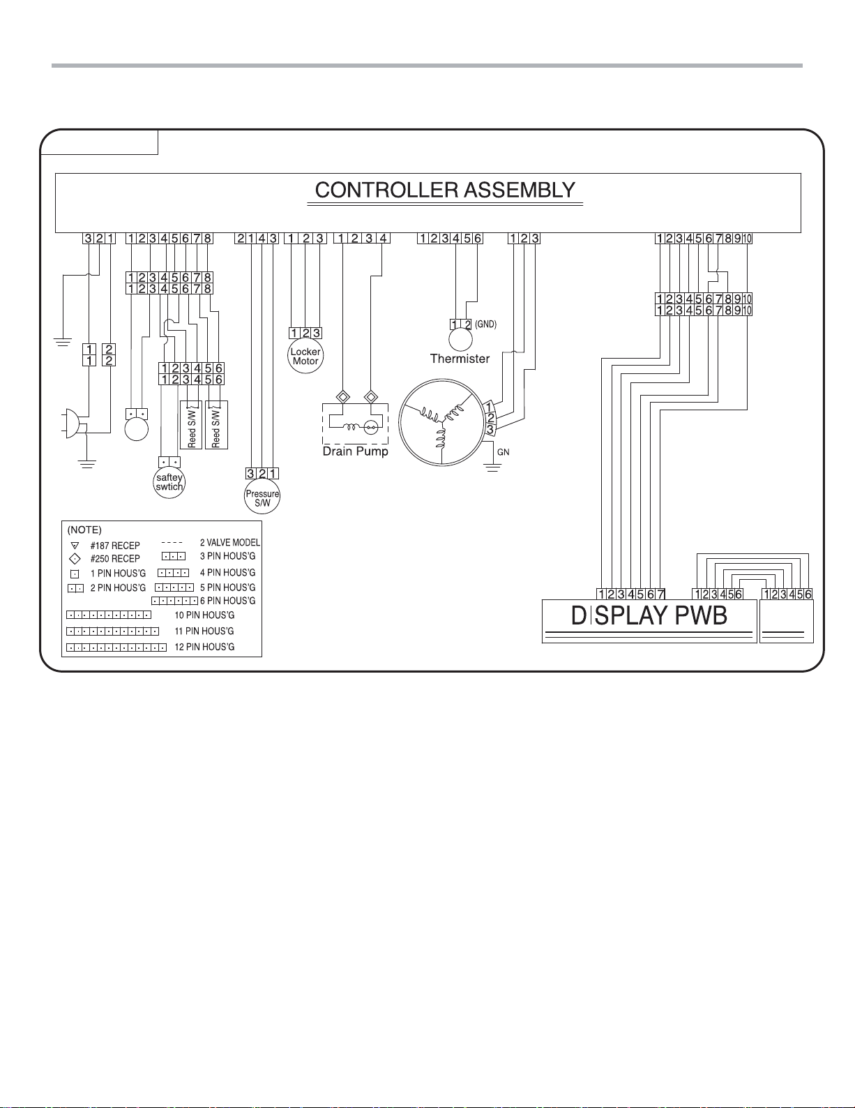
4. WIRING DIAGRAM .................................................................................................................... 6
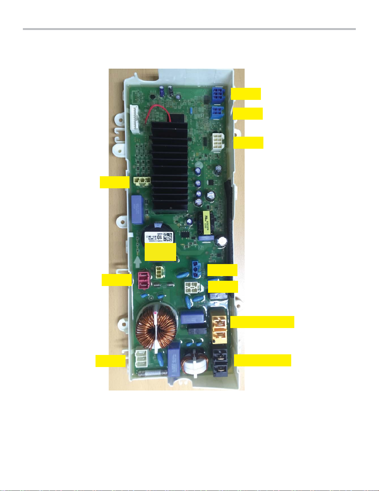
5. MAIN PCB PICTURE ................................................................................................................. 7
6. SERVICE INFORMATION ......................................................................................................... 8
7. HOW TO USE SVC TEST MODE .............................................................................................19
8. ERROR CODES......................................................................................................................... 20
9. EXPLODED VIEW........................................................................................................................... 22
9-1. EXPLODED VIEW OF OUTER CASE ASSEMBLY .......................................................... 22
9-2. EXPLODED VIEW OF FRONT COVER ASSEMBLY ....................................................... 23
9-3. EXPLODED VIEW OF DRAWER ASSEMBLY ................................................................. 24
9-4. EXPLODED VIEW OF TUB ASSEMBLY ......................................................................... 25
9-5. EXPLODED VIEW OF ACC. ASSEMBLY...........................................................................26
SAFETY PRECAUTION!

3
ledoM
zH05/V042-022CAlacirtcelE
sselniatSbuTrennI
Finish
W : Blue White V : Stainless Silver(VCM)
Door lid
Plastic Lid.
Inlet Water Pressure
30~800 kPa
zH05/V042-022esuFfognitaR
)xaM(MPR007deepSnipS
gk34thgieW
Cycles
Light Soil, Speed Wash, Active Wear, Hand Wash,
Rinse+Spin, Spin Only, Tub Clean
oNyaleDemiT
Lid Interlock Switch
Magnet Sensor
seYkcoLlortnoC
Softener Dispenser
No
Detergent Dispenser
No
oNtelnIhcaelB
seY
seY
Smart Rinse™with Jet
Spray
No
retaeH
1. SPECIFICATIONS
WTP20BK
Wi-Fi Module

4
INSTALLATION EN
Parts
7
8
6
5
4
3
2
1
Door
Drum
Control Panel
Drawer
1
2
3
4
Water Supply Hose
Power Plug
Water Drain Hose
Leveling Feet
5
6
7
8
Accessories
Water supply hose
(for cold water)
Connecting
supply hose
Water drain hose Water supply hose
connector
Water drain hose
connector
Anti-slip sheets
(2 EA)
Detergent
measuring
cup
Brackets (front)
(2 EA)
Brackets (back)
(2 EA)
Spanner
* Screws
Type A (37 EA)
Type B (5 EA)
Type C (3 EA)
Cable ties
(2 EA)
Band clamps
(3 EA)
Stacking holder Remote control
(optional)
* Type A : long sheet metal screw, Type B : short sheet metal screw, Type C : machine screw
NOTE
•Different accessories may apply to each model.
•The stacking holder is for preventing independent operation.
•Depending on the installation environment, you may have to purchase a separate drain hose
connector.
•In addition to the screws required for installation, extra screws have been provided.

5
EN
Control Panel
Power Button
•Press the Power button to turn the
washing machine on.
Display
•The display shows the cycle status and
estimated time remaining.
•: Drawer lock indicator
•: Wi-Fi connect indicator
•: Remote start indicator
Programme Button
•Programmes are available according to
laundry type.
•In order to use the Download Cycle
function, refer to SMART FUNCTIONS.
1
2
3
Start/Pause Button
•This Start/Pause button is used to start the
wash cycle or pause the wash cycle.
•If a temporary stop of the wash cycle is
needed, press the Start/Pause button.
NOTE
•If you do not press the Start/Pause
button within 15 minutes of selecting
a programme, the washing machine
automatically turns off and all cycle settings
are lost.
Options
•Use these buttons to select the desired
options for the selected programme.
•The setting lights above the buttons
illuminate to show the current selection.
4
5
1
2
4
5
3

6
Cold
Valve
Base / Line
WH
NA
WH
BN BL
BL
GN/YL
GN/YL
BN BK BL BL
BLBL
BL BLBL
BK
BK
OR
OR
OR
YL
YL
WH BL
BL
WH
WH
WHWH
WH
BK
BN
BN
RD
RD
OR
OR
YL BL
BL
VT
VT
GY
GY
YL
WH
WH
WH WH
WH
WH
BL YL NA
BL BL
WIRING DIAGRAM
4. WIRING DIAGRAM
wi-Fi
BKVT SB BL WH BK BK BN
WH
WH YL RD BL YL

7
&1
YL3
RD2
WH1
BL6
BL4
WH8
WH2
BL3
X1_YELLOW
X2_BLACK
5. MAIN PCB PICTURE

8
Be sure to unplug the power to repair and replace
electric parts.
ESD (ElectroStatic DIscharge) WARNING
Be sure to follow proper ESD and grounding
precautions for diagnosis and repair. If this is not
possible, touch the ground wire on a regular basis to
remove any static charge built up on your person.
6. SERVICE INFORMATION
1) Change the display assembly parts
①Open the drawer and unscrew the 4 fixing screws at the
left and right sides of the front panel.
②Pull the unlock ring of the drawer at the bottom of the
front panel.
③Pull the front panel and remove the controller connector.
Then, lift the front panel to remove it.
④Release 11 screws on the front panel around.
⑤Remove the inner panel and pull the top portion fixed
with a hook completely while holding the front panel.
⑥Release display PCB and Wi-Fi Module module,

9
2) How to release the rear cover, the Power
cord, and the main controller
①Release all screws on the rear cover
②Pull out 2 connectors and release the power cord
③Release 3 screws on the cover of main controller and
pull out the cover
④Release all connectors on the main controlloer
⑤Release 4 screws on the main controller and pull out the
main controller

10
OjGPG OpGP
⑥Tuck the harness core into the drawer rib to fix it in
place.
⑦Assemble the main PCB and drawer connecting
screw
⑧Secure the main PCB in place with 3 screws.
⑨ Assemble the rear cover

11
3) How to release the drawer assembly
①Release the rear cover totally from the cabinet
②Release 1 screw and 1 connector on the rear cover
③Open the drawer and release 4 screws securing the
slider and the rawer on the both sides.
④Pull out the drawer entirely from the cabinet

12
4) How to change the suspension assembly
①gnillupretfarewardehtnorevocllamsehtesaeleR
out the drawer.
②ehttuollupdna,pmalc1dnaswercs7esaeleR
cover of drawer.
③potehthcatedotylthgilsylbmessabutehttfiL
portion and then remove the bottom portion.
In this way, remove all four suspensions.
④.eromnwodylbmessanoisnepsusehtkaerbtonoD
Change the suspension assembly as a whole.

13
5) How to change the motor assembly
①Pull out the drawer entirely
②In order to check the rotor assembly, turn the drawer
to be the side up. Be sure the drawer keeping on the
securing carpet to be protected from the damage.
③Release the motor bolt using dedicated tool.
▶Use the socket wrench or the open wrench (M17).
* Bolt torque when ressembl : 450~600kgf·cm
2
④Pull out 3 pin connector and release the motor stator.
⑤First, unscrew the stator bolts at the bottom of the
product. Unscrew the bolt at the top tastly.
At this time, the stator my fall when you unscrew the top
bolt, so make sure that you hold the stator with on hand
when unscrewing the top bolt.
⑥When you ressemble the stator, the wire may stacken
due to the vibration and touch the roter, posing a risk of
disconnection. So make sure that the wiring is property
arranged when you ressemble the stator.

14
6) How to release the inner tub
①Pull the drawer to completely remove the rotor.
②After putting the drawer back to its proper position,
completely remove the drawer cover.
③Loosen the 8 screws on top of the tub assembly.
④Release the tub cover.
⑤Release the inner tub.

15
7) How to pull out the drain pump
①Drain the whole remaing water out using extra drain
hose on the left-side of drawer.
②Pull out the drawer entirely.
③Turn the drawer to be the side up. Be sure the drawer
keeping on the securing carpet to be protected from the
damper.
④Release the bellows connected on the out tub.
⑤Turn the drawer to be normal position and release 2
connectors on the pump case.
⑥Release 3 hoses from pump housing.

16
7-1) How to Remove the Remaining Water
Hose and Siphon Hose
①Remove the drawer completely and then remove the
drawer cover.
②
7) Refer to "How to Remove the Water Drain Pump" to
remove the pump.
③Remove the Remaining Water Hose at the bottom left of
the tub assembly.
④Remove the holder that holds the siphon hose on the
back of the drawer.
⑤Remove the hose connected to the pump housing and
then remove the hose connected to the tub assembly.

17
8) How to release the heater
①Drain the whole remaning water out using extra drain
hose on the left-side of drawer.
② Pull out the drawer entirely.
③Place the product sideways and unscrew the three
screws from the heater cover the bottom of the outer tub.
(Make sure that you place the protective cloth at the door
before you place the product sideways to prevent the
drawer or front panel from being damaged.)
④Remove the three housings from the heater and use a
box wrench (M10) or other wrench to loosen the screws
sufciently and pull the heater to remove it.

18
9) How to pull out the pipe assembly
①Drain the whole remaning water out using extra drain
hose on the left-side of drawer.
② Pull out the drawer entirely.
③Release the small cover on the drawer, 3 screws and the
clamp.
④Release 4 clamps connected on the pipe assembly and
2 pins.
⑤Release the check valve from the end of pipe assembly.

19
XUG~
jGGGGGGhjGYYW}GGkjGUGiGGGGG
GGGU
iGGGGhjGGGGGGGGU
wGGGGGGGGGGGU
kGGGGGGGlzkGGU
U
YUGz}jGG
zGz}jGGaGhGGSGGsGjGGGlGyGGGGGGGXU
wGzVwGGGGGU
GGGGGGGGGGU
z t t k y
X tG}G
G hGslkGGG
TUGtGGGGa
aGGˈthpuG}lyz{pvuˉGGˈtG
GGGˉ
TGtGGGGGa
aGGˈthpuG}lyz{pvuˉGSˈtGGˉ
GGˈxGGzVjsˈ
hGGGlGU
Y
kG}G
GGiG
{GkGsVjGsGpG
GGGGOWU\GPSG
GGOWU\GPSGwGslkSG
GGGzG
GGOWU\PUG
G
kGymGtGwntGUGGY
OYTeffOG}UPTemffOymG}UPP
QOsxjSGz}jGGGP
T
Z ~G}G
jGG ~GG
O\^GGY\U^Gro¡P
}GGGGGYZUZGro¡
}GGGG
GYZUZGro¡GGG
G
G
[ oG oG hG\GGGGUTGkG
TGoGU
\
wGz
hG
hGGGG
UGkGG
GGU
hGywt
ywtaGYYW
vGaGX]G
wG
] kG vGGGG
GGY\U`Gro¡SGG
GGGGG
\WGU
hGSGGGG^
U
wG
^ sGG
rGGGGGG_U
wG
_
zGG
G
l^GG
sGGGz
zGywtGsGG\WWGaGGywtG
nGG\WWGaG|iGVGtG|iG
GG\WWGywtGVG|iGGGyzXV
jGywtGOGGYGP
yGU
tGywtGaG]WWywt
wG
` vmm wG
7. HOW TO USE SVC TEST MODE

20
8. Troubleshooting and Measures
Display Problem Possible Cause Solution
water inlet
error
( Water fills
with water
slowly or
not at all)
●There is no change in the
10 Hz water level for three
minutes after starting to
supply water.
●
There is no change in the
water level frequency for 10
minutes
●
The water level does not
reach the washing or rinsing
level for 25 minutes after
starting to supply water.
1. Water supply faucets are not fully
open.
2. Water line hoses are kinked, pinched,
or crushed.
3. Water inlet filters are clogged.
4. Water supply connected with
leaklimiting hoses.
5. The red 6-pin connector connected to
the controller is not properly connected
or has a faulty connection.
6. The controller's load driving section
has an error.
7. The pressure switch has an error.
•Make sure that the water
faucets are fully open.
•Perform washing after making
sure that the water is supplied
properly.
•Clean the inlet filters. See
maintenance in the care and
cleaning section.
•Reconnector or repair the
connector
•Change the controller
•Check the pressure switch
water
outlet error
(Water in
the washer
drains
slowly, or
not at all)
●
The water level frequency
does not reach the RESER
water level frequency (26.0
kHz) for 12 minutes after
starting to drain the water.
●
Too much detergent bubbles
remain inside the inner tub.
1. The drain hose is not lowered.
2. Drain hose is kinked, pinched or
clogged
3. The connector connected to the drain
pump or the blue 3-pin connector
connected to the controller is not
properly connected or has a faulty
connection.
4. The drain pump is faulty. (The pump
does not operate even when a
separate AC 220V power is connected
to the 3-pin terminal of the drain
pump.)
5. Controller Asem have some problem.
6.
Remove the detergent bubbles from
the clothes and tub.
• Make sure the drain hose is
free of clogs, kinks, etc, and is
not pinched behind or under
the washer
• Reconnect or repair the
connector
• Change the drain motor
• Change the controller
Unbalance
error
Not
operated
to drain
● The load is out of balance.
1. The laundry is not evenly distributed
but skewed to one side inside the
inner tub assembly.
2. The washing machine is inclined.
• Make sure that the laundry is
evenly distributed inside the
tub.
• Adjust the legs so that the
washing machine is level.
Thermistor
(heating)
error
Thermistor
fails.
●
Water fills with water slowly
or not at all
1. The blue 6-pin connector of PCBA,
thermistor, or connector connection is
faulty.
2. The connection between PCB and
thermistor is faulty or damaged.
• Reconnect or repair the
connector
• Reconnect or repair the
connected part
Pressure
sensor
S/W error
Pressure
sensor has
a problem.
●
The frequency generated
by the pressure switch that
determines the water level
exceeds the standard range.
(Water level frequency is
less than 20.0 KHz or more
than 30.0 KHz for 5 seconds
or more.)
1. The connector connected to the
pressure switch or the blue 6-pin
connector connected to the controller
is not properly connected or has a
faulty connection.
2. Pressuer switch is poor
3. Controller is poor
•Make sure that the water
faucets are fully open.
•Perform washing after making
sure that the water is supplied
properly.
•Clean the inlet filters. See
maintenance in the care and
cleaning section.
•Reconnect or repair the
connector
•change the controller
•check the pressure switch
Table of contents
Other LG Washer manuals