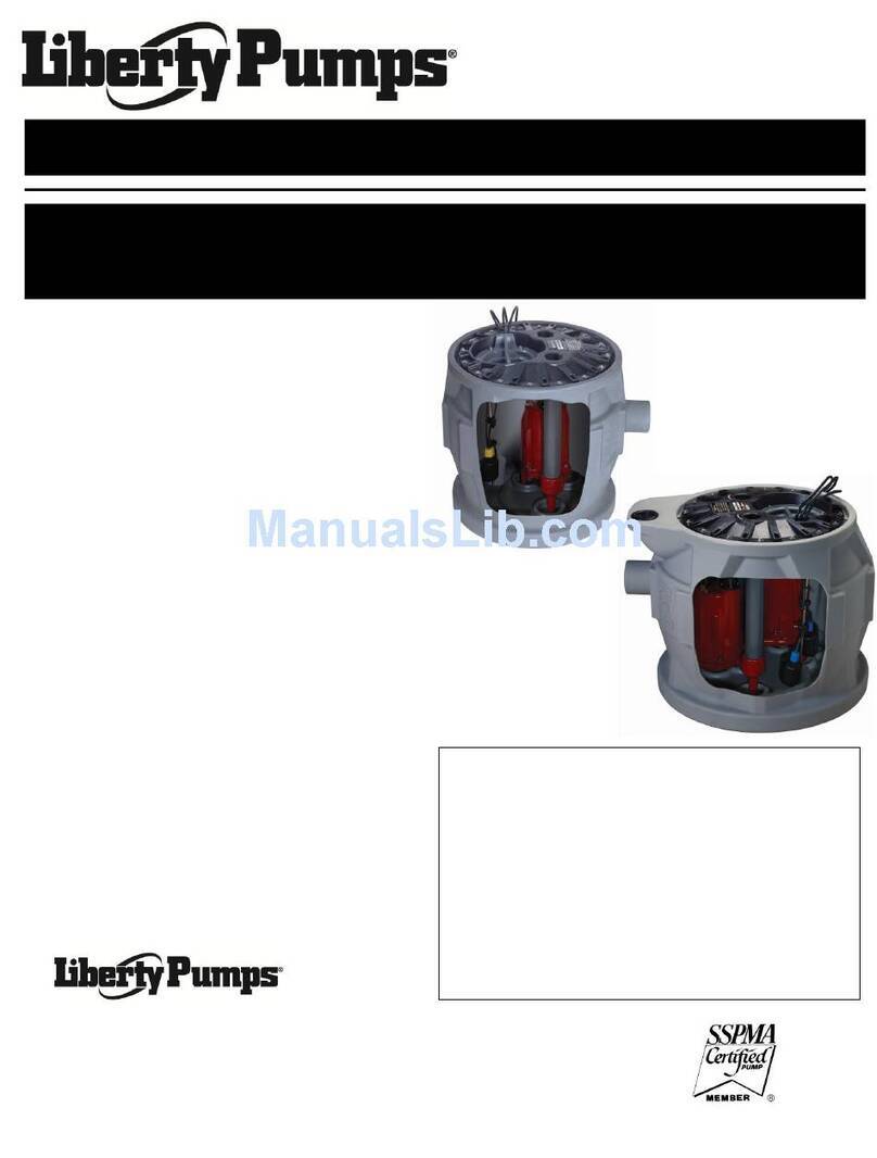
Liberty Omnivore SERIES User manual

©Copyright 2012 Liberty Pumps Inc. All rights reserved
Models:
LSG202A
2 hp, 208/230V, 1 phase, Automatic
LSG202M
2 hp, 208/230V, 1 phase, Manual
LSG202M-C
2 hp, 208/230V, 1 phase, Manual, external caps
LSG203M
2 hp, 208/230V, 3 phase, Manual
LSG204M
2 hp, 440-480V, 3 phase, Manual
LSG205M
2 hp, 575V, 3 phase, Manual
LSGX202A
2 hp, 2-Stage, 208-230V, 1 phase, Automatic
LSGX202M
2 hp, 2-Stage, 208-230V, 1 phase, Manual
LSGX202M-C
2 hp, 2-Stage, 208-230V, 1 phase, Manual, external caps
LSGX203M
2 hp, 2-Stage, 208/230V, 3 phase, Manual
LSGX204M
2 hp, 2-Stage, 440-480V, 3 phase, Manual
LSGX205M
2 hp, 2-Stage, 575V, 3 phase, Manual
*Do not throw away or lose this manual.
Contents
General Information
Introduction
Mechanical Installation
Electrical Connection
Operation
Warranty
Installation Manual 5647000I
Omnivore® Sewage and Grinder Pumps
IMPORTANT:
Prior to installation, record Model, Serial
Number, and Code Number from pump
nameplate for future reference.
MODEL _____________________
SERIAL _____________________
CODE _____________________
INSTALLATION
DATE _____________________
7000 Apple Tree Avenue
Bergen, NY 14416
Phone: (800) 543-2550
Fax: (585) 494-1839
www.libertypumps.com

©Copyright 2012 Liberty Pumps Inc. All rights reserved - 2 -
SECTION 1 GENERAL INFORMATION------------------------------------------------------------------------------ 3
SECTION 2 INTRODUCTION-------------------------------------------------------------------------------------------- 4
SECTION 3 MECHANICAL INSTALLATION ----------------------------------------------------------------------- 4-6
SECTION 4 ELECTRICAL CONNECTION-------------------------------------------------------------------------- 6-8
SECTION 5 OPERATION ------------------------------------------------------------------------------------------------ 9
TROUBLESHOOTING CHART ------------------------------------------------------------------------ 10
PANEL INSTALLATION SHEET----------------------------------------------------------------------- 11
TYPICAL INSTALLATION DRAWING-----------------------------------------------------------------12
PERFORMANCE CURVE------------------------------------------------------------------------------- 13
SECTION 6 WARRANTY------------------------------------------------------------------------------------------------- 14
Table of Contents

©Copyright 2012 Liberty Pumps Inc. All rights reserved - 3 -
1.
Before installation, read the following instructions carefully. Each Liberty pump is individually factory tested to insure proper
performance. Closely following these instructions will eliminate potential operating problems, assuring years of trouble-free service.
Risk of electric shock. Always disconnect the pump from the power source before handling or making adjustments.
The electrical connections and wiring for a pump installation should only be made by qualified personnel.
This pump is supplied with a grounding conductor and grounding-type attachment plug. To reduce the risk of electric
shock, be certain that it is connected only to a properly grounded, grounding-type receptacle.
DO NOT bypass grounding wires or remove ground prong from attachment plugs.
DO NOT use an extension cord.
This pump requires a separate, properly fused and grounded branch circuit. Make sure the power source is properly
sized for the voltage and amperage requirements of the pump, as noted on the nameplate.
The electrical outlet shall be within the length limitations of the pump power cord, and at least 4 feet above floor level
to minimize possible hazards from flood conditions.
The installation must be in accordance with the National Electric Code, Uniform Plumbing Code, International
Plumbing Code, as well as all applicable local codes and ordinances.
Sump and sewage pumps often handle materials which could cause illness or disease. Wear adequate protective
clothing when working on a used pump or piping.
Never enter a pump basin after it has been used. Sewage and effluent can emit several gases which are poisonous.
Keep clear of suction and discharge openings. To prevent injury, never insert fingers into pump while it is plugged in.
DO NOT use this product for flammable or corrosive liquid.
DO NOT use this product in applications where human contact with the pumped fluid is common (such as swimming
pools, fountains, etc.)
NEVER dispose of materials such as paint thinner or other chemicals down drains, as they can chemically attack and
damage pump components, potentially causing product malfunction or failure.
Do not use these pumps in water over 140 F.
The Uniform Plumbing Code (UPC) states that sewage systems shall have an audio and visual alarm that signals a
malfunction of the system, to reduce the potential for property damage.
Note: Manual models (“M”
suffix), require a separate
approved pump control device or
panel for automatic operation.
Operation of these models will be
according to the control selected.
Make sure the electrical
specifications of the control
selected properly match the
electrical specifications of the
pump. Always refer to control
panel instructions for proper
installation.
Models with ("M-C" suffix) require
external capacitors and relay.
(Order kit K001316)
start cap - 200-240, 220V
or 216 – 259 uf, 250V
run cap - 50 uf, 370V
Mars Potential Relay 19551 (#551)
pick up 244V – 270V
drop out of 40V-90V
Model
HP
Volts
Pha
se
Full Load
Amps
FNPT
Discharge
Automatic or
Manual*
LSG202A
2
208/230
1
15
1.25”
Automatic
LSG202M
2
208/230
1
15
1.25”
Manual
LSG202M-C
2
208/230
1
15
1.25”
Manual
LSG203M
2
208/230
3
10.6
1.25”
Manual
LSG204M
2
440-480
3
5.3
1.25”
Manual
LSG205M
2
575
3
4.9
1.25”
Manual
LSGX202A
2
208-230
1
15
1.25”
Automatic
LSGX202M
2
208-230
1
15
1.25”
Manual
LSGX202M-C
2
208-230
1
15
1.25”
Manual
LSGX203M
2
208/230
3
10.6
1.25”
Manual
LSGX204M
2
440-480
3
5.3
1.25”
Manual
LSGX205M
2
575
3
4.9
1.25”
Manual
General Information

©Copyright 2012 Liberty Pumps Inc. All rights reserved - 4 -
2.
2-1 INTRODUCTION
This manual was prepared to assist you in the correct installation, operation, and maintenance of your Liberty
pump. Please read it completely before installing the pump. Make certain that you are familiar with the contents,
and the chapters on installation and operation are fully understood before running the pump.
Liberty Pumps are designed for minimal maintenance. However, regular checks will ensure longer life and
greater operating reliability.
WARRANTY: No repair work should be carried out during the warranty period without prior factory approval. To
do so may render the warranty void.
SERIAL #: In all correspondence and reports, make certain that the pump serial number is given.
2-2.1 DESIGN OF PUMP
The grinder pump contains metal parts that rotate at high speeds. Be careful around
pump base while power is connected. Make sure that the pump is either in the tank or
clear from people and wires when in operation.
1. Liberty LSG and LSGX-Series grinder pumps are designed for continuous underwater operation. The motor and
pump form a close coupled, watertight unit. The induction motor is insulated against heat and moisture in
accordance with Class B 265F (130C) regulations.
2. A thermal overload protector is imbedded in the stator windings. This is connected in series and wired to shut
down the pump if overheating occurs. The overload switch resets automatically when the motor cools.
3. The motor is protected against damage from water entry by two seals. The lower seal is a Viton lip seal. The
upper seal is mechanical, consisting of two silicon-carbide faces.
4. The impeller and volute are designed for efficient flow characteristics and clog-free operation. The hardened
cutters grind solids and fibrous matter into small particles that can be safely pumped through small diameter
piping.
5. For sewage systems, consult local plumbing codes on requirements of venting the tank. The pump shall not be
installed in locations classified as hazardous in accordance with the National Electrical Code, ANSI/ NFPA70.
NOTE: The major material of Liberty LSG and LSGX-Series pumps is cast iron. They should not be used to pump
corrosive liquids.
3.
3-1 INSPECTION UPON RECEIPT
The shipping container should be immediately inspected for damage that may have occurred in shipment.
Exercise care in opening the shipping container to avoid damage to the pump. Remove any blocking and
cushioning from within the container.
Check all cushioning for spare parts before discarding. Visually check the pump and any spare parts for damage.
Check for damaged electrical wires, especially where they exit the motor housing. Contact the Liberty Pumps
Customer Service Department to report any damage or shortage of parts. Turn the hex socket head cap screw at
the center of the cutter wheel on the bottom of the grinder several rotations clockwise. This will insure that the
impeller and cutter are free of any seizure due to prolonged storage. If the impeller is not rotated manually prior
to installation, the pump may fail to activate. If the impeller’s rotation is difficult or completely resistant, contact
the Liberty Pumps Customer Service Department.
Introduction
Mechanical Installation

©Copyright 2012 Liberty Pumps Inc. All rights reserved - 5 -
3-2 STORAGE BEFORE USE
Liberty pumps are shipped from the factory ready for installation and use. They should be held in storage if the
pump station is not complete. If storage is necessary, the pump should remain in its shipping container. It should
be stored in a warehouse or storage shed that has a clean, dry temperature-stable area where the pump and its
container should be covered to protect it from water, dirt, dust, etc. The ends of the cables - (plugs) must be
protected against moisture.
AT NO TIME SHOULD THE PUMP BE STORED WITHIN AN INCOMPLETE WET PIT. THE PUMP
SHOULD NOT BE PLACED INTO THE PIT UNTIL IT CAN BE FULLY OPERATED.
LONG TERM STORAGE
1. If it is necessary to store a pump for a long period of time, it should be stored indoors in a clean, dry temperature-
stable environment. The pump should be covered to protect it from dust, dirt and water. The plug end of the
cable must be protected against moisture.
2. Do not allow the pump to freeze.
3. Prior to installation, the pump motor should be rotated to ensure the seals and cutters are free spinning.
4. Installed pumps which are idle for long periods of time should be manually operated through the breaker panel
once a month to lubricate the seals. Turn off the breaker, unplug the piggyback switch, and plug the pump
directly into the wall socket. Turn the breaker on for 30 seconds. Turn the breaker off, and then plug the
piggyback switch back in. (refer to Section 4-1)
3-3 PUMP INSTALLATION
THIS PUMP IS NOT TO BE INSTALLED IN LOCATIONS CLASSIFIED AS HAZARDOUS IN
ACCORDANCE WITH THE NATIONAL ELECTRICAL CODE,ANSI/NFPA 70.
Grinder pumps must be installed in a tank that is vented in accordance with local plumbing codes.
Installation should be at a sufficient depth to ensure that all plumbing is below the frost line. If this is not feasible,
remove the check valve and size the basin and/or adjust pump differential to accommodate the additional
backflow volume. Consult the factory for details on how this should be done.
The Omnivore Grinders may be guide rail mounted using Liberty's GR20 guide rail base, or stand-alone. (See
Figure 3, page 11) They may be installed as a completely packaged simplex (single pump) or duplex (two-pump)
system. Installation of the pump shall be in accordance with state and local codes and performed only by
qualified personnel. Typical installations consist of a guide rail mount in a fiberglass, concrete or polyethylene
tank. This section assumes guide rail installation.
NEVER LIFT THE PUMP BY PULLING ON THE POWER CORD.
USE THE LIFTING CHAIN OR CABLE ONLY
1. Liberty GR20 Guide Rail systems feature a self-aligning mounting bracket. Using the lifting chain, slip the pump
bracket over the upper guide rail bracket. Lower the pump at an angle down the guide rail into the tank. (See
Figure 3, page 11)
2. As the pump nears its final position, the straightening rib squares the pump bracket with the guide bracket ears.
When the pump bracket ears hook the guide bracket ears, the chain will slacken.
3. Grasp the lifting chain and shake the pump to ensure a good seat with the gasket. The pump is suspended by
the bracket ears. The weight of the pump compresses the gasket against the mating flange of the guide bracket
base.
4. The lifting chain may be removed from the hoist and hooked near the upper guide rail bracket.

©Copyright 2012 Liberty Pumps Inc. All rights reserved - 6 -
IMPORTANT: For 3-phase pumps, check for proper rotation before installing pump into basin. See figure A for proper
rotation.
4.
AFTER THE PUMP IS INSTALLED, THE ELECTRICAL CHECKS OF SECTION 4 MUST BE PERFORMED.
4-1 PIGGY BACK SWITCH OPERATION
1. Plug the Piggyback switch into a 6-20R receptacle. The receptacle must be
wired to a 30-amp breaker. Be sure to have the breaker turned off before
plugging in the switch.
2. Plug the pump power cord into the piggyback switch as shown.
3. The pump is ready to test and your breaker can be turned on.
(Refer to section 5)
ALWAYS TURN OFF BREAKERS BEFORE
WORKING ON ELECTRICAL CORDS.
BE CAREFUL NOT TO DRILL OR SCREW INTO
EXISTING WIRING.
Check to make sure installation is in accordance
with the National Electric Code and all applicable local codes. Installation and servicing is to be
conducted by qualified personnel. This pump is supplied with a grounding conductor. To reduce
the risk of electrical shock, be certain that it is connected to a properly grounded earth wire.
4-2 DIRECT WIRING OF AUTOMATIC PUMP
The pump can run on a voltage rating of
230V or 208V. Check that it is the same as
the supply voltage. The pumps are
supplied with 6-20P (20-amp) cord plug
ends. If a single phase pump is to be wired
directly into a control device or junction box,
and it is necessary to remove the plugs,
have a certified electrician do the wiring in
accordance with the National Electric Code
and applicable local codes. See Fig. B for
direct wire installation of single phase,
automatic pumps.
1. The control panel is preferably mounted
in a cool, dry environment. Installation
and connections are specific to the
control panel. Control panels should be
installed and serviced only by a
qualified electrician (Refer to Figure 2, page 10).
Electrical Connection
Bottom
View
Fig. A – Proper impeller
rotation, three phase models
Check three phase pumps for proper
rotation prior to installing pump(s) in
basin. To change rotation, reverse any
two of the three power leads to the
pump. Code the wires for reconnection
after installation.
Fig. B – Direct Wiring of 120V or 208-
230V Single Phase, Automatic Pumps

©Copyright 2012 Liberty Pumps Inc. All rights reserved - 7 -
4-3 CONTROL PANEL OPERATION
REFER TO WIRING DIAGRAM INCLUDED WITH CONTROL PANEL. IF THERE IS NO WIRING
DIAGRAM, CONTACT THE MANUFACTURER TO OBTAIN ONE. DO NOT ATTEMPT TO
CONNECT PUMP WITHOUT A WIRING DIAGRAM.
4-4 EXTERNAL CAPACITORS
The LSG202M-C and LSGX202M-C (208-230V SINGLE PHASE UNITS) are designed such that the capacitors and start
relay are mounted in a control panel external from the pump. The most basic wiring diagram is illustrated in Figure C.
Increased functionality of the panel like simplex or duplex pump control would complicate the wire schematic. Before
connecting the pump consult the schematic for the specific panel or contact the panel manufacturer.
Figure C
4-5 STEPS TO BE TAKEN BEFORE ENERGIZING
1. Retighten all field-made connections. Retighten all factory-made connections. These may have loosened due to shipping and
handling vibrations.
2. Check the security of mounting hardware.
3. Check the enclosure to see that it has not been damaged in such a manner as to reduce electrical spacing.
4. Rotate the cutter wheel with the hex socket head cap screw to verify movement and lubricate the seals.
5. Ensure that no wires or other obstacles are in the way of the pump cutter.
6. Conduct an electrical insulation resistance test to make sure that the control panel is free from short circuits and ground faults.
This should be done both phase-to-phase and phase-to-ground.
7. MOTOR OVERLOAD PROTECTION: The pump motor is protected from locked rotor and running overloads by a thermal
overload integrally mounted to the motor (Single Phase Only). No adjustments are required.
8. Check to determine that all grounding connections are made properly
9. If a panel is used, remove all debris, scrap wire, etc., from the control panel interior before closing the doors. Install covers,
close doors making certain that no wires are pinched and that all enclosure parts are properly aligned and tightened.
ENERGIZING THE CONTROL PANEL OR BREAKER FOR THE FIRST TIME IS POTENTIALLY
DANGEROUS. LICENSED ELECTRICAL PERSONNEL SHOULD BE PRESENT WHEN THE PANEL
OR BREAKER IS ENERGIZED FOR THE FIRST TIME. IF FAULTS CAUSED BY DAMAGE OR POOR
INSTALLATION PRACTICES HAVE NOT BEEN DETECTED, SERIOUS DAMAGE CAN RESULT
WHEN POWER IS APPLIED (REFER TO SECTION 5).
4-6 FLOAT SWITCHES
1. The pump's on and off cycles are normally controlled by a "piggy back" float switch attached to the side of the pump, or by
hanging switches in the wet well. Refer to panel or switch instructions for proper electrical connection
Component specifications:
start cap - 200-240 uf, 220V
or 216 – 259 uf, 250V
run cap - 50 uf, 370V
Mars Potential Relay 19551 (#551)
pick up 244V – 270V
drop out of 40-90V
(Available in Start Kit K001316)

©Copyright 2012 Liberty Pumps Inc. All rights reserved - 8 -
4-6.1 FLOAT SEQUENCE- PIGGY BACK (AUTOMATIC MODELS LSG202A & LSGX202A)
1. As the liquid level in the wet well rises, the float tilts, closing the switch. This starts the pump.
2. The pump runs until the liquid level falls below the “PUMP OFF” level of the float (Factory set at 7" minimum), emptying the
wet well.
4-6.2 FLOAT SEQUENCE- SIMPLEX (MANUAL MODELS)
1. As the liquid level in the wet well rises, the “PUMP OFF” float tilts, closing the switch (This level must be set at a minimum of
7"). As the liquid level continues to rise, the “PUMP ON” float tilts. This switch closes, starting the pump.
2. The pump runs until the liquid level falls below the “PUMP OFF” float, emptying the wet well.
3. In the event of a malfunctioning float switch, control relay or pump, the liquid level rises and tilts the “HIGH LEVEL ALARM”
float. The alarm system will activate.
4-6.3 FLOAT SEQUENCE-DUPLEX (MANUAL MODELS)
1. As the liquid level in the wet well rises, the “PUMP OFF” tilts, closing the switch. As the liquid level continues to
rise, the “LEAD PUMP ON” float tilts. This switch closes, starting the lead pump. The pump runs until the liquid
level falls below the “PUMP OFF” float, emptying the wet well.
2. On the next rise of the liquid level, the other pump will start on the “LEAD PUMP ON” signal. The pumps will
continue to alternate their cycles.
NOTE: The ON/OFF float switch differential should be set as to not exceed 12 starts per hour.
3. If the liquid level rises to the “LAG PUMP ON" float, the second pump will start. Both pumps will run until the
liquid falls below the “PUMP OFF” float, emptying the wet well.
4. In the event of a malfunctioning float switch, control relay or pump, the liquid level rises and tilts the “HIGH LEVEL
ALARM” float. The alarm system will activate.
4-6.4 FLOAT SWITCH INSTALLATION
The engineering drawings will normally specify the levels for pump start and stop and high level alarm. If they are not
specified, these guidelines should be used to determine float switch locations.
PIGGY BACK SWITCH
(1-Float System)
Pump Off: Factory set. (Float tether 4")
Pump On: Factory set. (Float tether 4")
SIMPLEX PUMP STATION
(3-Float System)
Pump Off: Level to top of motor housing.
Pump On: Minimum 1-1/2 ft. above Pump Off Level.
High Level Alarm: Minimum 1 ft. above pump ON level. Below influent pipe.
DUPLEX PUMP STATION
(4-Float System)
Pump Off: Level to top of motor housing.
Lead Pump On: Minimum 1-1/2 ft. above Pump Off level.
Lag Pump On: Minimum 1 ft. above Lead Pump On level.
High Level Alarm: Minimum 1 ft. above Lag Pump On level. Below influent pipe.

©Copyright 2012 Liberty Pumps Inc. All rights reserved - 9 -
5.
5-1 OPERATION
After the electrical and mechanical installations have been performed, the pump is ready for operation. No operational
procedures are required except to apply rated power to the pump. There are no specific shutdown procedures beyond
disconnecting the power supply.
IF THE ROTATION OF A SINGLE PHASE PUMP IS INCORRECT, NOTIFY THE LIBERTY PRODUCT
SERVICE DEPARTMENT IMMEDIATELY. DO NOT SWITCH THE POWER SUPPLY LEADS. DO NOT
OPERATE THE PUMP.
ALWAYS ENSURE THAT THE PUMP IS FREE OF WIRES OR OTHER OBSTRUCTIONS THAT MAY CAUSE
HARM OR INJURY.
5-2 PERIODIC MAINTENANCE & LUBRICATION
Liberty pumps are designed for long lasting, efficient and reliable service with a minimum of preventive maintenance checks.
These checks are few but will add years of satisfactory service to the life of the pump. Maintenance checks should be
performed at the intervals stated. Severe operating environments will require more frequent checks.
5-3 LUBRICATION
Pump is permanently lubricated and cooled by turbine oil. If replacement oil is required, use ISO-32 turbine oil. If this is
unavailable a full synthetic SAE 5W-30 or 5W-20 motor oil may be used. Capacity .8 gallons.
5
.
Operation
Operation

©Copyright 2012 Liberty Pumps Inc. All rights reserved - 10 -
TROUBLESHOOTING CHART: LSG200
SYMPTOM
1. PUMP WILL NOT START
2. REPEATED TRIPPING
3. PUMP WILL NOT SHUT
OFF
4. LOW FLOW
5. WATER IN OIL CHAMBER
6. WATER INSIDE MOTOR
CASING
POSSIBLE CAUSE
A. Power supply failure
B. Burned out fuse or tripped circuit
breaker
C. Damaged power cable
D. Jammed impeller
E. Water inside motor
A. Circuit protection under-rated
B. Current unbalance
C. Pump connected to incorrect
voltage
D. Wet or damaged wiring
E. Obstruction in pump
F. Incorrect motor rotation
G. Foreign matter build-up
A. Control panel failure
B. Switch Failure
A. Incorrect pump rotation
B. Low liquid level
C. Obstruction in pump or piping
D. Partially closed valve(s)
A. Loose or damaged oil plug
A. Damaged lower lip seal or
mechanical seal
B. Damaged O-Ring between oil
chamber and motor plate
C. Damaged cable
ACTION
A. Check power supply
Check out electrical system for
loose connections
Check operating voltage
B. Check circuit protectors
C. Check external cable for damage
– repair
D. Inspect and remove jamming
object
E. Refer to Symptom 5 and 6
A. Check rating and replace with
proper size
B. Check current draw
C. Verify connections. See wiring
diagram
D. Inspect external cable, replace if
worn or damaged
E. Remove obstruction
F. Check rotation
A. Clean motor housing
B. Check control panel
C. B. Replace the switch
A. Check rotation
B. Check liquid level
C. Remove obstruction
D. Check and adjust valve
A. Check plug and sealing washer
A. Replace seal
B. Replace O-Ring
C. Replace cable
IF SYMPTOMS CONTINUE, CONSULT THE LIBERTY PUMPS PRODUCT SERVICE DEPT.

©Copyright 2012 Liberty Pumps Inc. All rights reserved - 11 -
FIGURE 2 CONTROL PANEL INSTALLATION

©Copyright 2012 Liberty Pumps Inc. All rights reserved - 12 -
FIGURE 3 TYPICAL INSTALLATION
WITHOUT GUIDE RAIL WITH GR20 GUIDE RAIL

©Copyright 2012 Liberty Pumps Inc. All rights reserved - 13 -
PERFORMANCE CURVE
Omnivore Grinders
0
10
20
30
40
50
60
70
80
90
100
110
120
130
140
150
160
170
180
190
200
0 5 10 15 20 25 30 35 40 45 50 55
FlOW (GPM)
HEAD (FEET)
0.0
4.3
8.7
13.0
17.3
21.6
26.0
30.3
34.6
39.0
43.3
47.6
51.9
56.3
60.6
64.9
69.3
73.6
77.9
82.3
86.6
0 5 10 15 20 25 30 35 40 45 50 55
HEAD (PSI)
1-1/4" PIPE
1-1/2" PIPE
2" PIPE
LSGX-SERIES
LSG-SERIES
In order to ensure sufficient fluid
velocity to carry solids, (generally
accepted to be 2 feet per second)
Maximum Total Dynamic Head
is dependent on friction factors
of the piping system. Consult
factory for proper pump sizing.
1-800-543-2550

©Copyright 2012 Liberty Pumps Inc. All rights reserved - 14 -
6.
Liberty Pumps, Inc. warrants that pumps of its manufacture are free from all factory defects in material and workmanship
for a period of 3 years from the date of purchase. The date of purchase shall be determined by a dated sales receipt
noting the model and serial number of the pump. The dated sales receipt must accompany the returned pump if the date
of return is more than 3 years from the "CODE" (date of manufacture) number noted on the pump nameplate.
The manufacturer's obligation under this Warranty shall be limited to the repair or replacement of any parts found by the
manufacturer to be defective, provided the part or assembly is returned freight prepaid to the manufacturer or its
authorized service center, and provided that none of the following warranty-voiding characteristics are evident.
The manufacturer shall not be liable under this Warranty if the product has not been properly installed; if it has been
disassembled, modified, abused or tampered with; if the electrical cord has been cut, damaged or spliced; if the pump
discharge has been reduced in size; if the pump has been used in water temperatures above the advertised rating, or
water containing sand, lime, cement, gravel or other abrasives; if the product has been used to pump chemicals or
hydrocarbons; if a non-submersible motor has been subjected to excessive moisture; or if the label bearing the serial,
model and code number has been removed. Liberty Pumps, Inc. shall not be liable for any loss, damage or expenses
resulting from installation or use of its products, or for consequential damages, including costs of removal, reinstallation or
transportation.
There is no other express warranty. All implied warranties, including those of merchantability and fitness for a particular
purpose, are limited to three years from the date of purchase.
This Warranty contains the exclusive remedy of the purchaser, and, where permitted, liability for consequential or
incidental damages under any and all warranties are excluded.
3 Year Limited Warranty
7000 Apple Tree Avenue
Bergen, NY 14416
Phone: (800) 543-2550
Fax: (585) 494-1839
www.libertypumps.com

©Copyright 2012 Liberty Pumps Inc. Tous droits réservés
Modèles :
LSG202A
2 hp, 208/230 V, monophasée, automatique
LSG202M
2 hp, 208/230 V, monophasée, manuelle
LSG202M-C
2 hp, 208/230 V, monophasée, manuelle, condensateur externe
LSG203M
2 hp, 208/230 V, triphasée, manuelle
LSG204M
2 hp, 440-480V, triphasée, manuelle
LSG205M
2 hp, 575V, triphasée, manuelle
LSGX202A
2 hp, 2 positions, 208-230 V, monophasée, automatique
LSGX202M
2 hp, 2 positions, 208-230 V , monophasée, manuelle
LSGX202M-C
2 hp, 2 positions, 208/230 V, monophasée, manuelle,
condensateur externe
LSGX203M
2 hp, 2 positions, 208/230 V , triphasée, manuelle
LSGX204M
2 hp, 2 positions, 440-480V, triphasée, manuellel
LSGX205M
2 hp, 2 positions, 575V, triphasée, manuellel
*Ne pas jeter ni perdre ce manuel.
Table des matières
Renseignements généraux
Introduction
Installation mécanique
Raccordement électrique
Fonctionnement
Garantie
Manuel d’installation 5647000I
Pompes omnivores de relèvement des eaux usées et broyeuses
IMPORTANT :
Avant l’installation, noter les numéros
de modèle, de série et de code qui
figurent sur la plaque signalétique pour
éventuellement s’y référer.
MODÈLE _____________________
SÉRIE _____________________
CODE _____________________
INSTALLATION
DATE _____________________
7000, avenue Apple Tree
Bergen (NY) 14416
Téléphone : (800) 543-2550
Télécopieur : (585) 494-1839
www.libertypumps.com

©Copyright 2012 Liberty Pumps Inc. Tous droits réservés - 2 -
SECTION 1 RENSEIGNEMENTS GÉNÉRAUX ------------------------------------------------------------------- 3
SECTION 2 INTRODUCTION--------------------------------------------------------------------------------------------4
SECTION 3 INSTALLATION MÉCANIQUE ------------------------------------------------------------------------ 4-6
SECTION 4 RACCORDEMENT ÉLECTRIQUE -------------------------------------------------------------------- 6-8
SECTION 5 FONCTIONNEMENT ------------------------------------------------------------------------------------ 9
TABLEAU DE DÉPANNAGE --------------------------------------------------------------------------- 10
FEUILLET D'INSTALLATION DU PANNEAU ------------------------------------------------------ 11
SCHÉMA D’INSTALLATION TYPE ------------------------------------------------------------------- 12
COURBES DE RENDEMENT -------------------------------------------------------------------------- 13
SECTION 6 GARANTIE -------------------------------------------------------------------------------------------------- 14
Table des matières

©Copyright 2012 Liberty Pumps Inc. Tous droits réservés - 3 -
1.
Lire attentivement les directives avant d’effectuer l’installation. Chaque pompe de marque Liberty est testée individuellement en usine
pour assurer son bon fonctionnement. Le fait de suivre ces directives à la lettre éliminera les risques de dysfonctionnement et assurera
des années de fonctionnement sans soucis.
Danger d’électrocution. Toujours débrancher la pompe de l'alimentation électrique avant de la manipuler
ou d'y effectuer des réglages.
Les raccords électriques et le câblage pour l’installation de la pompe ne devraient être effectués que par des professionnels
qualifiés.
Cette pompe est fournie avec un conducteur de mise à la terre et une fiche de branchement de type mise à la terre. Afin de réduire les
dangers d'électrocution, s’assurer que la pompe est raccordée seulement à une prise correctement mise à la terre.
NE PAS dévier les fils de mise à la terre ou retirer la broche de mise à la terre des fiches de branchement.
NE PAS utiliser de rallonage.
Cette pompe nécessite un circuit de dérivation dédié correctement protégé par un fusible et mis à la terre.
S’assurer que la tension et l’intensité du courant électrique de la source d’alimentation électrique sont suffisantes
pour répondre aux exigences de la pompe, telles qu’indiquées sur la plaque signalétique.
La prise électrique doit se trouver à la portée du cordon d’alimentation de la pompe et à au moins 1,2 m (4 pi)
au-dessus du niveau du plancher pour minimiser les dangers possibles pouvant être causés par une inondation.
L’installation doit être faite en respectant le Code national de l’électricité, le Uniform Plumbing Code, le Code international de
plomberie ainsi que tous les codes locaux et règlements en vigueur.
Les pompes d'assèchement et de système d'égout traitent souvent des matières pouvant causer des maladies.
Porter des vêtements protecteurs adéquats pour manipuler une pompe ou de la tuyauterie ayant déjà servi.
Ne jamais pénétrer dans le réservoir de pompage après qu'il ait servi. Les égouts et effluents peuvent émettre
des gaz toxiques.
Demeurer à l'écart des ouvertures d'aspiration et d'évacuation. Afin de prévenir les blessures, ne jamais insérer
les doigts dans la pompe alors qu'elle est branchée.
NE PAS utiliser ce produit pour pomper des liquides inflammables ou corrosifs.
NE PAS utiliser ce produit pour les installations où le contact humain avec les liquides pompés est fréquent
(piscines, fontaines, etc.)
NE JAMAIS disposer de matériaux comme du solvant à peinture ou d'autres produits chimiques en les vidant
dans l'avaloir, car ils peuvent attaquer chimiquement et endommager les composants de la pompe, causant éventuellement son
mauvais fonctionnement ou sa défaillance.
Ne pas utiliser ces pompes dans de l'eau dont la température est supérieure à 60 °C (140 F)
Le Uniform Plumbing Code (UPC, Code de plomberie universel) indique que les systèmes d’égout doivent être munis d’une
d’alarme sonore et visuelle qui signale tout mauvais fonctionnement du système, afin de réduire les risques de dommages à la
propriété.
Remarque : Les
modèles manuels (suffixe
« M ») et les modèles
triphasés, tel que décrits
ci-dessus, nécessitent un
dispositif ou un panneau
indépendant de
commande de pompe
approuvé pour
fonctionner
automatiquement. Le
fonctionnement de ces
modèles variera en
fonction du dispositif de
commande choisi.
S’assurer que les
caractéristiques
électriques du dispositif
de commande choisi
correspondent bien aux
caractéristiques de la
pompe. Toujours se
référer aux directives
d’installation du panneau.
Modèle
HP
Volts
Phase
Intensité
maximale
FNPT
d’évacuation
Automatique ou manuel*
LSG202A
2
208/230
1
15
1,25 po
Automatique
LSG202M
2
208/230
1
15
1,25 po
Manuel
LSG202M-C
2
208/230
1
15
1,25 po
Manuel
LSG203M
2
208/230
3
10,6
1,25 po
Manuel
LSG204M
2
440-480
3
5,3
1,25 po
Manuel
LSG205M
2
575
3
4,9
1,25 po
Manuel
LSGX202A
2
208-230
1
15
1,25 po
Automatique
LSGX202M
2
208-230
1
15
1,25 po
Manuel
LSGX202M-C
2
208-230
1
15
1,25 po
Manuel
LSGX203M
2
208/230
3
10,6
1,25 po
Manuel
LSGX204M
2
440-480
3
5,3
1,25 po
Manuel
LSGX205M
2
575
3
4,9
1,25 po
Manuel
Renseignements généraux
Modèle ("M-C" suffixe) nécessitent des condensateurs externes et relais. (acheter K001316 )

©Copyright 2012 Liberty Pumps Inc. Tous droits réservés - 4 -
2.
2-1 INTRODUCTION
Ce manuel est destiné fournir les renseignements nécessaires à l’installation, l’utilisation et l’entretien de la pompe Liberty.
Il est recommandé de lire entièrement les directives avant d'installer la pompe. S’assurer d’être familier avec le contenu
et de bien comprendre les chapitres relatifs à l’installation et l’utilisation de la pompe avant de la faire fonctionner.
Les pompes Liberty sont conçues pour ne nécessiter qu’un entretien minimal. Toutefois, des vérifications
régulières assureront une plus grande durabilité et une meilleure fiabilité d’utilisation.
GARANTIE : Aucun travail de réparation ne devrait être effectué au cours de la période de garantie avant d'avoir
obtenu l'autorisation préalable du fabricant. Une telle situation annulerait la garantie.
Nº DE SÉRIE : S’assurer que le numéro de série de la pompe figure dans toute la correspondance et les rapports.
2-2.1 CONCEPTION DE LA POMPE
La pompe broyeuse contient des pièces de métal qui tournent à des vitesses élevées.
Faire preuve de prudence à proximité de la pompe lorsque celle-ci est sous tension.
S’assurer que la pompe est bien dans le réservoir ou qu'aucune personne ni aucun
câble ne se trouvent à proximité lorsque celle-ci fonctionne.
1. Les pompes broyeuses Liberty des gammes LSG et LSGX sont conçues pour fonctionner de manière continue
sous l’eau. Le moteur et la pompe forment un appareil étanche à couplage direct. Le moteur à induction est isolé
contre la chaleur et l’humidité conformément aux règlements de la norme 265F, classe B.
2. Un dispositif de protection thermique contre les surcharges est intégré aux enroulements du stator. Il est raccordé
en série et branché de manière à s'éteindre en cas de surchauffe. L’interrupteur de surcharge se réinitialise
automatiquement lorsque le moteur refroidit.
3. Le moteur est protégé contre les dommages causés par l'entrée d'eau au moyen de deux joints d'étanchéité
à la commande du compresseur. Le joint inférieur est une rondelle d’étanchéité en Viton. Le joint supérieur
est mécanique et comporte deux côtés en carbure de silicium.
4. Le compresseur et la sortie sont conçus pour une utilisation sans obstruction et comportent des caractéristiques
d’écoulement efficaces. Les lames solidifiées broient les matières solides et fibreuses en petites particules
pouvant être pompées de manière sécuritaire au travers des conduits de petit diamètre.
5. Pour les systèmes d’égout, consulter les codes de plomberie relativement aux exigences d’évacuation du réservoir.
Cette pompe ne doit pas être installée dans un endroit classé dangereux selon la norme ANSI/NFPA 70 du NEC.
REMARQUE : Les pompes Liberty des gammes LSG et LSGX sont principalement fabriquées de fonte.
Cette pompe ne doit pas servir à pomper des liquides corrosifs.
3.
3-1 INSPECTION SUR RÉCEPTION
Le contenant d’expédition devrait être inspecté immédiatement afin de s’assurer qu’aucun dommage ne s'est
produit au cours de l’expédition. Faire attention lors de l’ouverture du contenant d’expédition afin d'éviter
d'endommager la pompe. Retirer tout matériel de bourrage et de calage du contenant.
Avant de jeter le matériel de bourrage, vérifier s’il ne s’y trouve pas de petites pièces. Inspecter visuellement la
pompe et toute pièce de rechange afin de s’assurer que celles-ci ne comportent aucun dommage. Inspecter les
cordons électriques pour voir s’ils sont endommagés, particulièrement à l'endroit où ils sortent du caisson moteur.
Communiquer avec le service à la clientèle de Liberty Pumps pour signaler tout dommage ou toute pièce
manquante. Tourner plusieurs fois dans le sens des aiguilles d'une montre la vis de blocage hexagonale à tête
creuse située au centre de la molette, au fond du broyeur. Ceci assurera que le rotor et la lame ne sont pas
grippés en raison de l’entreposage prolongé. Si on néglige de faire tourner le rotor manuellement avant son
installation, la pompe pourrait ne pas démarrer. Si la rotation du rotor se fait difficilement ou est complètement
impossible, communiquer avec le service à la clientèle de Liberty Pumps.
Introduction
Installation mécanique

©Copyright 2012 Liberty Pumps Inc. Tous droits réservés - 5 -
Vue inférieure
Fig. A – Bonne
rotation du
rotor, modèles
triphasés
Vérifier la rotation adéquate des pompes triphasées
avant de les installer dans le compartiment. Pour
modifier la rotation, inverser n’importe laquelle des
trois broches d’alimentation vers la pompe. Coder les
fils pour reconnexion après l'installation.
3-2 ENTREPOSAGE AVANT UTILISATION
Les pompes Liberty sont expédiées de l’usine prêtes à être installées et utilisées. Elles devraient être entreposées si la station
de pompage n’est pas complète. S'il est nécessaire d'entreposer la pompe, celle-ci devrait demeurer dans son contenant
d'expédition. Elle devrait être conservée dans un entrepôt ou une remise, dans un endroit propre et sec dont la température
est stable. Il faut couvrir la pompe et son contenant pour les protéger de l’eau, de la saleté, de la poussière, etc. L’extrémité
des câbles (fiches) doit être protégée contre l’humidité.
LA POMPE NE DEVRAIT JAMAIS ÊTRE ENTREPOSÉE DANS UN PUISARD NON ACHEVÉ. LA
POMPE NE DOIT PAS ÊTRE DÉPOSÉE DANS LE PUISARD TANT QU'ELLE N'EST PAS
COMPLÈTEMENT OPÉRATIONNELLE.
ENTREPOSAGE PROLONGÉ
1. S'il est nécessaire d'entreposer une pompe pour une période prolongée, elle devrait être conservée à l'intérieur dans un
environnement propre et sec dont la température est stable. La pompe devrait être recouverte afin de la protéger de la poussière,
de la saleté et de l'eau. La fiche du cordon d’alimentation doit être protégée contre l’humidité.
2. Ne pas laisser la pompe geler.
3. Avant d’effectuer l’installation, on devrait faire pivoter le moteur de la pompe pour s’assurer que les joints et les lames tournent
librement.
4. Les pompes installées qui ne fonctionnement pas pendant des périodes prolongées devraient être démarrées manuellement une fois
par mois au moyen du panneau disjoncteur afin de lubrifier les joints. Pour éteindre le disjoncteur, débrancher l'interrupteur siamois et
brancher la pompe directement dans la prise murale. Allumer le disjoncteur pendant 30 secondes. Éteindre le disjoncteur et rebrancher
ensuite l'interrupteur siamois (consulter la section 4-1).
3-3 INSTALLATION DE LA POMPE
CETTE POMPE NE DOIT PAS ÊTRE INSTALLÉE DANS UN ENDROIT CLASSÉ DANGEREUX
SELON LA NORME ANSI/NFPA 70 DU NEC.
Les pompes broyeuses doivent être installées dans un réservoir dont la ventilation est conforme aux codes locaux de
plomberie.
L’installation doit être suffisamment profonde pour assurer que toute la plomberie se trouve sous la profondeur maximale de la
pénétration du gel. Si c’est impossible, retirer le clapet antiretour et corriger la taille du bassin et/ou ajuster le différentiel du
compartiment pour recevoir le volume supplémentaire de refoulement d'eau. Consulter le fabricant pour plus de détails sur la
manière de procéder.
Les pompes omnivores et broyeuses peuvent être installées sur un rail guide au moyen de la base de rail guide GR20 de
Liberty, ou de manière autonome (voir figure 3, page 11). Elles peuvent être installées comme système simple (une seule
pompe) ou en systèmes doubles (deux pompes). L’installation de la pompe devra être conforme aux codes locaux et
provinciaux et effectuée uniquement par du personnel qualifié. Les installations types consistent en une installation sur rail
guide dans un réservoir en fibre de verre, en ciment ou en polyéthylène. Cette section couvre l’installation du rail guide.
NE JAMAIS SOULEVER LA POMPE EN TIRANT SUR LE CORDON D’ALIMENTATION ÉLECTRIQUE.
UTILISER UNIQUEMENT LA CHAÎNE OU LE CÂBLE DE LEVAGE.
1. Le système de rail guide GR20 de Liberty est pourvu d’un support d'installation à alignement automatique. Au moyen de la
chaîne de levage, faire glisser le support de la pompe dans le support supérieur du rail guide. Abaisser la pompe en angle
dans le réservoir vers le rail guide. (Voir figure 3, page 11.)
2. À mesure que la pompe approche de sa position finale, la bande de redressement aligne le support de la pompe avec les
pattes du support du guide. Lorsque les pattes du support de la pompe s’accrochent aux pattes du support du guide, la chaîne
se relâche.
3. Saisir la chaîne de levage et secouer la pompe pour s'assurer d'une bonne assise sur le support. La pompe sera suspendue
par les pattes du support. Le poids de la pompe compressera le support contre la bride d’accouplement de la base du support
du guide.
4. On peut retirer la chaîne de levage et l’accrocher près du support supérieur du rail guide.
IMPORTANT : Pour les pompes triphasées, vérifier la rotation adéquate avant d'installer la pompe
dans son compartiment. Voir la rotation adéquate à la figure A.

©Copyright 2012 Liberty Pumps Inc. Tous droits réservés - 6 -
4.
UNE FOIS LA POMPE INSTALLÉE, IL FAUT EFFECTUER LES VÉRIFICATIONS ÉLECTRIQUES DE LA
SECTION 4.
4-1 FONCTIONNEMENT DE L’INTERRUPTEUR SIAMOIS
1. Brancher l’interrupteur siamois dans une prise 6-20R. La prise doit être reliée
à un disjoncteur d'une intensité de 30 ampères. S’assurer que le disjoncteur
est éteint avant d'y brancher l'interrupteur.
2. Brancher le cordon d’alimentation électrique de la pompe dans l’interrupteur
siamois tel qu'illustré.
3. La pompe est prête à être testée et on peut allumer l’interrupteur
(consulter la section 5).
TOUJOURS ÉTEINDRE LES DISJONCTEURS AVANT
D’EFFECTUER DES TRAVAUX SUR LES CORDONS
ÉLECTRIQUES.
FAIRE ATTENTION DE NE PAS PERCER DE TROU
NI VISSER DANS LE CÂBLAGE EXISTANT.
S’assurer que l’installation est conforme au code national de l’électricité et aux codes locaux en
vigueur. Confier l’installation et la réparation à des personnes qualifiées. Cette pompe est
fournie avec un conducteur de mise à la terre. Afin de réduire les dangers d'électrocution,
s’assurer que celle-ci est raccordée seulement à un câble de mise à la terre convenablement
installé.
4-2 PANNEAU DE COMMANDE À DISTANCE
SE RÉFÉRER AU SCHÉMA DE CÂBLAGE INCLUS SUR LE PANNEAU DE COMMANDE. S’IL N’Y
A AUCUN SCHÉMA DE CÂBLAGE, COMMUNIQUER AVEC LE FABRICANT POUR EN OBTENIR
UN. NE PAS TENTER DE RACCORDER LA POMPE SANS SCHÉMA DE CÂBLAGE.
Si la pompe doit être branchée directement dans un dispositif de commande ou une boîte de connexion, et qu’il est nécessaire de retirer les
fiches, faire raccorder le câblage par un électricien autorisé en respectant les normes du code national de l’électricité et de tous les codes
locaux en vigueur. Voir fig. B pour installation directe de pompes monophasées automatiques.
Installations de pompes 208-230 V : Installer un interrupteur bipolaire près de l’installation de la pompe.
Un côté du câble allant vers la pompe est toujours sous tension, que l’interrupteur du flotteur soit en
position de marche ou d’arrêt. Utiliser un interrupteur bipolaire qui permet de mettre les deux branches
hors tension.
Raccordement électrique
Fig. B – Câblage direct de pompes monophasées,
automatiques 120 V ou 208-230 V.
Table of contents
Languages:
Other Liberty Water Pump manuals
Popular Water Pump manuals by other brands

Zoeller
Zoeller Mighty Mover 311 installation instructions

Storch
Storch PS 40 Compact manual

Flux
Flux F 550 S Series Main operating instructions

EVH MFG
EVH MFG HARDEE Typhoon 8800S manual

Becker
Becker U 5.101 operating instructions

Flomotion Systems
Flomotion Systems 2001H Series Installation and operation manual