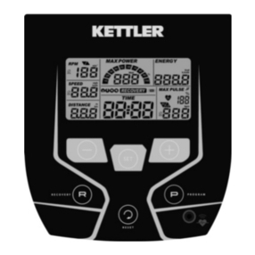
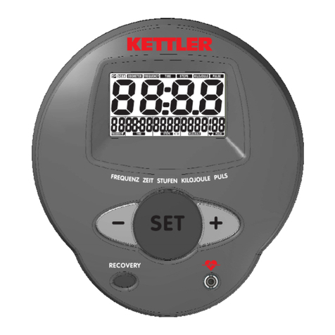
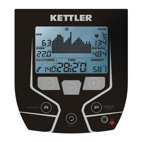
Life Gear 23500 User manual

MAGNETIC UPRIGHT BIKE PC
OWNER’S MANUAL
MODEL# 23500
The specifications of this product may vary from this photo and are subject to change without
notice. 2008, March

1
PAGE OF CONTENTS
WARRANTY 1
SAFETYINSTRUCTIONS 2
OPERATING INSTRUCTIONS 3
COMPUTEROPERATION 3
PARTSLIST 14
HARDWAREPACKINGLIST 16
OVERVIEWDRAWING 17
ASSEMBLY INSTRUCTIONS 18
TROUBLE SHOOTING GUIDE 20
WARM UPAND COOL DOWN ROUTINE 21
ONE YEAR LIMTED WARRANTY
LifeGear Inc. warrants to the original purchaser that this product is free from defects in
material and workmanship when used for the purpose intended, under the conditions that it
has been installed and operated in accordance with LifeGear's Owner's Manual. LifeGear's
obligation under this warranty is limited to replacing or repairing, free of charge, any parts
which may prove to be defective under normal home use. This warranty does not include
any damage caused by improper operation, misuse or commercial application.
From the date of purchase, the frame is warranted to be free from defects for 1 (one) year.
This warranty is extended only to the original owner and is not transferable.
When ordering replacement parts please have the following information ready:
1. Owner's Manual
2. Model Number
3. Description of Parts
4. Part Number
5. Date of Purchase

2
SAFETY INSTRUCTIONS
Basic precautions should always be followed, including the following safety
instructions when using this equipment: Read all instructions before using this
equipment.
1. Read all the instructions in this manual and do warm up exercises before using this
equipment.
2. Before exercise, in order to avoid injuring the muscle, warm-up exercise of every
position of the body is necessary. Refer to Warm Up and Cool Down Routine page.
After exercise, relaxation of the body is suggested for cool-down.
3. Please make sure all parts are not damaged and fixed well before use. This
equipment should be placed on a flat surface when using. Using a mat or other
covering material on the ground is recommended.
4. Please wear proper clothes and shoes when using this equipment; do not wear clothes
that might catch any part of the equipment; remember to tighten the pedaling straps.
5. Do not attempt any maintenance or adjustments other than those described in this
manual. Should any problems arise, discontinue use and consult an Authorized
Service Representative.
6. Do not use the equipment outdoors.
7. This equipment is for household use only.
8. Only one person should be on the equipment while in use.
9. Keep children and pets away from the equipment while in use. This machine is
designed for adults only. The minimum free space required for safe operation is not
less than two meters.
10. If you feel any chest pains, nausea, dizziness, or short of breath, you should stop
exercising immediately and consult your physician before continuing.
11. The maximum weight capacity for this product is 130kgs.
WARNING:Before beginning any exercise program consult your physician.
This is especially important for the persons who are over 35 years old or who have
pre-existing health problems. Read all instructions before using any fitness
equipment.
CAUTION:Read all instructions carefully before operating this product.
Retain this Owner’s Manual for future reference.

3
OPERATING INSTRUCTIONS
1. Operate according to your own condition.
2. Adjusting the adjustable leveler:
Turn the adjustable leveler on the rear stabilizer as needed to level the bike.
3. Adjusting the handlebar:
Hold Handlebar while loosening the T-Knob. Adjust Handlebar to the desired position
and turn the T-Knob in a clockwise direction to tighten.
Note: Continue to turn the T-Knob until Handlebar is secure before exercising.
4. Adjusting the seat post:
Turn the seat height adjusting knob in a counterclockwise direction and then pull out the
seat height adjusting knob. Lock the seat post in place by releasing the seat height
adjusting knob and sliding the seat post up or down slightly until the seat height adjusting
knob "pops" down into the locked position. For added safety, tighten the seat height
adjusting knob in a clockwise direction.
NOTE: When adjusting the height of seat post, the maximum insert depth mark
line cannot higher than the edge of bushing.
5. Adjusting the seat cushion:
Release the knob and then slide the seat cushion forth or back direction for the suitable
position. Tighten the knob after adjustment.
6. Sitting pose: sit on the seat cushion when exercising, please tighten the pedaling straps
and hold the handlebar with hands, adjust your posture according to your exercise
speed and intensity.
COMPUTER OPERATION
The things you should know before exercise
A. Input Power:
Plug in the adaptor to the equipment then the computer will produce
a beep sound and turn on the computer at the Manual mode.
B. Program select and setting value:
1. Use the UP or DOWN key to select program mode and then press
ENTER to confirm your exercise mode.
2. At the Manual mode, you may press the UP or DOWN key to set up your exercise TIME,
DISTANCE, or CALORIES.
3. Press the START/STOP key to start exercise.
4. When you reach the target, the computer will produce beep sound and then stop.
5. If you set up more than one target and you would like to reach next target, press
START/STOP key to keep on exercise.

4
C. Clock Mode:
1. After plug-in adaptor then the LCD will display at the Clock mode for user to input the
current hour by 24 hours and minute by 60 minutes. After setting up the clock then the
computer will display the hour-minute and second bar on the screen. Two seconds
display one bar. Also display the current temperature on the screen. Press any key
to quit the CLOCK mode except the ENTER key.
2. The computer will enter into the clock mode when there is no signal input or no keys be
pressed after 4 minutes. You can press the ENTER key to switch the clock and
temperature at the clock mode or press other keys to quit the clock mode except the
ENTER key.
3. By holding the ENTER and UP keys together for over two seconds, you can switch to
the CLOCK mode during the STOP mode.
4. You can set up the CLOCK by holding ENTER key for over 2 seconds when switch to
CLOCK mode from STOP mode then you can set up TIME by UP or DOWN keys.
Functions and Features:
1. Quick Start key: Allows you to start the computer without selecting a program. TIME
automatically begins to count up from zero. Use the UP and DOWN keys to adjust the
resistance.
2. TIME: Shows your elapsed workout time in minutes and seconds. Your computer will
automatically count up from 0:00 to 99:59 per 1 second increment. You can also
program your computer to count down from a set value by using the UP and DOWN
keys. If you continue exercising once the time has reached 0:00, the computer will
begin beeping, and reset itself to the original time set, letting you know your workout is
done.
3. DISTANCE: Displays the accumulative distance traveled during each workout up to a
maximum of 99.9KM/MILE.
4. RPM (Revolutions Per Minute): Your pedal cadence.
5. WATT: The amount of mechanical power the computer is receiving from your exercise.
6. SPEED: Displays your workout speed value in KM/MILE per hour.
7. CALORIES: Your computer will estimate the cumulative calories burned at any given
time during your workout.
8. PULSE: Displays your pulse rate in beats per minute during your workout.
9. AGE: Your computer is age-programmable from 10 to 99 years. If you do not set an
age, this function will always default to age 35.
10. TARGET HEART RATE (TARGET PULSE): The heart rate you should maintain is called
your Target Hear Rate in beats per minute.
11. PULSE RECOVERY: During the START stage, leave the hands holding on grips and

5
then press “PULSE RECOVERY” key, all function displays will stop except “TIME”.
Time starts counting from 00:60 - 00:59 - - to 00:00. As soon as 00:00 is reached, the
computer will display your heart rate recovery status with the grade F1.0 to F6.0.
1.0 means OUTSTANDING
1.0<F<2.0 means EXCELLENT
2.0≦F≦2.9 means GOOD
3.0≦F≦3.9 means FAIR
4.0≦F≦5.9 means BELOW AVERAGE
6.0 means POOR
Note:If no pulse signal input then the computer will show “P” on the PULSE window. If
the computer shows “ERR” on the message window, please re-press the PULSE
RECOVERY key and please make sure your hands are keeping well on the grips.
Key Function:
There are 6 button keys and the function description as follows:
1. START/STOP key: a. Quick Start key function: Allows you to start the computer without
selecting a program. Manual workout only. Time automatically begins to count up
from zero.
b. During the exercise mode, press the key to STOP exercise.
c. During the stop mode, press the key to START exercise.
2. UP key: a. Press the key to increase the resistance during exercise mode.
b. During the setting mode, press the key to increase the value of Time, Distance,
Calories, Age and select Gender and Program.
3. DOWN key: a. Press the key to decrease the resistance during exercise mode.
b. During the setting mode, press the key to decrease the value of Time, Distance,
Calories, Age and select Gender and Program.
4. ENTER/RESET key: a. During the setting mode, press the key to accept the current
data entry.
b. At the stop mode, by holding this key for over two seconds the user can reset all
values to zero or default value.
c. During setting the Clock, press this key can accept the setting hour and setting
minute.
5. BODY FAT / MEASURE key: Press the key to input your HEIGHT, WEIGHT, GENDER
and AGE then to measure your body fat ratio.
6. PULSE RECOVERY key: Press the key to activate heart rate recovery function.
Program Introduction & Operation:
Manual Program: Manual
P1 is a manual program. User can start exercise by pressing the START/STOP key. The

6
default resistance level is 5. User may exercise in any desirous of resistance level
(Adjusting by UP/DOWN key during the workout) with a period of time or a number of
calories or a certain distance.
Operations:
1. Use UP/DOWN keys to select the MANUAL (P1) program.
2. Press the ENTER key to enter MANUAL program.
3. TIME will flash and you can press the UP or DOWN key to set your exercise TIME.
Press the ENTER key to confirm your desired TIME.
4. DISTANCE will flash and you can press the UP or DOWN key to set your target
DISTANCE. Press the ENTER key to confirm your desired DISTANCE.
5. CALORIES will flash and you can press the UP or DOWN key to set your exercise
CALORIES. Press the ENTER key to confirm your desired CALORIES.
6. Press the START/STOP key to begin exercise.
Preset Program: Steps, Hill, Rolling, Valley, Fat Burn, Ramp, Mountain, Intervals,
Random, Plateau, Fartlek, and Precipice Program
PROGRAM 2 to PROGRAM 13 is the preset programs. User can exercise with different
level of loading in different intervals as the profiles show. User may exercise in any
desirous of resistance level (adjusting by UP/DOWN key during the workout) with a period of
time or a number of calories or a certain distance.
Operations:
1. Use the UP or DOWN key to select one of the above programs from P2 to P13.
2. Press the ENTER key to enter your workout program.
3. TIME will flash and you can press the UP or DOWN key to set your exercise TIME.
Press the ENTER key to confirm your desired TIME.
4. DISTANCE will flash and you can press the UP or DOWN key to set your target
DISTANCE. Press the ENTER key to confirm your desired DISTANCE.
5. CALORIES will flash and you can press the UP or DOWN key to set your exercise
CALORIES. Press the ENTER key to confirm your desired CALORIES.
6. Press the START/STOP key to begin exercise.
User Setting Program: User 1, User 2, User 3, and User 4
Program 14 to 17 is the user setting program. User is free to create the values in the order
of TIME, DISTANCE, CALORIES and the resistance level in 10 columns. The values and
profiles will be stored in the memory after setup. Users may also change the ongoing
loading in each column by UP or DOWN key, and it will not change the resistance level
stored in the memory.

7
Operations:
1. Use the UP or DOWN key to select the USER program from P14 to P17.
2. Press the ENTER key to enter your workout program.
3. The column 1 will flash, and then use the UP or DOWN key to create your personal
exercise profile. Press the ENTER key to confirm your first column of exercise profile.
The default level is load 1.
4. The column 2 will flash, and then use the UP or DOWN key to create your personal
exercise profile. Press the ENTER key to confirm your second column of exercise
profile.
5. Follow the above description to finish your personal exercise profiles. Press the
ENTER key to confirm your desired exercise profile.
6. TIME will flash and you can press the UP or DOWN key to set your exercise TIME.
Press the ENTER key to confirm your desired TIME.
7. DISTANCE will flash and you can press the UP or DOWN key to set your target
DISTANCE. Press the ENTER key to confirm your desired DISTANCE.
8. CALORIES will flash and you can press the UP or DOWN key to set your exercise
CALORIES. Press the ENTER key to confirm your desired CALORIES.
9. Press the START/STOP key to begin exercise.
Heart Rate Control Program: 55% H.R.C., 65% H.R.C., 75% H.R.C., 85% H.R.C., and
Target H.R.C.
Program 18 to Program 22 is the Heart Rate Control Programs and Program 22 is the Target
Heart Rate Control program.
Program 18 is the 55% Max H.R.C. - - Target H.R. = (220 – AGE) x 55%
Program 19 is the 65% Max H.R.C. - - Target H.R. = (220 – AGE) x 65%
Program 20 is the 75% Max H.R.C. - - Target H.R. = (220 – AGE) x 75%
Program 21 is the 85% Max H.R.C. - - Target H.R. = (220 – AGE) x 85%
Program 22 is the Target H.R.C. - - Workout by your target heart rate value.
User can exercise according to your desired Heart Rate program by setting your AGE, TIME,
DISTANCE, CALORIES or TARGET PULSE. In these programs, the computer will adjust
the resistance level according to the heart rate detected. For example, the resistance level
may increase every 20 seconds while the heart rate detected is lower than the TARGET H.R
and then the computer will show “SLOW DOWN” on the message window. Also the
resistance level may decrease every 20 seconds while the heart rate detected is higher than
the TARGET H.R and then the computer will show “HURRY UP” on the message window.
As a result, the user’s heart rate will be adjusted to close the TARGET H.R. between the
range of TARGET H.R. +5 and TARGET H.R. -5 and then the computer will show “KEEP

8
GOING” on the message window.
Operations:
1. Use UP or DOWN key to select one of the heart rate control program from P18 to P22.
2. Press the ENTER key to enter your workout program.
3. AGE will flash at P18 to P21 programs and you can press the UP or DOWN key to set
your AGE. The default age is 35.
4. At the program 22, the TARGET PULSE will flash and you can press the UP or DOWN
key to set your TARGET PULSE between 80 to 180. The default TARGET PULSE is
120.
5. TIME will flash and you can press the UP or DOWN key to set your exercise TIME.
Press the ENTER key to confirm your desired TIME.
6. DISTANCE will flash and you can press the UP or DOWN key to set your target
DISTANCE. Press the ENTER key to confirm your desired DISTANCE.
7. CALORIES will flash and you can press the UP or DOWN key to set your exercise
CALORIES. Press the ENTER key to confirm your desired CALORIES.
8. Press the START/STOP key to begin exercise.
Watt Control Program: Watt Control
Program 23 is a Speed Independent Program. Press the ENTER key to set up the values
of TARGET WATT, TIME, DISTANCE and CALORIES. During the exercise mode, the level
of resistance is not adjustable. For example, the level of resistance may increase while the
speed is too slow. Also the level of resistance may decrease while the speed is too fast.
As a result, the calculated value of WATT will close to the value of TARGET WATT setup by
users.
Operations:
1. Use the UP or DOWN key to select the WATT CONTROL (P23) program.
2. Press the ENTER key to enter your workout program.
3. TIME will flash and you can press the UP or DOWN key to set your exercise TIME.
Press the ENTER key to confirm your desired TIME.
4. DISTANCE will flash and you can press the UP or DOWN key to set your target
DISTANCE. Press the ENTER key to confirm your desired DISTANCE.
5. WATT will flash and you can press the UP or DOWN key to set your target WATT value.
Press the ENTER key to confirm your target WATT. The default WATT value is 100.
6. CALORIES will flash and you can press the UP or DOWN key to set your exercise
CALORIES. Press the ENTER key to confirm your desired CALORIES.
7. Press the START/STOP key to begin exercise.
NOTE: 1. WATT = TORQUE (KGM) * RPM * 1.03
2. In this program, the WATT value will keep constant value. It means that if you

9
peddle quickly, the resistance level will decrease and if you peddle slowly, the
resistance level will increase. Always try to keep you in the same watt value.
Body Fat Program: Body Fat
Program 24 is a special program design to calculate user’s body fat ratio and to offer a
specific loading profile for user. There are 3 body types divided according to the FAT%
calculated.
Type1: BODY FAT% > 27
Type2: 27 ≧BODY FAT% ≧20
Type3: BODY FAT % < 20
The computer will show the test results of FAT PERCENT, BMI and BMR.
Operations:
1. Use the UP or DOWN key to select the BODY FAT (P24) program.
2. Press the ENTER key to enter your workout program.
3. HEIGHT will flash and you can press the UP or DOWN key to set your HEIGHT. Press
the ENTER key to confirm your HEIGHT. The default HEIGHT is 170cm or 5’07” (5
feet 7 inches).
4. WEIGHT will flash and you can press the UP or DOWN key to set your WEIGHT.
Press the ENTER key to confirm your WEIGHT. The default WEIGHT is 70kgs or
155lbs.
5. GENDER will flash and you can press the UP or DOWN key to select your gender.
Number 1 means male and number 0 means female. Press the ENTER key to confirm
your Gender. The default gender is 1 (FEMALE).
6. AGE will flash and you can press the UP or DOWN key to set your AGE. Press the
ENTER key to confirm your AGE. The default AGE is 35.
7. Press the START/STOP key to begin body fat measurement. If the window shows E,
please make sure your hands are attached well on the grips. Then press the
START/STOP key again to begin body fat measurement.
8. After finished your measurement, the computer will show the values of BMR, BMI and
FAT PERCENT on the LCD display. Furthermore, the computer will show your own
exercise profile for your body type.
9. Press the START/STOP key to begin exercise.
Operation Guide:
1. Sleep Mode:
The computer will enter the sleep mode when there is no signal input and no keys be
pressed after 4 minutes. You can press any key to wake up the computer.

10
2. BMI (Body Mass Index): BMI is a measure of body fat based on height and weight that
applies to both adult men and women.
3. BMR (Basal Metabolic Rate): Your Basal Metabolic Rate (BMR) shows the number of
calories your body needs to operate. This doesn’t account for any activity, it’s simply
the energy needed to sustain a heartbeat, breathing and normal body temperature. It
measures the body at rest, not sleep, at room temperature.
Error Message:
E1 (ERROR 1):
Normal state: During workout, when the computer did not get the count signal from the gear
motor more than 4 seconds and check under successive 3 times then the LCD will show E1.
Power on state: The gear motor will return to zero automatically, when the signal of motor
cannot be detected for more than 4 seconds then the gear motor’s driver will be cut off
immediately and show the E1 on the LCD display. All the other digital and function mark
are blank, and the output signals are cut off also.
E2 (ERROR 2):
When the computer reads the memory data, if the I.D. code is not correct or the memory IC
damages then the computer will show E2 immediately at power on.
E3 (ERROR 3):
After 4 seconds by start mode, the computer detects the faulty motor did not leave the zero
point then the LCD bar displays “E3”.
LCD Workout Graphics
PRESET PROGRAM PROFILES:
PROGRAM1 PROGRAM2 PROGRAM3
MANUAL STEPS HILL

11
PROGRAM4 PROGRAM5 PROGRAM6
ROLLING VALLEY FAT BURN
PROGRAM7 PROGRAM8 PROGRAM9
RAMP MOUNTAIN INTERVALS
PROGRAM10 PROGRAM11 PROGRAM12
RANDOM PLATEAU FARTLEK
PROGRAM13
PRECIPICE
USER SETTING PROGRAM:
PROGRAM14
USER1
PROGRAM 15
USER2

12
PROGRAM 16
USER3
PROGRAM 17
USER4
HEART RATE PROGRAM PROFILES:
PROGRAM18
55% H.R.C.
Press ENTER key
PROGRAM19
65%H.R.C.
Press ENTER key
PROGRAM 20
75% H.R.C.
Press ENTER key
PROGRAM 21
85% H.R.C.
Press ENTER key

13
PROGRAM 22
TARGET H.R.C.
WATT CONTROL PROGRAM:
PROGRAM 23
WATT CONTROL
BODY FAT TEST PROGRAMS:
PROGRAM24
BODYFAT(STOPMODE) BODYFAT(STARTMODE)
One of the Following Six Profiles Will Display Automatically after Measuring Your
BODY FAT:
Workout Time: 40 minutes Workout Time: 40 minutes Workout time: 20 minutes

14
PARTS LIST
No. Description Qty No. Description Qty
001 Main Frame 1 033 Nut 3/8"x26x3mm 2
002 Front Stabilizer 1 034 Nut 3/8"x26x9mm 1
003 Rear Stabilizer 1 035 Nut M6 1
004 Front Post 1 036 Spring Washer M6 4
005 Seat Post 1 037 Spring Washer M8 10
006 Seat Sliding Tube 1 038 Washer M6x16x1.5 3
007 U Bracket for Seat Sliding Tube 1 039 Washer M8x16x1.2 10
008 Handlebar 1 040 Washer Ø10xØ13x0.3 3
009 Idle Wheel Bracket 1 041 Washer M10x20x1 1
010 Magnet Bracket 1 042 Washer M10ר21×2 1
011 Front Pulley 1 043 Washer M6x19x1.5 1
012 Flywheel 1 044 Rubber Washer Ø6xØ22x1 1
013 Flywheel Axle 1 045 C Clip C10 2
014 Belt Pulley 1 046 C Clip C17 3
015 Axle 1 047 Bearing 6003ZZ 2
016 Spacer 3 048 Bearing 6300ZZ 1
017 Bolt M6x14 3 049 Bearing 6203ZZ 4
018 Bolt M8x52 1 050 Bearing 6000ZZ 1
019 Bolt M5x10 (BK) 4 051 One Way Bearing 1
020 Bolt M6x16 4 052 Large Spring 2.6x20x83L 1
021 Bolt M8x15 8 053 Spring 1.2x55L 1
022 Carriage Bolt M8x52 2 054 Handlebar Foam Grip 2
023 Screw M4x15 1 055 Round Plug Ø22.2x1.5 2
024 Bolt M6x65 1 056 Square Plug 30x60 1
025 Bolt M8x1x25 2 057 Sensor Bracket 1
026 Bolt M5x10 (UCP) 2 058 Left Front Stabilizer End Cap 1
027 Screw M3x12 2 059 Right Front Stabilizer End Cap 1
028 Screw M4x25 (UCP) 2 060 Rear Stabilizer End Cap 2
029 Screw M4x8 2 061 Adjustable Leveler 2
030 M8 Nylon Nut 3 062 Seat Height Adjusting Knob 1
031 M6 Nylon Nut 5 063 T-Knob 1
032 Nut 3/8"x26 1 064 Square Plug 40x40 2

15
PARTS LIST
No. Description Qty No. Description Qty
065 Knob 3/8"-16 1 082 Back Handlebar Cover 1
066 Magnet 1 083 Wire Plug 1
067 Belt 430J6 1 084 Plastic Tube 1
068L Left Pedal JD-22A 1 085 Computer B31132 1
068R Right Pedal JD-22A 1 086 Hand Pulse Sensor (S1001) 2
069 Seat Cushion A16 1 087 Adaptor 1
070 Bushing 1 088 Motor with Cable 1
071 Bolt Cap M8xØ19 2 089 Sensor Wire (L=250mm) 1
072L Left Crank 1 090 Sensor Wire I (L=7500mm) 1
072R Right Crank 1 091 Sensor Wire II (L=700mm) 1
073 Crank Cover 2 092 Bottom Section Power Supply
Cable 1
074 Left Shroud 23500 1 093 Hand Pulse Wire 560/650L 1
075 Right Shroud 23500 1 094 Wire Rod 1
076 Round Plug 2 095 Bolt M5x12 4
077 Front Post Cover 1 096 Screw M4x25 (BK) 6
078 Seat Post Cover 1 097 Screw Mx18 2
079 Left Seat Sliding Tube 1 098 Power Fixed Plate 1
080 Right Seat Sliding Tube 1 099 Screw M5x20 4
081 Front Handlebar Cover 1 100 Nut M8 2

16
HARDWARE PACKING LIST
(21) Bolt M8x15
8 PCS
(28) Screw M4x25
(UCP)
2 PCS
(27) Screw M3x12
2 PCS
(26) Bolt M5x10 (UCP)
2 PCS
(37) Spring Washer M8
10 PCS
(30) M8 Nylon Nut
2 PCS
(29) Screw M4x8
2 PCS
(62) Seat Height Adjusting Knob
1 PC
(39) Washer M8x16x1.2
10 PCS (71) Bolt Cap M8xØ19
2 PCS
A
llen Wrench 6mm/
Screwdriver
1 PC
Wrench 10mm, 13mm,
14mm, 15mm
1 PC
(22) Carriage Bolt
M8x52
2 PCS

17
OVERVIEW DRAWING

18
ASSEMBLY INSTRUCTIONS
1. Install the Front Stabilizer.
Attach the Front Stabilizer (2) onto the front curve
plate of Main Frame (1) with two M8x52 Carriage
Bolts (22), M8x16x1.2 Washers (39), M8 Spring
Washers (37), and M8 Nylon Nuts (30). Finally,
cover the M8 Nylon Nuts (30) with two M8xØ19 Bolt
Caps (71).
2. Install the Rear Stabilizer.
Attach the Rear Stabilizer (3) onto the rear end of the
Main Frame (1) with four M8x15 Bolts (21), M8
Spring Washers (37), and M8x16x1.2 Washers (39).
3. Install the Front Post Cover and Front Post.
Insert the Front Post (4) into the Front Post Cover
(77). Connect the Sensor Wire II (91) from the
Main Frame (1) to the Sensor Wire I (90) from the
Front Post (4). Insert the Front Post (4) into the
tube of the Main Frame (1) and secure with four
M8x15 Bolts (21), M8 Spring Washers (37), and
M8x16x1.2 Washers (39).
1
2
3

19
4. Install the Seat Cushion, Seat Post and
Left/Right Seat Sliding Tubes.
Release both M8 Nuts (100) just a little bit from
underneath of the Seat Cushion (69) and then attach
the Seat Sliding Tube (6) with Seat Post (5) onto the
hole that underneath of the Seat Cushion (69).
Tighten both M8 Nuts (100) after adjustment.
Attach the Seat HeightAdjusting Knob (62) onto the
tube of Main Frame (1) on the Seat Post Cover (78)
by turning it in a clockwise direction. Release the
Seat Height Adjusting Knob (62) by turning it in a
counterclockwise direction until it can be pulled out.
Pull out the Seat Height Adjusting Knob (62) and
slide the Seat Post (5) into the bushing on the tube
of the Main Frame (1). Lock the Seat Post (5) in
place by releasing the Seat Height Adjusting Knob
(62) and sliding the Seat Post (5) up or down slightly
until the Seat Height Adjusting Knob (62) "pops"
down into the locked position. For added safety,
tighten the Seat Height Adjusting Knob (62) in a
clockwise direction.
Attach the Left and Right Seat Sliding Tube Covers
(79, 80) onto the top end of the Seat Post (5) with
two M4x25 (UCP) Screws (28) and M4x8 Screws
(29).
NOTE: When adjusting the height of seat post,
the maximum insert depth mark line cannot
higher than the edge of bushing.
5. Install the Handlebar and Computer.
Install the Handlebar (8) to the groove of the Front
Post (4). Insert the Hand Pulse Wire (93) into the
hole on the Front Post (4) and then pull it out from
the top end of the Front Post (4). Install the Wire
Plug (83) onto the hole on the Front Post (4).
Remove four M5x12 Bolts (95) from the Computer
(85). Connect the Hand Pulse Wire (93) and
Sensor Wire I (90) to the wires that come from the
Computer (85) and then attach the Computer (85)
onto the top end of the Front Post (4) with four
M5x12 Bolts (95) that were removed.
Attach the Front and Back Handlebar Covers (81, 82)
onto the Handlebar (8) and Front Post (4) with two
M5x10 (UCP) Bolts (26) and M3x12 Screws (27).
Tighten the T-Knob (63) after adjustment.
6. Install the Pedals and Adaptor.
Attach the Right and Left Pedals (68R, 68L) to the
Right and Left Cranks (72R, 72L). The Right Pedal
(68R) should be threaded in a clockwise direction.
The Left Pedal (68L) should be threaded in a counterclockwise direction.
Plug the wire of the Adaptor (87) into the power jack on the rear side of the Left Shroud (74)
and then connect the Adaptor (87) to the electrical wall outlet.
NOTE: The Right and Left Pedals (68R, 68L) and Right and Left Cranks (72R, 72L) are
marked with “R” & “L”.
4
5
6
Table of contents