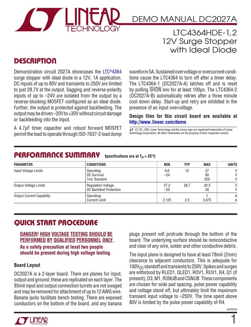
Linear Technology LTC2393-16 Quick setup guide

1
dc1501A
DEMO MANUAL DC1501A
DESCRIPTION
LTC2393-16/LTC2392-16/
LTC2391-16, 1MSPS, 0.5MSPS,
0.25MSPS Low Noise ADC
The LTC2393-16 family are low noise high speed ADCs
with both parallel and serial outputs that can operate from
a single 5V supply. The LTC2393-16 family supports a
large ±4.096V fully differential input range. This makes
them ideal for high performance applications that require
maximum dynamic range. Demonstration circuit 1501A
provides the user a means of evaluating the performance
of these ADCs in both parallel and serial modes and is L, LT, LTC, LTM, Linear Technology and the Linear logo are registered trademarks of Linear
Technology Corporation. All other trademarks are the property of their respective owners.
intended to demonstrate recommended grounding, part
placement, routing and bypassing for this family of parts.
Also several suggested driver circuits for the analog inputs
will be presented.
Design files for this circuit board are available at http://
www.linear.com/demo.
Figure 1. DC1501A Connection Diagram
–9V +9VGND
TO
DC718
CLK IN
1MHz MAX
(80MHz FOR SERIAL)
3.3VPK-PK MAXIMUM
AIN–
0V TO 4.096V
MAXIMUM
AIN+
0V TO 4.096V
MAXIMUM
DEMO BOARD IC MAX SAMPLE RATE PARALLEL MAX CLK IN SERIAL MAX CLK IN
DC1501A-A LTC2393CLX-16 1Msps 1MHz 80MHz
DC1501A-B LTC2392CLX-16 0.5Msps 0.5MHz 40MHz
DC1501A-C LTC2391CLX-16 0.25Msps 0.25MHz 20MHz

2
dc1501A
DEMO MANUAL DC1501A
DC718B/C QUICK START PROCEDURE
Check to make sure that all switches and jumpers are
set as shown in the connection diagram of Figure 1. The
default connections configure the ADC for parallel opera-
tion with the output data in offset binary format. The
analog input is AC-coupled and the internal reference of
the ADC is used.
Connect DC1501A to a DC718B/C USB High Speed Data
Collection Board using connector J1. Connect DC718B/C
to a host PC with a standard USB A/B cable. Apply ±9V to
the indicated terminals. Apply a low jitter signal source to
J17. The default setup uses a single-ended to differential
converter so that it is only necessary to apply an input
signal to J17. Connect a low jitter 1MHz 3.3VP-P sine wave
or square wave to connector J16 for LTC2393-16. Apply
500kHz for LTC2392-16 and 250kHz for LTC2391-16.
Note that J16 has a 50Ω termination resistor to ground.
Run the QuickEval-II software (Pscope.exe version K66
or later) supplied with DC718B/C or download it from
www.linear.com.
Complete software documentation is available from the
Help menu. Updates can be downloaded from the Tools
menu. Check for updates periodically as new features
may be added.
The Pscope software should recognize DC1501A and
configure itself automatically.
Click the Collect button (See Figure 6) to begin acquiring
data. The Collect button then changes to Pause, which
can be clicked to stop data acquisition.
DC1501A SETUP
DC Power
DC1501 requires ±9VDC at approximately 100mA. Most
of the supply current is consumed by the CPLD, op amps,
regulators and discreet logic on the board. The ±9VDC
input voltage powers the ADC through LT1763 regulators
which provide protection against accidental reverse bias.
Additional regulators provide power for the CPLD and
op amps. See Figure 1 for connection details.
Clock Source
You must provide a low jitter 3.3VP-P sine or square wave
to J16. The clock input is AC-coupled so the DC level of the
clock signal is not important. A generator like the HP8644
or similar is recommended.Even a good generatorcan start
to produce noticeable jitter at low frequencies. Therefore
it is recommended for lower sample rates to divide down
a higher frequency clock to the desired sample rate. One
way to accomplish this is by placing the ADC in the serial
mode. This can be accomplished by setting the SER/PARL
position of SW1 to the high position. In the serial mode
the ratio of clock frequency to conversion rate is 80:1.
This limits the max clock frequency of DC1501A-A to
80MHz in serial mode. DC1501A-B is limited to 40MHz and
DC1501A-C is limited to 20MHz. In the parallel mode there
is a 1:1 ratio of clock frequency to conversion rate. If the
clockinput isto bedriven withlogic, itis recommendedthat
the 50Ω terminator (R17) be removed. Slow rising edges
may compromise SNR of the converter in the presence of
high-amplitude higher frequency input signals.
Data Output
Parallel data output from this board (0V to 3.3V default),
if not connected to DC718, can be acquired by a logic
analyzer, and subsequently imported into a spread-sheet,
ormathematical packagedepending onwhat formof digital
signal processing is desired. Alternatively, the data can be
fed directly into an application circuit. Use pin 3 of J1 to
latch the data. The data can be latched using either edge
of this signal. The data output signal levels at J1 can also
be reduced to 0V to 2.5V if the application circuit cannot
tolerate the higher voltage. Thisis accomplished by moving
J13 to the 2.5V position.

3
dc1501A
DEMO MANUAL DC1501A
Figure 2. Single-Ended to Differential Converter
Reference
J7, J8 and J11 allow you to select an on chip reference
or an external LT1790A-4.096 as the reference. The initial
tolerance and drift specifications of the external reference
are better than the on chip reference. To use the internal
reference set J7 to FLT, J8 to ADC and J11 to REFIN. To use
the LT1790A-4.096 set J7 and J11 to GND and J8 to EXT.
Analog Input
The default driver for the analog inputs of the LTC2393
family on DC1501A is shown in Figure 2. This circuit
converts a single-ended 0V to 4.096V input signal applied
at AIN into a differential signal with a swing of ±4.096V
between the +IN and –IN inputs of the ADC. In addition this
circuit band limits the input frequencies to approximately
100kHz which is the useful bandwidth of these ADCs.
Alternatively, if your application circuit produces a differ-
ential signal which can drive the ADC but you need to
level shift the input signal, the circuits of Figure 3 and
Figure 4 can be used. The circuit of Figure 3 AC-couples
the input signal and is usable down to about 10kHz. The
lower frequency limit can be extended by increasing C37
and C51. The circuit of Figure 3 can be implemented on
DC1501A by putting J20 and J21 in the AC position and
moving R2 and R3 to the R50 and R53 positions. One of
these RC pairs can be attached to the input of the circuit in
Figure 2. This allows a single-ended input signal to be level
shifted. This is the default condition for DC1501A. Figure
4’s input driver allows the input voltage range to go below
ground. It DC-couples and level shifts the analog input at
the expense of attenuating the input level by a factor of 2.
The circuit of Figure 4 can be implemented on DC1501A
by setting VCM to External and biasing the external pin to
4.096V replacing R1 and R6 with 1kΩ, putting J20 and
J21 in the DC position and moving R2 and R3 to the R50
and R53 positions.
For SINAD, THD or SNR testing a low noise, low distortion
generatorsuch asthe B&KType 1051or StanfordResearch
DS360 should be used.
DC1501A SETUP

4
dc1501A
DEMO MANUAL DC1501A
Data Collection
This demoboard istestedin housebyduplicating theFFT plot
shown in theADC data sheet. Thisinvolves using alow jitter,
1MHz (500kHz for LTC2392-16, 250kHz for LTC2391-16)
clock source for the encode clock, along with a low noise,
low distortion sinusoidal generatorat a frequency of 20kHz.
The input signal level is approximately –1dBfs.
The input is filtered with a 20kHz single pole RC filter
shown in Figure 5. The FFT shown in the data sheet is a
16384-point FFT. A typical FFT obtained with DC1501A
is shown in Figure 6. Note that to get the real SNR, the
DC1501A SETUP
Figure 3. AC-Coupled Differential Driver
Figure 4. DC Coupled Differential Driver
signal level (–1dB) has to be added back to the SNR that
PScope displays. With the example shown in Figure 6 this
means that the actual SNR would be 94.061dB. Taking the
RMS sum of the recalculated SNR and the THD yields a
SINAD of 93.75dB which is fairly close to the typical value
for this ADC.
There are a number of scenarios that can produce
misleading results when evaluating an ADC. One that is
common is feeding the converter with a frequency, that
is a sub-multiple of the sample rate, and which will only
exercise a small subset of the possible output codes.

5
dc1501A
DEMO MANUAL DC1501A
If you do not have a signal generator capable of ppm levels
of frequency accuracy or if it cannot be slaved to the clock
frequency, you can use an FFT with windowing to reduce
the “leakage” or spreading of the fundamental, to get a
close approximation of the performance parameters. If an
amplifier or clock source with poor phase noise is used,
the windowing will not improve the SNR.
The signal source typically usedfor in housetesting is aB&K
1051. A lowjitter RFoscillator such asthe HP8644is used as
the clocksource. Aswith anyhighperformance ADC,this part
is sensitive to layout. The area immediately surrounding the
ADC onDC1501 shouldbeused asa guidelineforplacement,
and routing of the various components associated with the
ADC. Note should also be taken of the ground plane used
in the layout of this board.
DC1501A SETUP
Figure 5. 20kHz RC filter
Figure 6. DC1501A FastDAACS Screenshot

6
dc1501A
DEMO MANUAL DC1501A
DC1501A MISCELLANEOUS DIP SWITCHES AND JUMPERS
Definitions
J2- -INPUT sets the bias point for the –input of U2A. The
default is –AIN.
J6- VCM sets the DC bias for AIN+and AIN–when the inputs
are AC-coupled. INT is the default position.
SW1-
SER_PARL- Selects serial or parallel operation. Default
position is parallel. In parallel mode fs= fclk. In serial mode
fs = fclk/80.
OB/2CL- Selects offset binary or two’s complement
data format for ADC output word. The default is offset
binary.
CSL- This pin must be kept low for normal operation.
RDL- This pin must be kept low for normal operation.

7
dc1501A
DEMO MANUAL DC1501A
PARTS LIST
ITEM QUANTITY REFERENCE DESIGNATOR DESCRIPTION MANUFACTURERS PART NUMBER
REQUIRED CIRCUIT COMPONENTS:
1 0 C1, C9, C39, C52, C54, C55
(opt.)
CAP., 0603
2 1 C2 CAP., NP0, 2200pF, 25V, 5% 1206 AVX, 12063A222JAT2A
3 11 C4, C5, C7, C12, C16,
C23-C25, C33, C36, C41
CAP., X7R, 1μF, 16V, 10% 0603 AVX, 0603YC105KAT2A
4 9 C10, C18, C20, C22, C28,
C30, C37, C51, C53
CAP., X5R, 10μF, 6.3V, 20% 0603 Taiyo Yuden, JMK107BJ106MA (2rls, PbF)
5 2 C13, C14 CAP., X5R, 10μF, 10V, 20% 0805 Taiyo Yuden, LMK212BJ106MG
6 9 C11, C27, C29, C31, C32,
C34, C35, C38, C50
CAP., X7R, 0.1μF, 25V, 10% 0603 AVX, 06033C104KAT2A
7 4 C15, C17, C19, C21 CAP., X7R, 0.01μF, 50V, 10% 0603 AVX, 06035C103KAT2A
8 1 C26 CAP., X5R, 47μF, 16V, 20% 1210 Taiyo Yuden, EMK325BJ476MM
9 1 C40 CAP., X5R, 4.7μF, 4V, 20% 0402 Taiyo Yuden, AMK105BJ475MV-F
10 8 C42-C49 CAP., X5R, 0.1μF, 10V, 10% 0402 AVX, 0402ZD104KAT2A
11 9 E1-E9 Testpoint, Turret, .061” pbf MILL-MAX, 2308-2-00-80-00-00-07-0
12 1 J1 Header, .1 ×.1 CNTRS, 40-Pin Samtec, TSW-120-07-L-S
13 1 JTAG 0.1” × 5 Double Row Header Samtec, TSW-105-07-L-D
14 1 J2 0.1” × 3 Double Row Header Samtec, TSW-103-07-L-D
15 6 J6, J7, J8, J11, J20, J21 3-Pin 0.1” Single Row Header Samtec, TSW-103-07-L-S (PbF)
16 8 XJTAG, XJ2, XJ6-J8, XJ11,
XJ19-J21
Shunt, 0.1” Center Samtec, SNT-100-BK-G (PbF)
17 1 J13 3-Pin 2mm Single Row Header Samtec, TMM103-02-L-S
18 1 XJ13 Shunt, 2mm Center Samtec, 2SN-BK-G
19 3 J16, J17, J18 CONN, BNC, 5-Pins Connex, 112404
20 2 R1, R6 RES., Chip, 0, 1/10W, 0603 Vishay, CRCW06030000Z0EA
21 2 R2, R3 RES., Chip, 249, 1/10W, 1% 0603 Vishay, CRCW0603249RFKEA
22 3 R4, R5, R7 RES., Chip, 301, 1/10W, 1% 0603 Vishay, CRCW0603301RFKEA
23 3 R8, R9, R10 RES., Chip, 4.99k, 1/10W, 1% 0603 Vishay, CRCW06034K99FKEA
24 3 R11, R12, R28 RES., Chip, 1k, 1/10W, 5% 0603 Vishay, CRCW06031K00JNEA
25 2 R15, R13 RES., Chip, 3.92k, 1/10W, 1% 0603 Vishay, CRCW06033K92FKEA
26 6 R14, R16, R18, R19, R30,
R37
RES., Chip, 1.00k, 1/10W, 1% 0603 Vishay, CRCW06031K00FKEA
27 1 R17 RES., Chip, 49.9, 1/4W, 1% 1206 Vishay, CRCW120649R9FKEA
28 3 R20, R22, R49 RES., Chip, 33, 1/10W, 5% 0603 Vishay, CRCW060333R0JNEA
29 1 R24 RES., Chip, 1.0, 1/10W, 5% 0603 Vishay, CRCW06031R00JNEA
30 1 R25 RES., Chip, 1.69k, 1/10W, 1% 0603 Vishay, CRCW06031K69FKEA
31 1 R26 RES., Chip, 1.54k, 1/10W, 1% 0603 Vishay, CRCW06031K54FKEA
32 1 R27 RES., Chip, 2.80k, 1/10W, 1% 0603 Vishay, CRCW06032K80FKEA
33 0 R29, R36, R38, R50, R53,
R55(opt)
RES., Chip, 0603
34 4 R31, R32, R33, R34 RES., Chip, 1k, 1/16W, 5% 0402 Vishay, CRCW04021K00JNED
35 5 R35, R40, R41, R42, R43 RES., Chip, 10k, 1/16W, 5% 0402 Vishay, CRCW040210K0JNED
36 4 R45, R46, R47, R48 RES., Chip, 300, 1/16W, 5% 0402 Vishay, CRCW0402300RJNED

8
dc1501A
DEMO MANUAL DC1501A
ITEM QUANTITY REFERENCE DESIGNATOR DESCRIPTION MANUFACTURERS PART NUMBER
REQUIRED CIRCUIT COMPONENTS:
37 2 R51, R52 RES., Chip, 49.9, 1/16W, 1% 0402 Vishay, CRCW040249R9FKED
38 1 R54 RES., Chip, 10k, 1/10W, 5% 0603 Vishay, CRCW060310K0JNEA
39 1 SW1 Switch, 219-4MST, CTS Electronic Components, 219-4MST
40 1 U2 IC., LT1807CMS8 MSOP-8 Linear Tech., LT1807CMS8#TRPBF
41 1 U4 IC., 24LC025 TSSOP-8 Microchip., 24LC025-T/ST
42 1 U5 IC., LT1790ACS6-4.096, SOT23-6 Linear Tech., LT1790ACS6-4.096#PBF
43 1 U6 IC., LT1763CS8-1.8, SO8 Linear Tech., LT1763CS8-1.8#PBF
44 2 U9, U7 IC., LT1763CS8, SO8 Linear Tech., LT1763CS8#PBF
45 1 U8 IC., LT1763CS8-5, SO8 Linear Tech., LT1763CS8-5#PBF
46 1 U10 IC., LT1964ES5-SD, SOT23-5 Linear Tech., LT1964ES5-SD#PBF
47 1 U12 IC., NL17SZ74, US8 On SEMI., NL17SZ74USG
48 1 U13 IC., NC7ST04P5X SC70-5 Fairchild, NC7ST04P5X
49 1 U14 IC., EPM240GT100C5N TQFP-100 Altera Corp., EPM240GT100C5N
50 1 U15 IC., NC7SZ04P5X SC70-5 Fairchild, NC7SZ04P5X
51 1 U16 IC., NC7SVU04P5X SC70-5 Fairchild, NC7SVU04P5X
52 4 (Stand-Off) Stand-Off, Nylon 0.25” Keystone, 8831(Snap On)
53 1 Fab, Printed Circuit Board Demo Circuit 1501A
1 DC1501A-A
1 1 DC1501A General BOM
2 1 U1 IC., LTC2393CLX-16, LQFP-7X7, 48-Pin Linear Tech., LTC2393CLX-16#PBF
DC1501A-B
1 1 DC1501A General BOM
2 1 U1 IC., LTC2392CLX-16 LQFP-7X7, 48-Pin Linear Tech,. LTC2392CLX-16#PBF
DC1501A-C
1 1 DC1501A-C General BOM
2 1 U1 IC., LTC2391CLX-16 LQFP-7X7, 48-Pin Linear Tech,. LTC2391CLX-16#PBF
PARTS LIST

9
dc1501A
DEMO MANUAL DC1501A
SCHEMATIC DIAGRAM
5
5
4
4
3
3
2
2
1
1
DD
CC
BB
AA
FLT
EXT_VCM
80MHz MAX
CLK
3.3VPP
AIN+
0V - 4.096V
AIN-
0V - 4.096V
-INPUT
2.048V
GND
-AIN
VCM EXT
INT
REFSNS
GND
REFIN
EXT ADC
REFOUT
REFIN GND
CSL
RDL
HIGH
LOW
-COUPLING
AC DC
DC
AC
+COUPLING
SER_PARL
OB/2CL
VREF
+3.3V
+3.3V
+5V
+3.3V
+3.3V
BUSY
D17
D16
D15
D14
D13/SCLK
D12/SDOUT
D11/SDIN
D10
D9
D7
D6
D5
D4
D3
D2
BYTESWAP_D1/A1
GND_D0/A0
OB2C
SER_PARL_MODE0
GND_MODE1
CLK
CNVSTL
VCM
VCM
VREF
VCM_BIAS
VCM_BIAS
VCM_BIAS
SER_PARL 16_18L
D8
DB0
DB1
DB2
DB3
DB4
DB5
DB6
DB7
DB8
DB13
DB12
DB11
DB9
DB10
DB14
DB15
CLKOUT
CNVST_33 DB16
DB17
SIZE
DATE:
IC NO.
REV
SHEET OF
TITLE:
CONTRACT NO.
APPROVALS
PCB DES.
ENG.
TECHNOLOGY
Fax: (408)434-0507
Milpitas, CA 95035
Phone: (408)432-1900
1630 McCarthy Blvd.
LTC Condential-For Customer Use Only
CUSTOMER NOTICE
LINEAR TECHNOLOGY HAS MADE A BEST EFFORT TO DESIGN A
CIRCUIT THAT MEETS CUSTOMER-SUPPLIED SPECIFICATIONS;
HOWEVER, IT REMAINS THE CUSTOMER'S RESPONSIBILITY TO
VERIFY PROPER AND RELIABLE OPERATION IN THE ACTUAL
APPLICATION. COMPONENT SUBSTITUTION AND PRINTED
CIRCUIT BOARD LAYOUT MAY SIGNIFICANTLY AFFECT CIRCUIT
PERFORMANCE OR RELIABILITY. CONTACT LINEAR
TECHNOLOGY APPLICATIONS ENGINEERING FOR ASSISTANCE.
THIS CIRCUIT IS PROPRIETARY TO LINEAR TECHNOLOGY AND
SCHEMATIC
SUPPLIED FOR USE WITH LINEAR TECHNOLOGY PARTS.
2
DEMO CIRCUIT 1501A
Thursday, October 29, 2009
1
2
K. TRAN
G. HOOVER
LOW NOISE HIGH SPEED SAR ADC FAMILY
LTC23XXCLX FAMILY
B
SCALE: NONE
SIZE
DATE:
IC NO.
TITLE:
CONTRACT NO.
APPROVALS
PCB DES.
ENG.
TECHNOLOGY
Fax: (408)434-0507
Milpitas, CA 95035
Phone: (408)432-1900
1630 McCarthy Blvd.
LTC Condential-For Customer Use Only
CUSTOMER NOTICE
LINEAR TECHNOLOGY HAS MADE A BEST EFFORT TO DESIGN A
CIRCUIT THAT MEETS CUSTOMER-SUPPLIED SPECIFICATIONS;
HOWEVER, IT REMAINS THE CUSTOMER'S RESPONSIBILITY TO
VERIFY PROPER AND RELIABLE OPERATION IN THE ACTUAL
APPLICATION. COMPONENT SUBSTITUTION AND PRINTED
CIRCUIT BOARD LAYOUT MAY SIGNIFICANTLY AFFECT CIRCUIT
PERFORMANCE OR RELIABILITY. CONTACT LINEAR
TECHNOLOGY APPLICATIONS ENGINEERING FOR ASSISTANCE.
THIS CIRCUIT IS PROPRIETARY TO LINEAR TECHNOLOGY AND
SCHEMATIC
SUPPLIED FOR USE WITH LINEAR TECHNOLOGY PARTS.
DEMO CIRCUIT 1501A
K. TRAN
G. HOOVER
LTC23XXCLX FAMILY
B
SCALE: NONE
REVISION HISTORY
DESCRIPTION DATE
APPROVED
ECO REV
G. HOOVERPRODUCTION
210-29-09
1
ECO REV
PRODUCTION
210-29-09
1
1
R10
4.99K
R10
R38
OPT
R38
OPT
R47 300
R47 300
C9
OPT
C9
OPT
C55
OPT
C55
OPT
R30
1.00K
R30
1.00K
R19
1.00K
R19
1.00K
J20
J20
1
2
3
J7J7
1
2
3
R52 49.9
0402
R52 49.9
0402
R53
opt
R53
opt
R55
OPT
R55
OPT
R1
0
R1
0
U15
NC7SZ04P5X
U15
NC7SZ04P5X
4
53
2
R54
10K
R54
10K
C11
0.1uF
C11
0.1uF
R6
0
R6
0
R18
1.00K
R18
1.00K
C36
1uF
C36
1uF
C34
0.1uF
C34
0.1uF
C33
1.0uF
C33
1.0uF
C50
0.1uF
C50
0.1uF
U12
NL17SZ74
U12
NL17SZ74
CP 1
D2
Q
3
GND
4
Q
5
CLR
6
PR 7
VCC 8
J16
BNC
J16
BNC
C35
0.1uF
C35
0.1uF
R49
33
R49
33
C37
10uF
C37
10uF
J11J11
1
2
3
R48 300
R48 300
U2A
LT1807CMS8
U2A
LT1807CMS8
+IN
3
-IN
2
OUT 1
J21J21
1
2
3
C1
OPT
C1
OPT
U16
NC7SVU04P5X
U16
NC7SVU04P5X
4
53
2
J1
3201S-40G1
J1
3201S-40G1
1
122
3
344
5
566
7
788
9
910 10
11
11 12 12
13
13 14 14
15
15 16 16
17
17 18 18
19
19 20 20
21
21 22 22
23
23 24 24
25
25 26 26
27
27 28 28
29
29 30 30
31
31 32 32
33
33 34 34
35
35 36 36
37
37 38 38
39
39 40 40
R17
49.9
1206
R17
49.9
1206
C53
10uF
C53
10uF U4
24LC025
U4
24LC025
A0 1
A1 2
A2 3
VSS
4
SDA 5
SCL 6
WP 7
VCC 8
C51
10uF
C51
10uF
U1A
*
U1A
*
SER_PARL_MODE0
4
GND_MODE1
5
OB/2CL
6
D0/A0 7
D1/A1 8
D2 9
D3 10
D4 11
D5 12
D6 13
D7 14
D8 15
D9 16
D10 21
D11/SDIN 22
D12/SDOUT 23
D13/SCLK 24
D14 25
D15 26
D16 27
D17 28
BUSY 29
RDL
30
CSL
31
RESET
32
PD
33
CNVSTL 34
REFOUT 37
REFIN 38
REFSENSE 39
-IN
42
+IN
43
VCM
36
R45 300
R45 300
R9
4.99K
R9
C32
0.1uF
C32
0.1uF
C52
OPT
C52
OPT
R37
1.00K
R37
1.00K
R11 1K
R11 1K
R4
301
R4
301
R40
10K
R40
10K
R50
opt
R50
opt
R20
33
R20
33
C2
2200pF
1206
NP0
C2
2200pF
1206
NP0
U2B
LT1807CMS8
U2B
LT1807CMS8
-IN
6
OUT 7
+IN
5
R3
249
1%
R3
249
1%
R46 300
R46 300
J17
BNC
J17
BNC
R43
10K
R43
10K
R22
33
R22
33
C39
OPT
C39
OPT
R28
1K
R28
1K
J8
J8
1
2
3
R8
4.99K
R8
R36
OPT
R36
OPT
C41
1uF
C41
1uF
R7
301
R7
301
R51 49.9
0402
R51 49.9
0402
C38
0.1uF
C38
0.1uF
C27
0.1uF
C27
0.1uF
R12 1K
R12 1K
R5
301
R5
301
C10
10uF
C10
10uF
U13
NC7ST04P5X
U13
NC7ST04P5X
4
53
2
R29
OPT
R29
OPT
R2
249
1%
R2
249
1%
R42
10K
R42
10K
J18
BNC
J18
BNC
J2J2
12
3
56
4
E1E1
LT1790ACS6-4.096
U5
LT1790ACS6-4.096
U5
GND
1
GND
2
Vin
4Vout 6
C54
OPT
C54
OPT
ON
1234
SW1
219-4MST
ON
1234
SW1
219-4MST
1
2
8
7
3
5
6
4
J6J6
1
2
3
R41
10K
R41
10K
*
Msps
1
J2 SHUNT
FULLY DIFFERENTIAL
YES
YES
YES
-A
ASSY U1
LTC2393CLX-16
BITS
16
0.5
-B LTC2392CLX-16 16
0.25
-C LTC2391CLX-16 16
-AIN
-AIN
-AIN

10
dc1501A
DEMO MANUAL DC1501A
SCHEMATIC DIAGRAM
5
5
4
4
3
3
2
2
1
1
D D
C C
BB
A A
+9V/+10VIN
+1.8V
+3.3V
+5V
V+
-9V/-10VIN V-
OPAMP
OPAMP
VCCINT
VCCIO
ADC_LOGIC
GND
CNTRL
POWER
VCCIO
+3.3V +2.5V
V+
V-
+5V +3.3V
+9V_IN
+1.8V
+3.3V
+5V
V+
-9V_IN V-
+3.3V +1.8V
+3.3V
D14
D9
D13/SCLK
D15
D3
D4
D7
D8
D16
D6
D2
BUSY
D11/SDIN
D17
D10
D5
D12/SDOUT
BYTESWAP_D1/A1
GND_D0/A0
SER_PARL_MODE0
OB2C
GND_MODE1
SER_PARL
16_18L
DB0
DB8
DB14
DB1
DB10
DB6
DB13
DB12
DB5
DB7
DB11
CLKOUT
DB15
DB4
DB2
DB9
DB3
CLK
DEV_OE
DEV_CLRN
CNVST_33
DB16
DB17
SIZE
DATE:
IC NO.
REV
SHEET OF
TITLE:
CONTRACT NO.
APPROVALS
PCB DES.
ENG.
TECHNOLOGY
Fax: (408)434-0507
Milpitas, CA 95035
Phone: (408)432-1900
1630 McCarthy Blvd.
LTC Condential-For Customer Use Only
CUSTOMER NOTICE
LINEAR TECHNOLOGYHAS MADE A BEST EFFORT TO DESIGN A
CIRCUIT THAT MEETS CUSTOMER-SUPPLIED SPECIFICATIONS;
HOWEVER, IT REMAINS THE CUSTOMER'S RESPONSIBILITY TO
VERIFY PROPER AND RELIABLE OPERATION IN THE ACTUAL
APPLICATION. COMPONENT SUBSTITUTION AND PRINTED
CIRCUIT BOARD LAYOUT MAY SIGNIFICANTLY AFFECT CIRCUIT
PERFORMANCE OR RELIABILITY. CONTACT LINEAR
TECHNOLOGY APPLICATIONS ENGINEERING FOR ASSISTANCE.
THIS CIRCUIT IS PROPRIETARY TO LINEAR TECHNOLOGY AND
SCHEMATIC
SUPPLIED FOR USE WITH LINEAR TECHNOLOGY PARTS.
2
DEMO CIRCUIT 1501A
Thursday, October 29, 2009
2
2
K. TRAN
G. HOOVER
LOW NOISE HIGH SPEED SAR ADC FAMILY
LTC23XXCLX FAMILY
B
SCALE: NONE
SIZE
DATE:
IC NO.
REV
SHEET OF
TITLE:
CONTRACT NO.
APPROVALS
PCB DES.
ENG.
TECHNOLOGY
Fax: (408)434-0507
Milpitas, CA 95035
Phone: (408)432-1900
1630 McCarthy Blvd.
LTC Condential-For Customer Use Only
CUSTOMER NOTICE
LINEAR TECHNOLOGYHAS MADE A BEST EFFORT TO DESIGN A
CIRCUIT THAT MEETS CUSTOMER-SUPPLIED SPECIFICATIONS;
HOWEVER, IT REMAINS THE CUSTOMER'S RESPONSIBILITY TO
VERIFY PROPER AND RELIABLE OPERATION IN THE ACTUAL
APPLICATION. COMPONENT SUBSTITUTION AND PRINTED
CIRCUIT BOARD LAYOUT MAY SIGNIFICANTLY AFFECT CIRCUIT
PERFORMANCE OR RELIABILITY. CONTACT LINEAR
TECHNOLOGY APPLICATIONS ENGINEERING FOR ASSISTANCE.
THIS CIRCUIT IS PROPRIETARY TO LINEAR TECHNOLOGY AND
SCHEMATIC
SUPPLIED FOR USE WITH LINEAR TECHNOLOGY PARTS.
2
DEMO CIRCUIT 1501A
Thursday, October 29, 2009
2
2
K. TRAN
G. HOOVER
LOW NOISE HIGH SPEED SAR ADC FAMILY
LTC23XXCLX FAMILY
B
SCALE: NONE
REVISION HISTORY
DESCRIPTION DATEAPPROVEDECO REV
G. HOOVER
PRODUCTION
210-29-09
1
REVISION HISTORY
DESCRIPTION DATEAPPROVEDECO REV
G. HOOVER
PRODUCTION
210-29-09
1
REVISION HISTORY
DESCRIPTION DATEAPPROVEDECO REV
G. HOOVER
PRODUCTION
210-29-09
1
C26
47uF
1210
16V
C26
47uF
1210
16V
J13J13
1
2
3
U6
LT1763CS8-1.8
U6
LT1763CS8-1.8
OUT 1
SEN 2
GND
3
BYP 4
SHDN
5
GND
6
GND
7
IN
8
C29
0.1uF
C29
0.1uF
C14
10uF
10V
C14
10uF
10V
C31
0.1uF
C31
0.1uF
C44
0.1uF
C44
0.1uF
C23
1uF
16V
C23
1uF
16V
U10
LT1964ES5-SD
U10
LT1964ES5-SD
GND
1ADJ 4
SHDN
3
IN
2OUT 5
U14B
EPM240T
U14B
EPM240T
IO26 26
IO27 27
IO28 28
IO29 29
IO30 30
IO33 33
IO34 34
IO35 35
IO36 36
IO37 37
IO38 38
IO39 39
IO40 40
IO41 41
IO42 42
IO47 47
IO48 48
IO49 49
IO50 50
C25
1uF
16V
C25
1uF
16V
E9E9
U8
LT1763CS8-5
U8
LT1763CS8-5
OUT 1
SEN 2
GND
3
BYP 4
SHDN
5
GND
6
GND
7
IN
8
E4E4
D1D1
C42
0.1uF
C42
0.1uF
C48
0.1uF
C48
0.1uF
R14
1.00K
R14
1.00K
E3
E3
C24
1uF
16V
C24
1uF
16V
C13
10uF
10V
C13
10uF
10V
R33 1K
R33 1K
E2
E2
C5
1uF
C5
1uF
C47
0.1uF
C47
0.1uF
C19
0.01uF
C19
0.01uF
C16
1uF
16V
C16
1uF
16V
E8E8
C40
4.7uF
4V
C40
4.7uF
4V
C18
10uF
C18
10uF
JTAGJTAG
12
3
5
6
4
78
10 9
R16
1.00K
R16
1.00K
E7E7
D7
D7
D10
D10
D13D13
C22
10uF
C22
10uF
D16D16
R24
1.0
R24
1.0
U14C
EPM240T
U14C
EPM240T
IO51 51
IO52 52
IO53 53
IO54 54
IO55 55
IO56 56
IO57 57
IO58 58
IO61 61
IO66 66
IO67 67
IO68 68
IO69 69
IO70 70
IO71 71
IO72 72
IO73 73
IO74 74
IO75 75
D6D6
D9D9
D12D12
D15D15
D8D8
D11D11
D14
D14
D17
D17
U14F
EPM240T
U14F
EPM240T
VCCINT
13
VCCINT
63
VCCIO1
9
VCCIO1
31
VCCIO2
94
VCCIO1
45
VCCIO2
59
VCCIO2
80
GND 10
GND 11
GND 32
GND 46
GND 60
GND 93
GND 65
GND 79
U14E
EPM240T
U14E
EPM240T
GCLK0
12
GCLK1
14
GCLK2
62
GCLK3
64
DEV_OE
43
DEV_CLRN
44
TMS
22
TDI
23
TCK
24
TDO
25
R26
1.54K
R26
1.54K
C45
0.1uF
C45
0.1uF
D5D5
C28
10uF
C28
10uF
U2C
LT1807CMS8
U2C
LT1807CMS8
V-
4V+ 8
C12
1uF
16V
C12
1uF
16V
U1B
*
U1B
*
OGND
17
GND
1
GND
20
GND
35
GND
41
GND
44
AVP/AVL 47
AVP 46
AVP 45
AVP 40
AVP 2
DVP 19
DVP/DVL 3
OVP 18
GND
48
U7
LT1763CS8
U7
LT1763CS8
OUT 1
SEN 2
GND
3
BYP 4
SHDN
5
GND
6
GND
7
IN
8
D0D0
R15
3.92K
R15
3.92K
R13
3.92K
R13
3.92K
D3D3
C49
0.1uF
C49
0.1uF
R25
1.69K
R25
1.69K
D2D2
R32 1K
R32 1K
D4D4
R34
1K
R34
1K
C17
0.01uF
C17
0.01uF
C43
0.1uF
C43
0.1uF
C7
1uF
C7
1uF
U14D
EPM240T
U14D
EPM240T
IO76 76
IO77 77
IO78 78
IO81 81
IO82 82
IO83 83
IO84 84
IO85 85
IO86 86
IO87 87
IO88 88
IO89 89
IO90 90
IO91 91
IO92 92
IO95 95
IO96 96
IO97 97
IO98 98
IO99 99
IO100 100
C15
0.01uF
C15
0.01uF
C21
0.01uF
C21
0.01uF
R31 1K
R31 1K
U14A
EPM240T
U14A
EPM240T
IO1 1
IO2 2
IO3 3
IO4 4
IO5 5
IO6 6
IO7 7
IO8 8
IO15 15
IO16 16
IO17 17
IO18 18
IO19 19
IO20 20
IO21 21
U9
LT1763CS8
U9
LT1763CS8
OUT 1
SEN 2
GND
3
BYP 4
SHDN
5
GND
6
GND
7
IN
8
C20
10uF
C20
10uF
C4
1uF
C4
1uF
R35
10K
R35
10K
E6
E6
R27
2.80K
R27
2.80K
C46
0.1uF
C46
0.1uF
BUSYBUSY
E5E5
C30
10uF
C30
10uF

11
dc1501A
DEMO MANUAL DC1501A
SCHEMATIC DIAGRAM

12
dc1501A
DEMO MANUAL DC1501A
Top Silkscreen
PCB LAYOUT AND FILM
Top Solder Paste

13
dc1501A
DEMO MANUAL DC1501A
Layer 1 - Top Layer
PCB LAYOUT AND FILM
Top Solder Mask

14
dc1501A
DEMO MANUAL DC1501A
PCB LAYOUT AND FILM
Layer 2 - GND Plane 1
Layer 3 - GND Plane 2

15
dc1501A
DEMO MANUAL DC1501A
Information furnished by Linear Technology Corporation is believed to be accurate and reliable.
However, no responsibilityisassumed for itsuse.Linear Technology Corporationmakesnorepresentation
that the interconnection of its circuits as described herein will not infringe on existing patent rights.
PCB LAYOUT AND FILM
Layer 4 - Bottom Layer
Bottom Solder Mask

16
dc1501A
DEMO MANUAL DC1501A
Linear Technology Corporation
1630 McCarthy Blvd., Milpitas, CA 95035-7417
(408) 432-1900 ●FAX: (408) 434-0507 ●www.linear.com
© LINEAR TECHNOLOGY CORPORATION 2010
LT 0410 • PRINTED IN USA
DEMONSTRATION BOARD IMPORTANT NOTICE
Linear Technology Corporation (LTC) provides the enclosed product(s) under the following AS IS conditions:
This demonstration board (DEMO BOARD) kit being sold or provided by Linear Technology is intended for use for ENGINEERING DEVELOPMENT
OR EVALUATION PURPOSES ONLY and is not provided by LTC for commercial use. As such, the DEMO BOARD herein may not be complete
in terms of required design-, marketing-, and/or manufacturing-related protective considerations, including but not limited to product safety
measures typically found in finished commercial goods. As a prototype, this product does not fall within the scope of the European Union direc-
tive on electromagnetic compatibility and therefore may or may not meet the technical requirements of the directive, or other regulations.
If this evaluation kit does not meet the specifications recited in the DEMO BOARD manual the kit may be returned within 30 days from the date
of delivery for a full refund. THE FOREGOING WARRANTY IS THE EXCLUSIVE WARRANTY MADE BY THE SELLER TO BUYER AND IS IN LIEU
OF ALL OTHER WARRANTIES, EXPRESSED, IMPLIED, OR STATUTORY, INCLUDING ANY WARRANTY OF MERCHANTABILITY OR FITNESS
FOR ANY PARTICULAR PURPOSE. EXCEPT TO THE EXTENT OF THIS INDEMNITY, NEITHER PARTY SHALL BE LIABLE TO THE OTHER FOR
ANY INDIRECT, SPECIAL, INCIDENTAL, OR CONSEQUENTIAL DAMAGES.
The user assumes all responsibility and liability for proper and safe handling of the goods. Further, the user releases LTC from all claims
arising from the handling or use of the goods. Due to the open construction of the product, it is the user’s responsibility to take any and all
appropriate precautions with regard to electrostatic discharge. Also be aware that the products herein may not be regulatory compliant or
agency certified (FCC, UL, CE, etc.).
No License is granted under any patent right or other intellectual property whatsoever. LTC assumes no liability for applications assistance,
customer product design, software performance, or infringement of patents or any other intellectual property rights of any kind.
LTC currently services a variety of customers for products around the world, and therefore this transaction is not exclusive.
Please read the DEMO BOARD manual prior to handling the product. Persons handling this product must have electronics training and
observe good laboratory practice standards. Common sense is encouraged.
This notice contains important safety information about temperatures and voltages. For further safety concerns, please contact a LTC applica-
tion engineer.
Mailing Address:
Linear Technology
1630 McCarthy Blvd.
Milpitas, CA 95035
Copyright © 2004, Linear Technology Corporation
This manual suits for next models
5
Table of contents
Other Linear Technology Industrial Electrical manuals
Popular Industrial Electrical manuals by other brands

Siemens
Siemens 3RV1986-3AP3 operating instructions

Bosch
Bosch HBC 0010 A Product description/Installation manual

Campbell
Campbell CS230 product manual

Siemens
Siemens 38-3AH3-GTD instruction manual

Peter electronic
Peter electronic VB 230-6LT Assembly and commissioning instructions

Murata
Murata GRM1555C2A6R2CA01 Series Reference sheet

Schrack
Schrack LSZ0W002 operating instructions

Delta Tau
Delta Tau Accessory 82M user manual

Murata
Murata GRM0335C2A1R5CA01 Series Reference sheet

Murata
Murata GRM31CR71H225KA88 Series Reference sheet

Murata
Murata GJM0335C1E8R9DB01 Series Reference sheet

Murata
Murata GRM033C80G153KE01 Series Reference sheet