6
dc2027af
DEMO MANUAL DC2027A
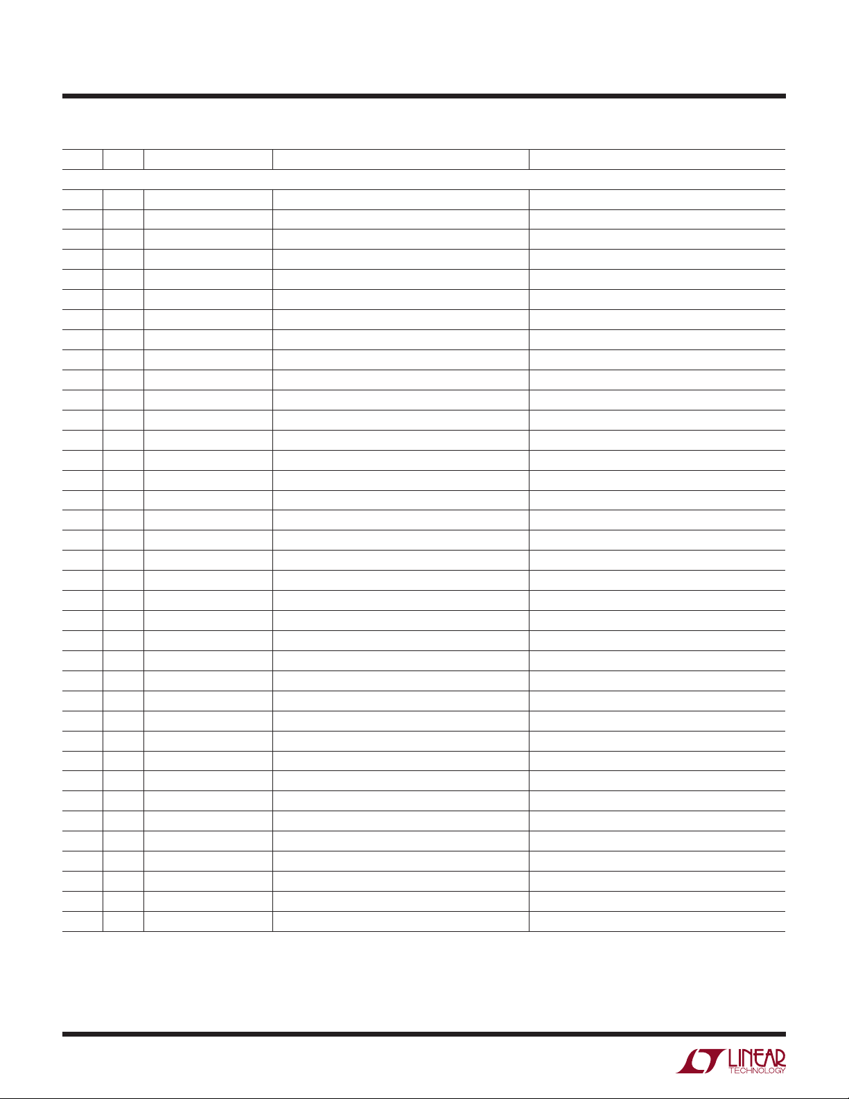
parts List
ITEM QTY REFERENCE PART DESCRIPTION MANUFACTURER/PART NUMBER
Required Circuit Components
1 1 CHG CAP., X7R, 10nF, 100V, 20%, 0805 AVX, 08051C103MAT2A
2 2 COUT1, COUT2 CAP., X7S, 10µF, 50V, 20%, 1210 TDK, C3225X7S1H106M
3 0 COUT3, COUT4 CAP., X7S, 10µF, 50V, 10%, 1210 OPT
4 1 COV CAP., X7R, 1nF, 100V, 20%, 0805 AVX, 08051C102MAT2A
5 1 CSNUB CAP., X5R, 10nF, 500V, 20%, 1812 AVX, 18127C103MAT2A
6 1 CTMR CAP., X5R, 4.7µF, 10V, 10%, 0805 TDK, C2012X5R1A475K
7 2 C1, CUV CAP., X7R, 100nF, 100V, 20%, 0805 AVX, 08051C104MAT2A
8 2 DLED1, DLED4 LED, GREEN J-TYPE, LED-LN1351C-GREEN PANASONIC, LN1351C-TR
9 2 DLED2, DLED5 LED, RED J-TYPE, LED-LN1251C-RED PANASONIC, LN1251C-TR
10 2 D2, DLED3 DIODE, 300V, 250mA, SOD523 DIODES/ZETEX, BAS521-7
11 1 D1 DIODE, ZENER, 68V, 1.5W, SMA-DIODE CENTRAL SEMI., CMZ5945B
12 1 D3 DIODE, RECTIFIER, 400V, 1.0A, SMA-DIODE DIODES INC., ES1G-13-F
13 1 D4 DIODE, TVS, 24V, 400W, SMA-DIODE DIODES INC., SMAJ24A-13-F
14 2 D6, D7 DIODE, DDZ9702S, 15V, 200mW, SOD323 DIODES INC., DDZ9702S-7
15 6 E2, E3, E4, E5, E6, E8 TESTPOINT, TURRET, 0.094 MILL-MAX, 2501-2-00-80-00-00-07-0
16 4 E10, E11, E12, E14 TESTPOINT, TURRET, 0.064 MILL-MAX, 2308-2-00-80-00-00-07-0
17 4 J1, J2, J3, J4 BANANA JACK, NON-INSULATED KEYSTONE, 575-4
18 1 M1 MOSFET, N-CH, 250V, D2-PAK FAIRCHILD, FDB33N25TM
19 1 M2 MOSFET, N-CH, PWR 100V, 7.5A, SO8 FAIRCHILD, FDS3672
20 1 QLED1 TRANSISTOR, NPN, 300V, SOT223 FAIRCHILD, PZTA42
21 1 QLED2 TRANSISTOR, NPN, 40V, SOT-23 DIODES/ZETEX, MMBT3904-7-F
22 0 Q1 TRANSISTOR, PZTA42, NPN, 300V, SOT223 OPT
23 1 RESR RES., SENSE, 0.1, 1/8W, 5%, 0805 NIC, NCST10JR100HTRF
24 3 RUV1, ROV1, RLED1 RES., CHIP, 249k, 1/4W, 1%, 1206 NIC, NRC12F2493TRF
25 1 RLED2 RES., CHIP, 200, 1/8W, 5%, 0805 NIC, NRC10J201TRF
26 2 RLED3, RLED4 RES., CHIP, 3.3k, 1/4W, 5%, 1206 NIC, NRC12J332TRF
27 2 ROV2, R8 RES., CHIP, 21k, 1/8W, 1%, 0805 NIC, NRC10F2102TRF
28 1 RSNS RES., SENSE, 0.02, 1/4W, 5% 1206 NIC, NCST12JR020JTRF
29 1 RSNUB RES., CHIP, 100, 1/2W, 5%, 1210 NIC, NRCP25J101TRF
30 1 RUV2 RES., CHIP, 66.5k, 1/8W, 1%, 0805 NIC, NRC10F6652TRF
31 1 RVCC RES., CHIP, 0, 0805 NIC, NRC10Z0TRF
32 1 R4 RES., CHIP, 2.2k, 1/4W, 5%, 1206 NIC, NRCP12J222TRF
33 1 R5 RES., CHIP, 10, 1/8W, 5%, 0805 NIC, NRC10J100TRF
34 1 R7 RES., CHIP, 453k, 1/8W, 1%, 0805 NIC, NRC10F4533TRF
35 4 MH1, MH2, MH3, MH4 STANDOFF, NYLON 0.5" KEYSTONE, 8833 (SNAP-ON)
36 1 U1 I.C., LTC4364HDE-1, DC2027A-A LINEAR TECHNOLOGY, LTC4364HDE-1
37 1 U1 I.C., LTC4364HDE-2, DC2027A-B LINEAR TECHNOLOGY, LTC4364HDE-2