LinMot E1400-GP-QN-xS User manual

E14x0 V1 Rev. E Servo Drives
Installation Guide
Eine Deutsche Version kann unter http://www.linmot.com bezogen werden!
Please visit http://www.linmot.com to check for the latest version of this document!
This document applies to the following drives:
E1400-GP-Q -xS E1430-DP-Q -xS
E1450-PL-Q -xS E1450-EC-Q -xS
E1450-SE-Q -xS E1450-P -Q -xS
E1450-IP-Q -xS E1450-SC-Q -xS
ATTENTION: The connectors have to be ordered separate y and are
not inc uded with the drive!
DC01-E1400/X4/X30 Drive Connector Set for E1400-0S 0150-3452
DC01-E1400/X4/X30/X33 Drive Connector Set for E1400-1S 0150-3453

E 400 V Rev. E Installation Guide
© 2013 TI AG
This work is protected by copyright.
Under the copyright laws, this publication may not be reproduced or transmitted in any form, electronic or mechanical, including
photocopying, recording, microfilm, storing in an information retrieval system, not even for didactical use, or translating, in whole or in
part, without the prior written consent of TI AG.
LinMot® is a registered trademark of TI AG.
The information in this documentation reflects the stage of development at the time of press and is therefore without obligation.
TI AG reserves itself the right to make changes at any time and without notice to reflect further technical advance or product
improvement.
Document version 6.0a / FM, December 2013
Page 2/23 www.LinMot.com NTI AG / LinMot®

E 400 V Rev. E Installation Guide
Tab e of Content
1 Important Safety Instructions.........................................................................................4
2 System Overview.............................................................................................................6
3 Functiona ity and Interfaces...........................................................................................7
4 IP Address Se ection.......................................................................................................7
5 Power Supp y and Grounding........................................................................................8
6 Description of the connectors / Interfaces....................................................................9
6.1 X1-V1 Rev. D/E...........................................................................................................9
6.2 X30-V1 Rev. D/E.........................................................................................................9
6.3 X2-V1 Rev. D/E...........................................................................................................9
6.4 X31-X32....................................................................................................................10
6.5 X3-V2........................................................................................................................10
6.6 X4 .............................................................................................................................10
6.7 X33 ...........................................................................................................................11
6.8 X7 - X8......................................................................................................................11
6.9 X9..............................................................................................................................11
6.10 X10 - X11................................................................................................................12
6.11 X13..........................................................................................................................12
6.12 X15 - X16................................................................................................................13
6.13 X17 - X18................................................................................................................13
6.14 X19..........................................................................................................................13
6.15 X20..........................................................................................................................14
6.16 X29..........................................................................................................................14
6.17 S5............................................................................................................................14
6.18 LEDs.......................................................................................................................15
6.19 RT BUS LEDs.........................................................................................................15
6.20 S1 - S2....................................................................................................................15
7 Error Codes....................................................................................................................16
8 Safety Wiring..................................................................................................................17
9 Physica Dimensions.....................................................................................................18
10 Power Supp y Requirements......................................................................................19
11 Regeneration of Power / Regeneration Resistor......................................................19
12 Ordering Information...................................................................................................20
13 Internationa Certifications.........................................................................................20
14 Dec aration of Conformity CE-Marking......................................................................21
15 Contact Addresses......................................................................................................22
NTI AG / LinMot®www.LinMot.com Page 3/23

E 400 V Rev. E Installation Guide
1 Important Safety Instructions
For your persona safety
Disregarding the following safety measures can lead to severe injury to persons and
damage to material:
•Only use the product as directed.
•ever commission the product in the event of visible damage.
•ever commission the product before assembly has been completed.
•Do not carry out any technical changes on the product.
•Only use the accessories approved for the product.
•Only use original spare parts from LinMot.
•Observe all regulations for the prevention of accidents, directives and laws applicable on site.
•Transport, installation, commissioning and maintenance work must only be carried out by qualified
personnel.
•Observe IEC 364 and CE ELEC HD 384 or DI VDE 0100 and IEC report 664 or
DI VDE 0110 and all national regulations for the prevention of accidents.
•According to the basic safety information, qualified, skilled personnel are persons who are
familiar with the assembly, installation, commissioning, and operation of the product and who
have the qualifications necessary for their occupation.
•Observe all specifications in this documentation.
•This is the condition for safe and trouble−free operation and the achievement of the specified
product features.
•The procedural notes and circuit details described in this documentation are only proposals.
It is up to the user to check whether they can be transferred to the particular applications.
TI AG / LinMot does not accept any liability for the suitability of the procedures and circuit
proposals described.
•LinMot servo drives and the accessory components can include live and moving parts (depending on
their type of protection) during operation. Surfaces can be hot.
•on−authorized removal of the required cover, inappropriate use, incorrect installation or
operation create the risk of severe injury to persons or damage to material assets.
•For more information, please see the documentation.
•High amounts of energy are produced in the drive. Therefore it is required to wear personal
protective equipment (body protection, headgear, eye protection, hand guard).
App ication as directed
•Drives are components which are designed for installation in electrical systems or machines. They
are not to be used as domestic appliances, but only for industrial purposes according to E
61000−3−2.
•When drives are installed into machines, commissioning (i.e. starting of the operation as directed) is
prohibited until it is proven that the machine complies with the regulations of the EC Directive
98/37/EC (Machinery Directive); E 60204 must be observed.
•Commissioning (i.e. starting of the operation as directed) is only allowed when there is compliance
with the EMC Directive (2004/108/EC).
•The technical data and supply conditions can be obtained from the nameplate and the
documentation. They must be strictly observed.
Transport, storage
•Please observe the notes on transport, storage, and appropriate handling.
•Observe the climatic conditions according to the technical data.
Page 4/23 www.LinMot.com NTI AG / LinMot®
E 400 V Rev. E Installation Guide
Insta ation
•The drives must be installed and cooled according to the instructions given in the corresponding
documentation.
•The ambient air must not exceed degree of pollution 2 according to E 61800−5−1.
•Ensure proper handling and avoid excessive mechanical stress. Do not bend any components and
do not change any insulation distances during transport or handling. Do not touch any electronic
components and contacts.
•drives contain electrostatic sensitive devices which can easily be damaged by inappropriate
handling. Do not damage or destroy any electrical components since this might endanger your
health!
E ectrica connection
•When working on live drives, observe the applicable national regulations for the prevention of
accidents.
•The electrical installation must be carried out according to the appropriate regulations (e.g. cable
cross−sections, fuses, PE connection). Additional information can be obtained from the
documentation.
•This product can cause high-frequency interferences in non industrial environments
which can require measures for interference suppression.
Operation
•If necessary, systems including drives must be equipped with additional monitoring and protection
devices according to the valid safety regulations (e.g. law on technical equipment, regulations for the
prevention of accidents). The drives can be adapted to your application. Please observe the
corresponding information given in the documentation.
•After the drive has been disconnected from the supply voltage, all live components and power
connections must not be touched immediately because capacitors can still be charged. Please
observe the corresponding stickers on the drive. All protection covers and doors must be shut during
operation.
Protection of persons
•Before working on the drive, check that no voltage is applied to the power terminals:
•The power terminals U, V, W, DC+, DC-, RR+, and RR- remain live for at
least 5 minutes after disconnecting from mains.
•The power terminals L1, L2, L3; U, V, W, KTY+, KTY-, DC+, DC-, RR+ and
RR- remain live when the motor is stopped.
•The leakage current to earth (PE) is >3.5 mA. According to E 50178 a fixed
installation is required and a double PE connection is required.
•The heat sink of the drive has an operating temperature of > 80 °C: Contact with the
heat sink results in burns.
NTI AG / LinMot®www.LinMot.com Page 5/23
E 400 V Rev. E Installation Guide
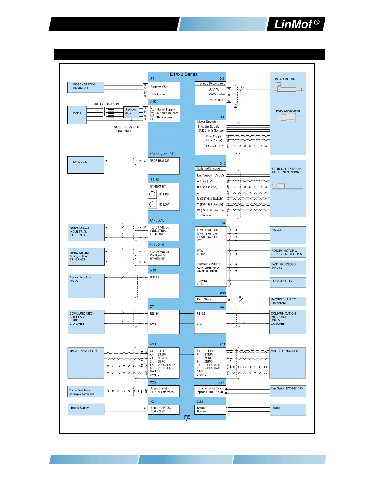
2 System Overview
Typical Servo System E14x0-XX: Servo Drive, Motor and Power Supply.
Page 6/23 www.LinMot.com NTI AG / LinMot®

E 400 V Rev. E Installation Guide
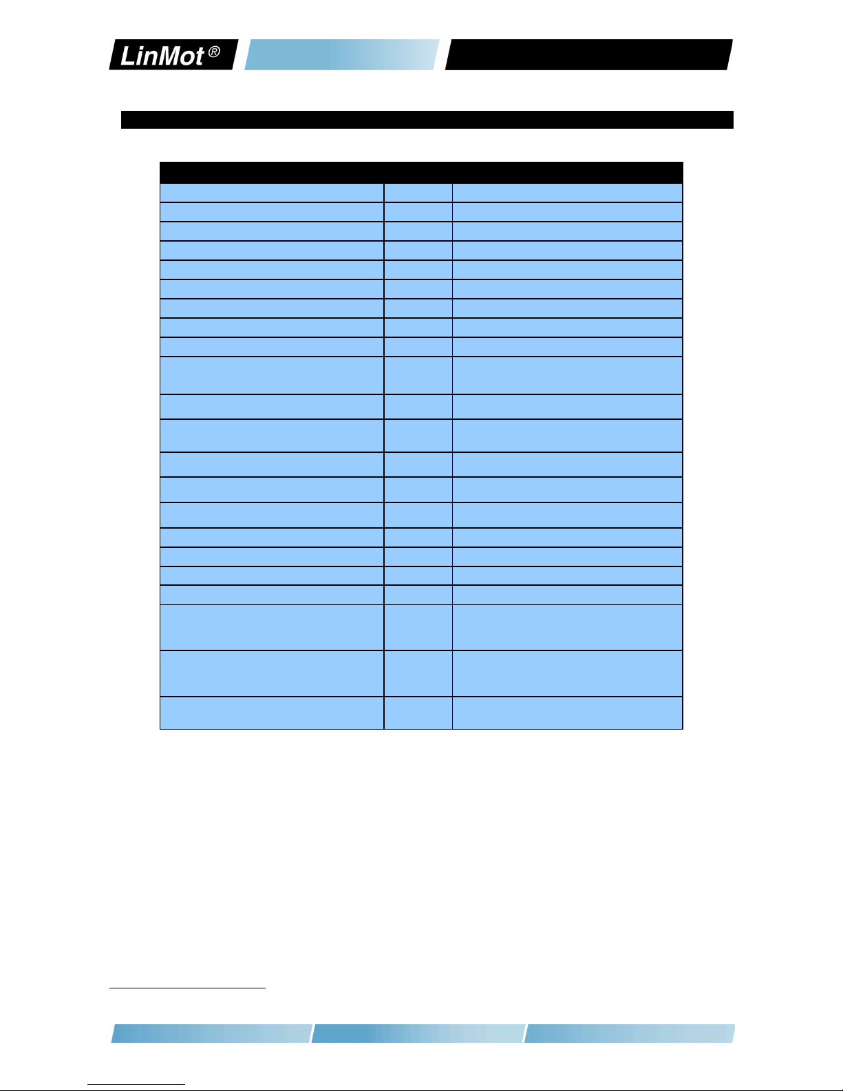
3 Functiona ity and Interfaces
E1450-PL-QN-0S
E1450-PN-QN-0S
E1450-SC-QN-0S
E1450-IP-QN-0S
E1450-EC-QN-0S
E1430-DP-QN-0S
E1450-GP-QN-0S
E1450-PL-QN-1S
E1450-PN-QN-1S
E1450-SC-QN-1S
E1450-IP-QN-1S
E1450-EC-QN-1S
E1430-DP-QN-1S
E1400-GP-QN-1S
Supp y Vo tage
Motor Supply 3x400 VAC / 3x480 VAC ● ● ● ● ● ● ● ● ● ● ● ● ● ●
Logic Supply 24VDC (22...26VDC) ● ● ● ● ● ● ● ● ● ● ● ● ● ●
Motor Phase Current (pre iminary)
28A rms peak ●●●●●●●●●●●●●●
4 A rms continuous (without forced cooling) ● ● ● ● ● ● ● ● ● ● ● ● ● ●
12 A rms continuous (with fan option EV01-E1400) ● ● ● ● ● ● ● ● ● ● ● ● ● ●
18 A rms continuous (cold plate 20°C) ● ● ● ● ● ● ● ● ● ● ● ● ● ●
Contro ab e Motors
LinMot P10-70x…(Motor Link C) ● ● ● ● ● ● ● ● ● ● ● ● ● ●
Selected motors (contact support) ● ● ● ● ● ● ● ● ● ● ● ● ● ●
Command Interface
CAopen ●●●●●●●●●●●●●●
LinRS ●●●●●●●●●●●●●●
POWERLI K ● ●
PROFI ET ● ●
SERCOS III ● ●
ETHER ET IP ● ●
LinUDP ● ●
ETHERCAT ● ●
PROFIBUS-DP ● ●
Programmab e Motion Profi es (Curves)
Up to 100 Motion Profiles ● ● ● ● ● ● ● ● ● ● ● ● ● ●
Programmab e Command Tab e
Command Table with up to 255 entries ● ● ● ● ● ● ● ● ● ● ● ● ● ●
Externa Position Sensor
Incremental (RS422 up to 25 M counts/s) ● ● ● ● ● ● ● ● ● ● ● ● ● ●
SinCos (1Vpp differential) ● ● ● ● ● ● ● ● ● ● ● ● ● ●
Absolute (BiSS) ● ● ● ● ● ● ● ● ● ● ● ● ● ●
Synchronisation
Master Encoder In/Out
(RS422 up to 25 M counts/s) ●●●●●●●●●●●●●●
Configuration Interface
RS232 ●●●●●●●●●●●●●●
Ethernet 10/100 Mbit/s
(2-Port Switch integrated) ●●●●●●●●●●●●●●
Integrated Safety Functions (-1S Option)
STO (2 Safety Relays) ● ● ● ● ● ● ●
4 IP Address Se ection
The default mode for acquiring an IP address is via DHCP. If no servers respond on
the connected network, the drive switches to the IPv4 Link-Local addressing
scheme (also known as APIPA on Windows systems). This way the drive
automatically assigns itself an address within the range of 169.254.0.1 through
169.254.255.254 (Subnet Mask 255.255.0.0).
Please note that this process can take up to a minute until a valid address is
assigned to the drive.
NTI AG / LinMot®www.LinMot.com Page 7/23
E 400 V Rev. E Installation Guide
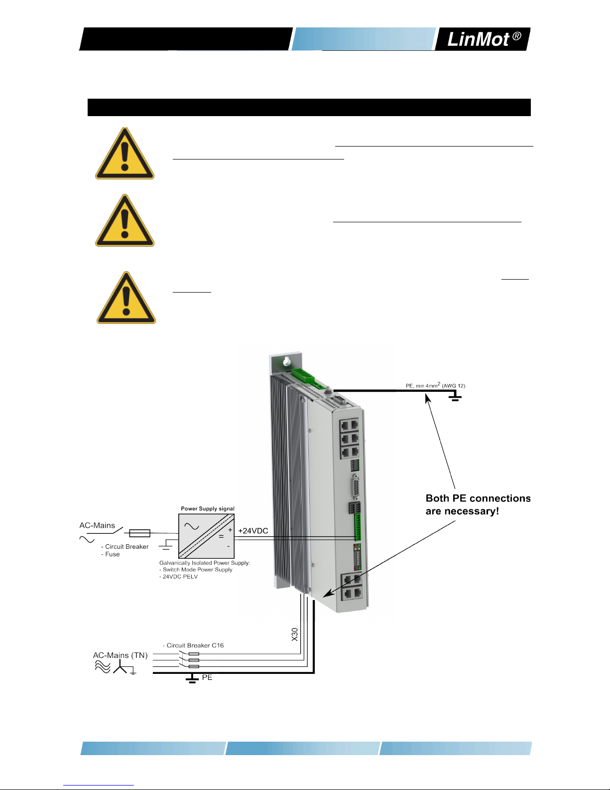
5 Power Supp y and Grounding
In order to assure a safe and error free operation, and to avoid severe
damage to system components, a system components must be we
grounded to protective earth PE. This includes both LinMot and all
other control system components on the same ground bus.
The leakage current to earth (PE) is >3.5 mA. According to E 50178 a
fixed installation is required and a doub e PE connection is required.
One PE connection is on X30, the second one is an M5 bolt on top of
the housing.
Each system component should be tied directly to the ground bus (star
pattern), rather than daisy chaining from component to component.
(LinMot motors are properly grounded through their power cables when
connected to LinMot drives.)
Page 8/23 www.LinMot.com NTI AG / LinMot®
E 400 V Rev. E Installation Guide
6 Description of the connectors / Interfaces
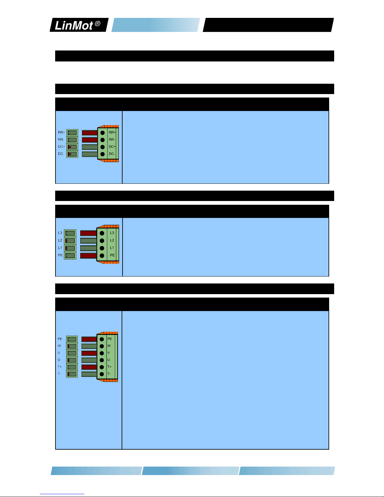
6.1 X1-V1 Rev. D/E
X1 DC Busbar/ Regeneration Resistor
RR+: Positive connection for Regeneration Resistor
RR-: egative connection for Regeneration Resistor
DC+: DC busbar +
DC-: DC busbar -
Screw Terminals:
- Tightening torque: 0.7 - 0.8 m
- Use a cross-head screw driver (PH1)
- Use 60/75°C copper conductors only
- Conductor cross-section: 0.25 – 4 mm2 (depends on Motor current) / AWG 24 -12
- Stripping length 10mm
6.2 X30-V1 Rev. D/E
X30 Motor Supp y Mains
L1 – L3: 3x400 / 3x480VAC 50/60 Hz
PE: PE, Protective Earth
Screw Terminals:
- Tightening torque: 0.7 - 0.8 m
- Use a cross-head screw driver (PH1)
- Use 60/75°C copper conductors only
- Conductor cross-section: 2.5 – 4 mm2 (depends on Motor current) / AWG 24 -12
- Stripping length 10mm
6.3 X2-V1 Rev. D/E
X2 Motor Phases
PE: Protective Earth and Cable Shield
W: Motor Phase W
V: Motor Phase V
U: Motor Phase U
T+: Temperature Sensor KTY+ (on DC- voltage level!)
T-: Temperature Sensor KTY- (on DC- voltage level!)
Attention:
KTY+ and KTY- are not referenced to ground! They are on DC- vo tage!
An iso ated thermistor is necessary! Especia y LinMot D01 and D02
Motors can not be connected!
Screw Terminals:
- Tightening torque: 0.7 - 0.8 m
- Use a cross-head screw driver (PH1)
- Use 60/75°C copper conductors only
- Conductor cross-section: 0.25 – 4 mm2 (depends on Motor current) / AWG 24 -12
- Stripping length 10mm
Attention:
The type of connector and pin assignment on V1 Rev. D and V2 drives
is different from V1 (Rev. A-C) drives (different coding)!
NTI AG / LinMot®www.LinMot.com Page 9/23
E 400 V Rev. E Installation Guide
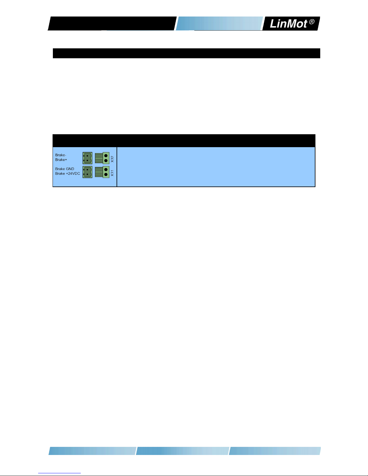
6.4 X31-X32
X31-X32 Motor Brake and Motor Brake Supp y
X32: Brake-
Brake+
X31: Brake Supply G D
Brake Supply +24VDC
Page 0/23 www.LinMot.com NTI AG / LinMot®
E 400 V Rev. E Installation Guide
6.5 X3-V2
X3 Motor Encoder (Motor Link C / BISS)
8
15
7
14
6
13
5
12
4
11
3
10
2
9
1
case
Motor Link C -
Motor Link C +
Clock -
Clock +
Data -
Data +
G D
do not connect
G D Sense
+5V Sense
Cos-
Cos+
Sin-
Sin+
+5V
shield
DSUB-15 (m) Motor Link C is a high speed serial communication protocol to the motor encoder.
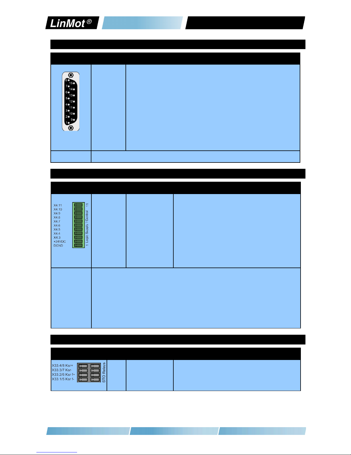
6.6 X4
X4 Logig Supp y / IO Connection
11
10
9
8
7
6
5
4
3
2
1
Input Quickstop
I/O X4.10
I/O X4.9
I/O X4.8
I/O X4.7
I/O X4.6
I/O X4.5
I/O X4.4
I/O X4.3
+24VDC Supply
G D Supply
Quickstop, PTC2 Input
Configurable IO, PTC1 Input
Configurable IO
Configurable IO
Configurable IO, Analog Input for EasySteps Application
Configurable IO, Trigger Input
Configurable IO
Configurable IO, Analog Input (configurable as high imp. Input)
Configurable IO
Logic Supply 22-26 VDC
Ground
Spring cage
connector
Inputs (X4.3 .. X4.11): 24V / 5mA (Low Level: –0.5 to 5VDC, High Level: 15 to 30VDC)
Outputs (X4.3 .. X4.10): 24V / max.100mA, Peak 370mA (will shut down if exceeded)
Supply 24V / type. 500mA / max. 2.5A (if all outputs “on” with max. load.)
- Use 60/75°C copper conductors only
- Conductor cross-section max. 1.5mm2
- Stripping length: 10mm
- Internal Fuse (F2): 3AT (slow blow, Schurter OMT125, 3404.0118.xx, UL File umber: E41599)
CAUTIO : For continued protection against risk of fire, replace only with same type and rating of fuse.
6.7 X33
X33 Safety Re ays (on y with the -1S option)
4 / 8
3 / 7
2 / 6
1 / 5
Ksr +
Ksr -
Ksr f+
Ksr f-
Safety Relay 1 / 2 Input positive
Safety Relay 1 / 2 Input negative
Safety Relay 1 / 2 feedback positive
Safety Relay 1 / 2 feedback negative
NTI AG / LinMot®www.LinMot.com Page /23

E 400 V Rev. E Installation Guide
Spring cage connector - Use 60/75°C copper conductors only
- Conductor cross-section max. 1.5mm2
- Stripping length: 10mm
- ever connect the safety relays to the logic supply of the drive!
6.8 X7 - X8
X7 - X8 CMD (RS485/CAN)
1
2
X3
4
5
6
7
8
case
RS485_Rx+ A
RS485_Rx- B
RS485_Tx+ Y
G D
G D
RS485_Tx- Z
CA _H
CA _L
Shield
RJ-45 Use twisted pair (1-2, 3-6, 4-5, 7-8) cable for wiring.
The built in RS485 and CA terminations can be activated by S5.2 and S5.3.
X7 is internally connected to X8 (1:1 connection)
6.9 X9
X9 PROFIBUS DP (on y avai ab e on E1430-DP-QN)
1
6
2
7
3
8
4
9
5
case
ot connected
+5V (isolated)
ot connected
ot connected
RxD/TxD-P
RxD/TxD-
C TR-P
ot connected
G D (isolated)
Shield
DSUB-9 (f) Max. Baud rate: 12Mbaud
Page 2/23 www.LinMot.com NTI AG / LinMot®

E 400 V Rev. E Installation Guide
6.10 X10 - X11
X10 - X11 Master Encoder IN (X10) / Master Encoder OUT (X11)
1
2
3
4
5
6
7
8
case
Incremental: Step/Direction:
A+ Step+
A- Step-
B+ Direction+
Z+ Zero+
Z- Zero-
B- Direction-
CA _H CA _H
CA _L CA _L
Shield Shield
EIA/TIA 568A colors:
Green/White
Green
Orange/White
Blue
Blue/White
Orange
Brown/White
Brown
RJ-45 Use twisted pair (1-2, 3-6, 4-5, 7-8) cable for wiring.
Master Encoder Inputs: Differential RS422, max. 25 M counts/s, 40ns edge separation
Master Encoder Outputs: Amplified RS422 differential signals from Master Encoder I (X10)
The CA bus can be terminated with S5.4.
All devices, which are connected to X10/X11 must be referenced to the same ground.
6.11 X13
X13 Externa Position Sensor Differentia Ha Switches
1
9
2
10
3
11
4
12
5
13
6
14
7
15
8
case
+5V DC
A+
A-
B+
B-
Z+
Z-
Encoder Alarm
G D
U+
U-
V+
V-
W+
W-
Shield
DSUB-15 (f) Position Encoder Inputs (RS422):
Max Input Frequency: 25 M counts/s with quadrature decoding, 40ns edge separation
Encoder Simulation Outputs (RS422):
Max Output Frequency: 25 M counts/s with quadrature decoding, 40ns edge separation
Differential Hall Switch Inputs (RS422):
Input Frequency: <1kHz
Enc. Alarm In:
5V / 1mA
Sensor Supply:
5VDC max. 100mA / 9VDC 100mA (SW selectable)
NTI AG / LinMot®www.LinMot.com Page 3/23
E 400 V Rev. E Installation Guide
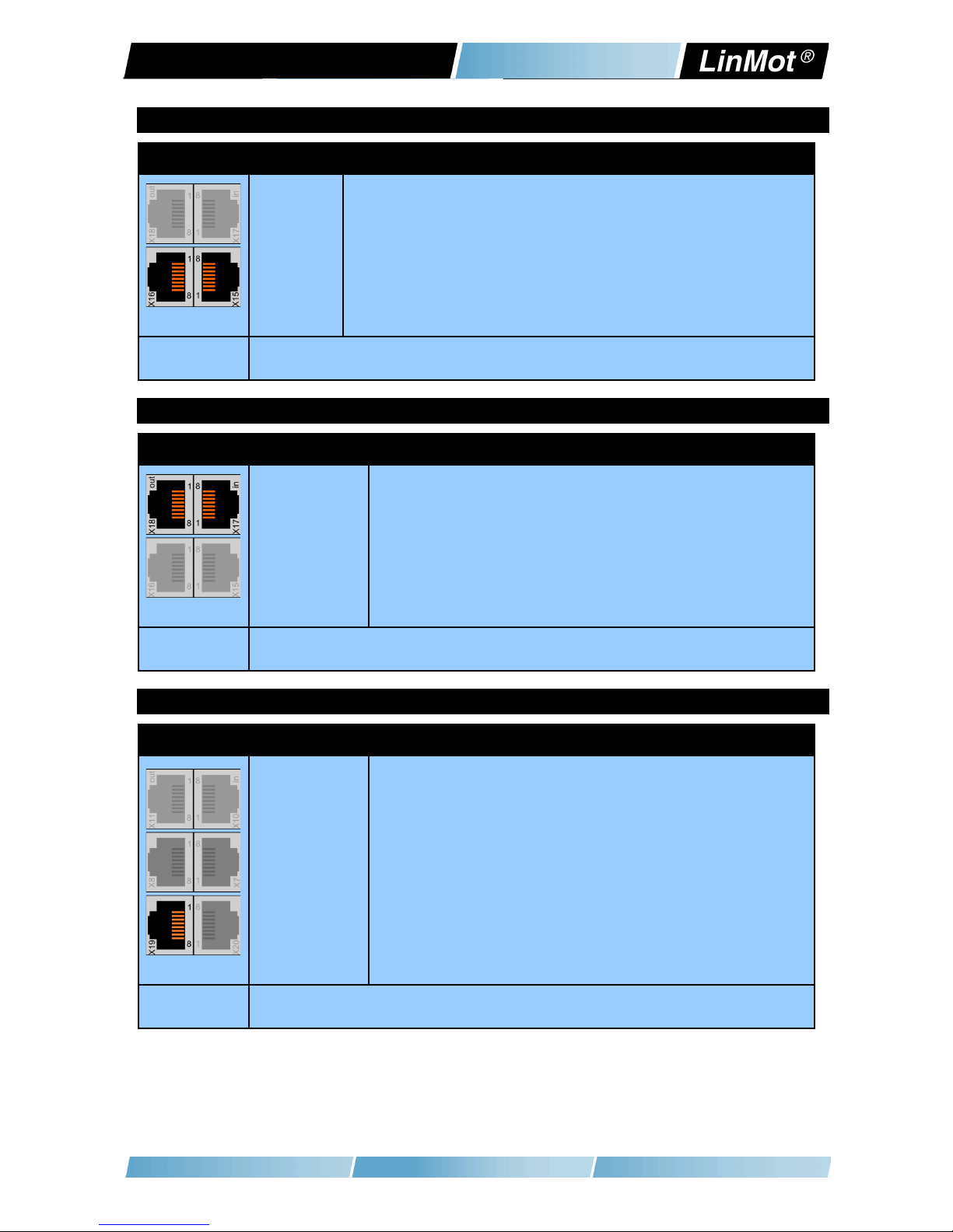
6.12 X15 - X16
X15 - X16 Config Ethernet 10/100 Mbit/s
X15
X16
Internal 2-Port 10BASE-T and 100BASE-TX Ethernet Switch with Auto MDIX.
LEDs on the lower side of the device indicate “Link/Activity” per port, the upper ones
are not used.
RJ-45
6.13 X17 - X18
X17 - X18 Rea Time Ethernet 10/100 Mbit/s
X17 RT ETH In
X18 RT ETH Out
Specification depends on RT-Bus Type. Please refer to according documentation.
RJ-45
6.14 X19
X19 System
1
2
3
4
5
6
7
8
case
Do not connect
Do not connect
RS232 Rx
G D
G D
RS232 Tx
Do not connect
Do not connect
Shield
RJ-45 Use adapter cable AC01-RJ45/Df-2.5-RS1 (Art.-No. 0150-2143) for configuration over RS232.
Page 4/23 www.LinMot.com NTI AG / LinMot®

E 400 V Rev. E Installation Guide
6.15 X20
X20 Ana og In (+-10V Differentia Ana og Input)
1
2
3
4
5
6
7
8
case
Do not connect
Do not connect
Analog In -
G D
G D
Analog In +
Do not connect
Do not connect
Shield
RJ-45
6.16 X29
X29 Connector for Fan Option
Connector for the external fan option (Art. r. 0150-xxxx).
Output: 24 VDC / 0.4 A (Short circuit protected, current monitored)
Stripping length: 8mm
Conductor cross section: 0.2 – 1.5 mm2 (AWG 24 - 16)
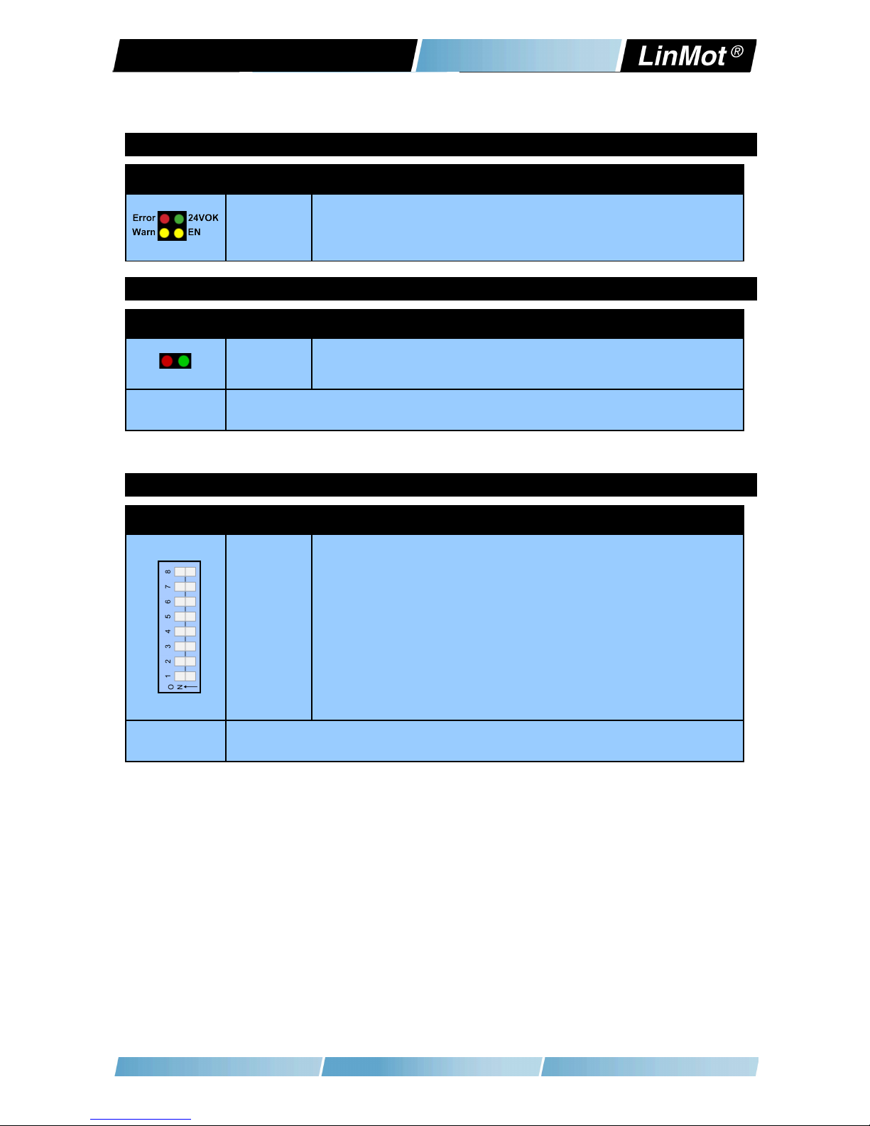
6.17 S5
S5 Bus Termination / AnaIn2 Pu Down
S5 Switch 6: Override Configuration Ethernet to DHCP
Switch 5: Bootstrap: Must be off for normal operation
Switch 4: CA termination on ME (120R between pin 7 and 8 on X10/X11) on/off
Switch 3: CA termination on CMD (120R between pin 7 and 8 on X7/X8) on/off
Switch 2: Termination resistor for RS485 on CMD (120R between pin 1 and 2 on X7/X8) on/off
Switch 1: AnIn2 pull down (4k7 Pull down on X4.4). Set to O , if X4.4 is used as digital output.
Factory setting: all switches “on” except S5.5 (Bootstrap) and S5.6 (Override to DHCP)
NTI AG / LinMot®www.LinMot.com Page 5/23
E 400 V Rev. E Installation Guide
6.18 LEDs
LEDs State Disp ay
Green
Yellow
Yellow
Red
24V Logic Supply OK
Motor Enabled / Error Code Low ibble
Warning / Error Code High ibble
Error
6.19 RT BUS LEDs
RT Bus LEDs RT Bus State Disp ay
Green
Red
OK
Error
The use of these LEDs depends on the type of fieldbus which is used. Please see the corresponding
manual for further information.
6.20 S1 - S2
S1 - S2 Address Se ectors
S1 (5..8)
S2 (1..4)
Bus ID High (0 … F). Bit 5 is the LSB, bit 8 the MSB.
Bus ID Low (0 … F). Bit 1 is the LSB, bit 4 the MSB.
The use of these switches depends on the type of fieldbus which is used. Please see the corresponding
manual for further information.
Page 6/23 www.LinMot.com NTI AG / LinMot®

E 400 V Rev. E Installation Guide
7 Error Codes
Error Codes
Error Warn EN Description
Off Warning Operation
Enabled
Norma Operation:
Warnings and operation enabled are displayed.
On ● ~2Hz
0..15 x
Error Code
High ibble
● ~2Hz
0..15 x
Error Code
Low ibble
Error:
The error code is shown by a blink code with “WAR ” and “E ”.
The error byte is divided into low and high nibble (= 4 bit).
”WAR ” and “E ” are blinking together.
The error can be acknowledged.
(e.g.: WAR blinks 3x, E blinks 2x; Error Code = 32h)
● ~2Hz ● ~2Hz
0..15 x
Error Code
High ibble
● ~2Hz
0..15 x
Error Code
Low ibble
Fata Error:
The error code is shown by a blink code with “WAR ” and “E ”.
The error byte is divided into low and high nibble.
”WAR ” and “E ” are blinking together.
Fatal errors can only be acknowledged by a reset or power cycle.
(e.g.: WAR blinks 3x, E blinks 2x; Error Code = 32h)
● ~4Hz ● ~2Hz
0..15 x
Error Code
High ibble
● ~2Hz
0..15 x
Error Code
Low ibble
System Error:
Please reinstall firmware or contact support.
● ~0.5Hz ● ~0.5Hz On Signa Supp y 24V too ow:
The error and warn LEDs blink alternating if the signal supply +24V (X4.2) is
less than 18VDC.
Off M●●● ●M●● P ug&P ay Communication Active
This sequence (Warn on, then En on, then both off, complete sequence of the
4 states ca. 1Sec) signalizes the state when the plug and play parameters are
being read from the motor.
The meaning of the error codes can be found in the
Usermanual_MotionCtrl_Software_SG5 and the user manual of the installed
interface software. These documents are provided together with LinMot-Talk
configuration software and can be downloaded from www.linmot.com.
NTI AG / LinMot®www.LinMot.com Page 7/23
E 400 V Rev. E Installation Guide
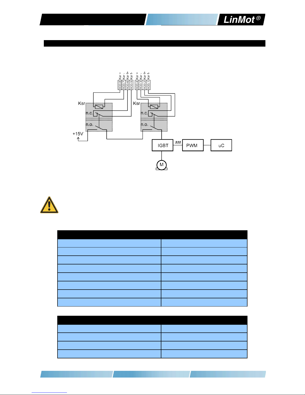
8 Safety Wiring
The E1400 Drive with the -1S option has internal safety functions:
Two Safety relays Ksr in series, which support the supply voltage for the motor
drivers. There are also two feedback contacts for each relay.
To enable the -1S drives both relays have to be switched on.
Minimal wiring:
- Connect X33.8 and X33.4 to 24VDC (from safety)
- Connect X33.7 and X33.3 to G D (from safety)
Attention: Never connect X33.8 and X33.4 to the ogic supp y of X4!
If an overvoltage protection is needed, it must be provided externally and
sized according the safety circuit of the machine!
Attention: The drop out time of the relays is depending on the external circuitry!
Safety Re ay Ksr
ominal voltage 24 VDC
Min. pick-up voltage at 20°C ≤ 16.8V
Drop-out voltage at 20°C ≥ 2.4 V
Drop-out time (no protection circuit) Typ. 3ms
Coil resistance at 20°C 2'100 Ω ± 10%
Type E 50205, type A
Contact lifetime > 10'000'000
Manufacturer and type Elesta relays / SIS112 24VDC
Drive C assification according EN ISO 13849-1 (safety of machinery)
Category cat = 3
Performance Level PL = d
Diagnostic Coverage DC = high
Mean Time to hazardous failure of one channel MTTFd = high
Page 8/23 www.LinMot.com NTI AG / LinMot®
E 400 V Rev. E Installation Guide
9 Physica Dimensions
E 400 Series single axis drive
Width mm (in) 50 (2)
Height mm (in) 300 (11.8)
Height with fixings mm (in) 345 (13.6)
Depth mm (in) 221.5 (8.8)
Weight kg (lb) 4.3 (9.5)
Mounting 2 x M5
Case IP 20
Storage Temperature °C -25…40
Transport Temperature °C -25…70
Operating Temperature °C 0…40 at rated data
40...50 with power derating
Relative humidity 95% (non-condensing)
Pollution IEC/E
60664-1
Pollution degree 2
Site altitude m amsl to be defined
Shock resistance (16ms) -1S option 3.5g
Vibration resistance (10-200Hz) -1S option 1g
Max. Case Temperature °C 90
Max. Power Dissipation W 100
Mounting place In the control cabinet
Mounting position vertical1
Distance between drives
(passive convection cooling)
mm (in) ≥ 35 (1.4) left (heat sink side)
≥ 5 (0.2) right
≥ 200 (8) top / bottom
Distance between drives (with fan option
EV01-E1400)
mm (in) ≥ 40 (1.6) left (heat sink side)
≥ 5 (0.2) right
≥ 200 (8) top / bottom
Distance between drives (cold plate
cooling)
mm (in) ≥ 0 (0) left/right
≥ 200 (8) top / bottom
1 Drive can be mounted upside down (motor connector on bottom side)
NTI AG / LinMot®www.LinMot.com Page 9/23
E 400 V Rev. E Installation Guide
10 Power Supp y Requirements
Motor Power Supp y
Direct AC mains connection: 3/PE AC 400V (±10%) / 50-60Hz / T System
3/PE AC 480V (±10%) / 50-60Hz / T System
On y 3-phase supp y is supported! The mains must be a symmetrica
four-wire system with grounded neutra .
DC Supp y (for examp e 72VDC) for initia test setups can be supp ied through
the 3-phase supp y connector.
Use a circuit breaker C16 and conductor cross section of 2.5mm2 for mains
connections!
The LinMot ine fi ter NF01-FN258-16-07 must be connected near the supp y
connector of the drive to conform to the EMC requirements of CE.
Current consumption:
Startup Current: Soft start over 50 Ohm charge resistor.
Signa Power Supp y
The logic supply needs a regulated power supply of a nominal voltage of 24 VDC.
The voltage must be between 22 and 26 VDC.
Current consumption:
min. 0.5A (no load on the outputs)
typ. 1.5A (all 10 outputs “on” with 100mA load and /Break with no load)
max. 2.5A (all 10 outputs “on” with 100mA load and /Break with 1A load)
Do not connect the safety relays to the 24VDC Signal Supply!
Use a separate power supply for the safety circuit!
11 Regeneration of Power / Regeneration Resistor
There are two possibilities to deal with power regeneration:
Option A: DC Link coupling or additional Capacitors
Option B: Install a regeneration resistor to X1 (RR+ and RR-). The threshold
value of the voltage depends on the used motor voltage power supply.
The max. threshold value must not exceed 780 VDC.
Item Description Art. No.
Regeneration Resistor RR01-68/100 (68 Ohm, 100 W) 0150-3373
Page 20/23 www.LinMot.com NTI AG / LinMot®
This manual suits for next models
7
Table of contents
Other LinMot Amplifier manuals


