LinMot C1200 User manual

C1200 Servo Drives
Installation Guide
Eine Deutsche Version kann unter http://www.linmot.com bezogen werden!
Please visit http://www.linmot.com to check for the latest version of this document!
This document applies to the following drives:
C1250-P -XC-xS C1250-EC-XC-xS
C1250-SE-XC-xS C1250-PN-XC-xS
C1250-IP-XC-xS C1250-SC-XC-xS
ATTENTION: The connectors have to be ordered separately and are
not included ith the drive!
DC01-C1200/X4/X30 Drive Connector Set for C1200-0S 0150-????
DC01-C1200/X4/X30/X33 Drive Connector Set for C1200-1S 0150-????

1200 Installation Guide Preliminary
© 2013 NTI AG
This work is protected by copyright.
Under the copyright laws, this publication may not be reproduced or transmitted in any form, electronic or mechanical, including
photocopying, recording, microfilm, storing in an information retrieval system, not even for didactical use, or translating, in whole or in
part, without the prior written consent of NTI AG.
inMot® is a registered trademark of NTI AG.
The information in this documentation reflects the stage of development at the time of press and is therefore without obligation.
NTI AG reserves itself the right to make changes at any time and without notice to reflect further technical advance or product
improvement.
Document version 5.2a / FM, June 2013
Page 2/22 www.LinMot.com NTI AG / LinMot®

Preliminary 1200 Installation Guide
Table of Content
1 Important Safety Instructions.........................................................................................4
2 System Overvie .............................................................................................................6
3 Interfaces..........................................................................................................................7
4 Functionality and Interfaces...........................................................................................8
5 Soft are............................................................................................................................8
6 Po er Supply and Grounding........................................................................................9
7 Description of the connectors / Interfaces..................................................................10
7.1 X1..............................................................................................................................10
7.2 X2..............................................................................................................................10
7.3 X3..............................................................................................................................11
7.4 X4 .............................................................................................................................12
7.5 X9..............................................................................................................................12
7.6 X13............................................................................................................................13
7.7 X17 - X18..................................................................................................................13
7.8 X19............................................................................................................................14
7.9 X33 ...........................................................................................................................14
7.10 S1 - S2....................................................................................................................14
7.11 S5............................................................................................................................15
7.12 EDs.......................................................................................................................15
7.13 RT BUS EDs.........................................................................................................15
8 Error Codes....................................................................................................................16
9 Safety Wiring..................................................................................................................17
10 Physical Dimensions...................................................................................................18
11 Po er Supply Requirements......................................................................................19
12 Regeneration of Po er................................................................................................19
13 Ordering Information...................................................................................................20
14 International Certifications.........................................................................................20
15 Declaration of Conformity CE-Marking......................................................................21
16 Contact Addresses......................................................................................................22
NTI AG / LinMot®www.LinMot.com Page 3/22

1200 Installation Guide Preliminary
1 Important Safety Instructions
For your personal safety
Disregarding the following safety measures can lead to severe injury to persons and
damage to material:
•Only use the product as directed.
•Never commission the product in the event of visible damage.
•Never commission the product before assembly has been completed.
•Do not carry out any technical changes on the product.
•Only use the accessories approved for the product.
•Only use original spare parts from inMot.
•Observe all regulations for the prevention of accidents, directives and laws applicable on site.
•Transport, installation, commissioning and maintenance work must only be carried out by qualified
personnel.
•Observe IEC 364 and CENE EC HD 384 or DIN VDE 0100 and IEC report 664 or
DIN VDE 0110 and all national regulations for the prevention of accidents.
•According to the basic safety information, qualified, skilled personnel are persons who are
familiar with the assembly, installation, commissioning, and operation of the product and who
have the qualifications necessary for their occupation.
•Observe all specifications in this documentation.
•This is the condition for safe and trouble−free operation and the achievement of the specified
product features.
•The procedural notes and circuit details described in this documentation are only proposals.
It is up to the user to check whether they can be transferred to the particular applications.
NTI AG / inMot does not accept any liability for the suitability of the procedures and circuit
proposals described.
•inMot servo drives and the accessory components can include live and moving parts (depending on
their type of protection) during operation. Surfaces can be hot.
•Non−authorized removal of the required cover, inappropriate use, incorrect installation or
operation create the risk of severe injury to persons or damage to material assets.
•For more information, please see the documentation.
•High amounts of energy are produced in the drive. Therefore it is required to wear personal
protective equipment (body protection, headgear, eye protection, hand guard).
Application as directed
•drives are components which are designed for installation in electrical systems or machines. They
are not to be used as domestic appliances, but only for industrial purposes according to EN
61000−3−2.
•When drives are installed into machines, commissioning (i.e. starting of the operation as directed) is
prohibited until it is proven that the machine complies with the regulations of the EC Directive
98/37/EC (Machinery Directive); EN 60204 must be observed.
•Commissioning (i.e. starting of the operation as directed) is only allowed when there is compliance
with the EMC Directive (2004/108/EC).
•The technical data and supply conditions can be obtained from the nameplate and the
documentation. They must be strictly observed.
Transport, storage
•Please observe the notes on transport, storage, and appropriate handling.
•Observe the climatic conditions according to the technical data.
Page 4/22 www.LinMot.com NTI AG / LinMot®

Preliminary 1200 Installation Guide
Installation
•The drives must be installed and cooled according to the instructions given in the corresponding
documentation.
•The ambient air must not exceed degree of pollution 2 according to EN 61800−5−1.
•Ensure proper handling and avoid excessive mechanical stress. Do not bend any components and
do not change any insulation distances during transport or handling. Do not touch any electronic
components and contacts.
•drives contain electrostatic sensitive devices which can easily be damaged by inappropriate
handling. Do not damage or destroy any electrical components since this might endanger your
health!
Electrical connection
•When working on live drives, observe the applicable national regulations for the prevention of
accidents.
•The electrical installation must be carried out according to the appropriate regulations (e.g. cable
cross−sections, fuses, PE connection). Additional information can be obtained from the
documentation.
•This product can cause high-frequency interferences in non industrial environments
which can require measures for interference suppression.
Operation
•If necessary, systems including drives must be equipped with additional monitoring and protection
devices according to the valid safety regulations (e.g. law on technical equipment, regulations for the
prevention of accidents). The drives can be adapted to your application. Please observe the
corresponding information given in the documentation.
•After the drive has been disconnected from the supply voltage, all live components and power
connections must not be touched immediately because capacitors can still be charged. Please
observe the corresponding stickers on the drive. All protection covers and doors must be shut during
operation.
Protection of persons
•Before working on the drive, check that no voltage is applied to the power terminals:
•The power terminals Ph1+, Ph1-, Ph2+, Ph2- and PWR+ remain live for at
least 5 minutes after disconnecting from the power supplies.
•The heat sink of the drive has an operating temperature of > 80 °C: Contact with the
heat sink results in burns.
NTI AG / LinMot®www.LinMot.com Page 5/22

1200 Installation Guide Preliminary
2 System Overvie
Typical Servo System C12x0-XX: Servo Drive, Motor and Power Supply.
Page 6/22 www.LinMot.com NTI AG / LinMot®

Preliminary 1200 Installation Guide
3 Interfaces
C12x0-xx-xx-xS-xxx
NTI AG / LinMot®www.LinMot.com Page 7/22
1200 Installation Guide Preliminary
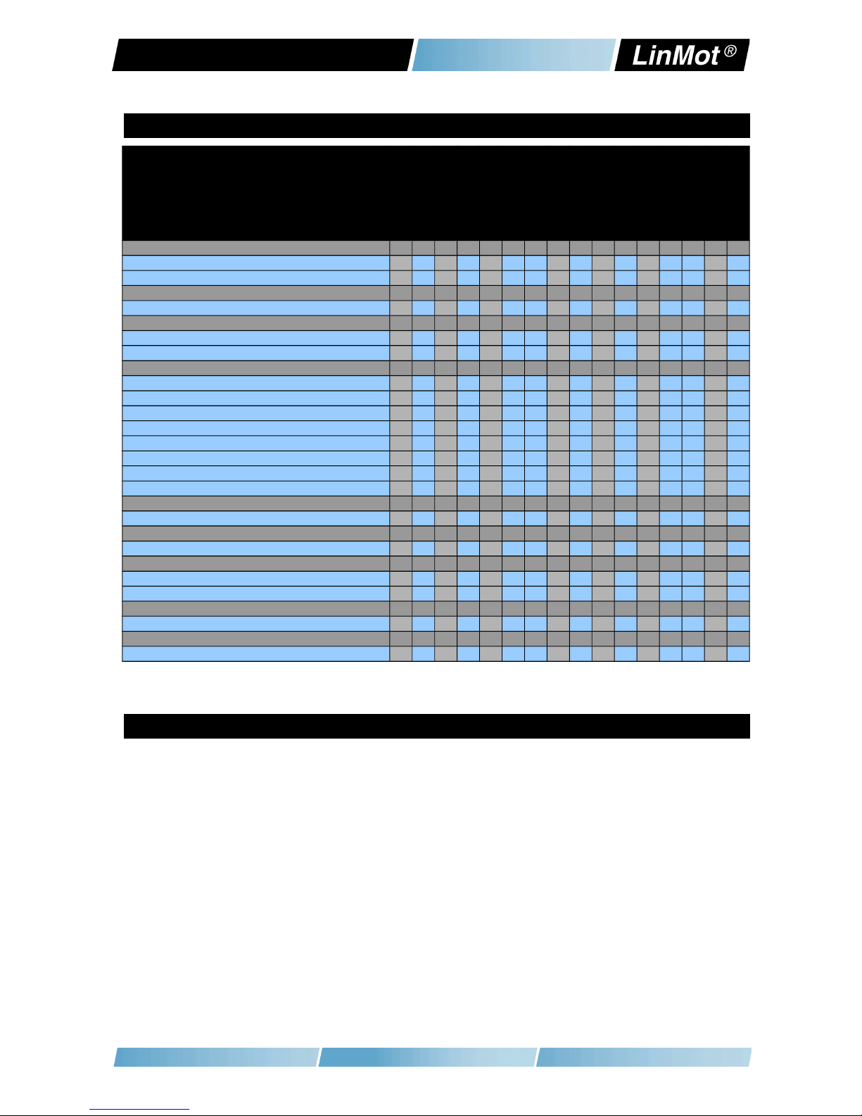
4 Functionality and Interfaces
C1250-PL-XC-0S
C1250-PN-XC-0S
C1250-SC-XC-0S
C1250-IP-XC-0S
C1250-EC-XC-0S
C1250-SE-XC-0S
C1230-DP-XC-0S
C1200-GP-XC-0S
C1250-PL-XC-1S
C1250-PN-XC-1S
C1250-SC-XC-1S
C1250-IP-XC-1S
C1250-EC-XC-1S
C1250-SE-XC-1S
C1230-DP-XC-1S
C1200-GP-XC-1S
Supply Voltage
Motor Supply 72VDC (24..85VDC) ● ● ● ● ● ● ● ● ● ● ● ● ● ● ● ●
ogic Supply 24VDC (22...26VDC) ● ● ● ● ● ● ● ● ● ● ● ● ● ● ● ●
Motor Phase Current (preliminary)
25A peak ●●●●●●●●●●●●●●●●
Controllable Motors
inMot P01…(Motor ink P) ● ● ● ● ● ● ● ● ● ● ● ● ● ● ● ●
Selected motors (contact support) ● ● ● ● ● ● ● ● ● ● ● ● ● ● ● ●
Command Interface
POWER INK ● ●
PROFINET ● ●
SERCOS III ● ●
ETHERNET IP ● ●
inUDP ● ●
ETHERCAT ● ● ● ●
SERCOS over ETHERCAT ● ● ● ●
PROFIBUS-DP ● ●
Programmable Motion Profiles (Curves)
Up to 100 Motion Profiles ● ● ● ● ● ● ● ● ● ● ● ● ● ● ● ●
Programmable Command Table
Command Table with up to 255 entries ● ● ● ● ● ● ● ● ● ● ● ● ● ● ● ●
External Position Sensor
Incremental (RS422 up to 25 M counts/s) ● ● ● ● ● ● ● ● ● ● ● ● ● ● ● ●
Absolute (BiSS) ● ● ● ● ● ● ● ● ● ● ● ● ● ● ● ●
Configuration Interface
RS232 ●●●●●●●●●●●●●●●●
Integrated Safety Functions (-1S Option)
STO (2 Safety Relays) ● ● ● ● ● ● ● ●
5 Soft are
The configuration software inMot-Talk is free of charge and can be downloaded
from the inMot homepage.
Page 8/22 www.LinMot.com NTI AG / LinMot®

Preliminary 1200 Installation Guide
6 Po er Supply and Grounding
In order to assure a safe and error free operation, and to avoid severe
damage to system components, all system components must be ell
grounded to protective earth PE. This includes both inMot and all
other control system components on the same ground bus.
The leakage current to earth (PE) is >3.5 mA. According to EN 50178 a
fixed installation is required and a double PE connection is required.
One PE connection is on X30, the second one is an M5 bolt on top of
the housing.
Each system component should be tied directly to the ground bus (star
pattern), rather than daisy chaining from component to component.
( inMot motors are properly grounded through their power cables when
connected to inMot drives.)
NTI AG / LinMot®www.LinMot.com Page 9/22

1200 Installation Guide Preliminary
7 Description of the connectors / Interfaces
7.1 X1
X1 Motor Phases
PWR+
PGND
Motor Supply: 72VDC nominal, 24...85VDC
Absolute max. Rating: 72VDC +20%.
External Fuse: 16AT / min. 100VDC
If motor supply voltage exceeds 90VDC, the drive will go into error state.
–Use 60/75°C copper conductors only
–Conductor Cross-Section 2.5mm2 (AWG14) max ength 4m
7.2 X2
X2 Motor Phases
PH1+
PH1-
PH2+
PH2-
PE/SCRN
LinMot Motor:
Motor Phase 1+ red
Motor Phase 1- pink
Motor Phase 2+ blue
Motor Phase 2- grey
Protective Earth / Shield
- Use 60/75°C copper conductors only
- Conductor cross-section: 0.5 – 2.5mm2 (depends on Motor current) / AWG 21 -14
Page 10/22 www.LinMot.com NTI AG / LinMot®

Preliminary 1200 Installation Guide
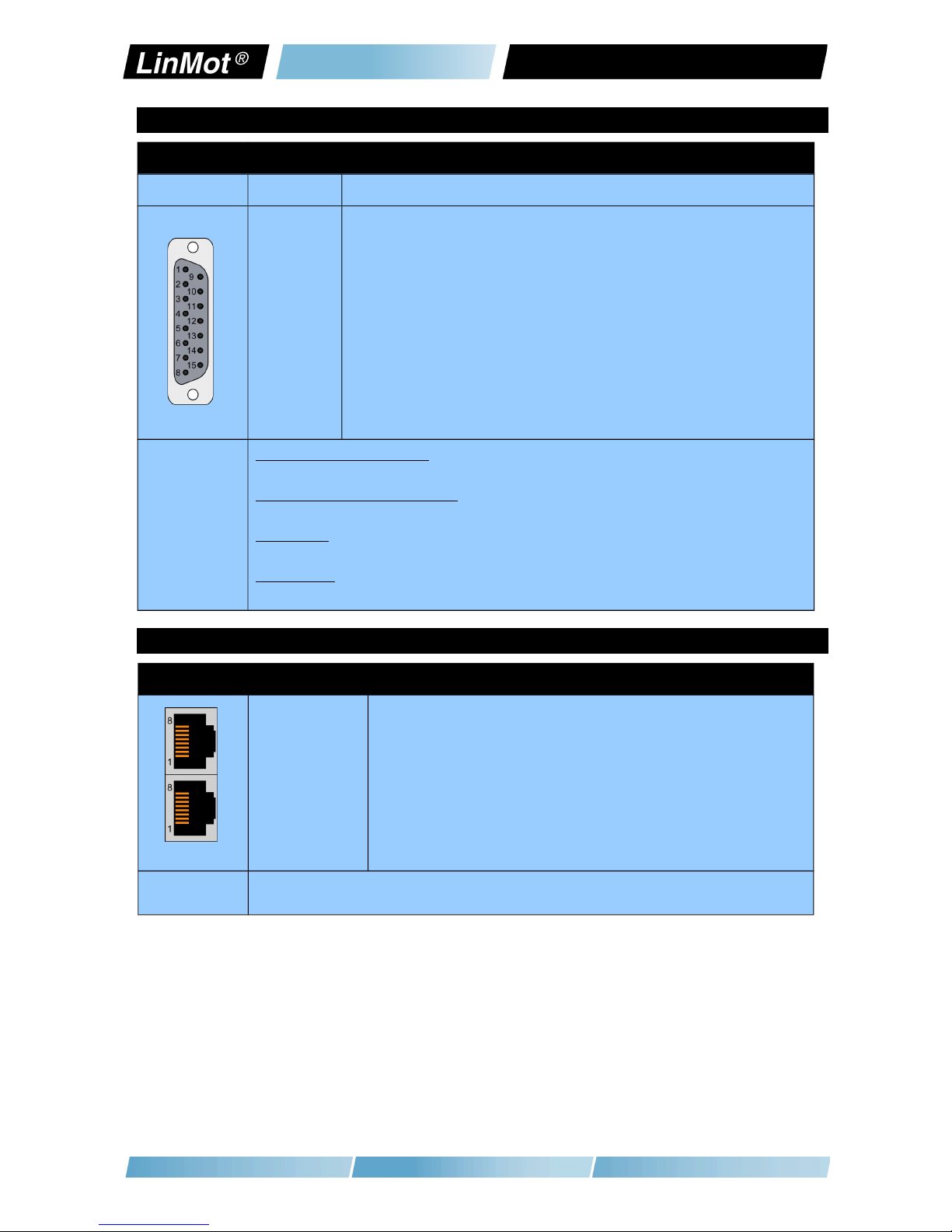
7.3 X3
X3 Motor Sensor
1
2
3
4
5
6
7
8
9
case
LinMot Motor:
Do not connect
Do not connect
+5VDC
Sensor Sine
Temp In
Do not connect
Do not connect
AGND
Sensor Cosine
Shield
DSUB-9 (f) Note:
Use +5V (X3.3) and AGND (X3.8) only for motor internal hall sensor supply (max. 100mA).
Cable length < 30m.
Caution:
Do NOT connect AGND (X3.8) to ground or earth!
NTI AG / LinMot®www.LinMot.com Page 11/22

1200 Installation Guide Preliminary
7.4 X4
X4 Logig Supply / IO Connection
11
10
9
8
7
6
5
4
3
2
1
AnIn- X4.11
AnIn+ X4.10
AnIn X4.9
In X4.8
In X4.7
In X4.6
In X4.5
Out X4.4
Out X4.3
+24VDC Supply
GND Supply
Configurable Analog Input differential (with X4.10)
Configurable Analog Input differential (with X4.11)
Configurable Analog Input single ended
Configurable Input
Configurable Input
Configurable Input
Configurable Input
Configurable Output
Configurable Output
ogic Supply 22-26 VDC
Ground
Spring cage
connector
Inputs (X4.5 .. X4.8): 24V / 5mA ( ow evel: –0.5 to 5VDC, High evel: 15 to 30VDC)
Outputs (X4.3 & X4.4): 24V / max.100mA, Peak 370mA (will shut down if exceeded)
Analog inputs: 12 bit A/D converted.
Supply 24V / type. 500mA / max. 2.5A (if all outputs “on” with max. load.)
- Use 60/75°C copper conductors only
- Conductor cross-section max. 1.5mm2
- Stripping length: 10mm
CAUTION: For continued protection against risk of fire, replace only with same type and rating of fuse.
7.5 X9
X9 PROFIBUS DP (only available on E1230-DP-UC)
1
2
3
4
5
6
7
8
9
case
Not connected
Not connected
RxD/TxD-P
CNTR-P
GND (isolated)
+5V (isolated)
Not connected
RxD/TxD-N
Not connected
Shield
DSUB-9 (f) Max. Baud rate: 12Mbaud
Page 12/22 www.LinMot.com NTI AG / LinMot®
Preliminary 1200 Installation Guide
7.6 X13
X13 External Position Sensor Differential Hall S itches
ABZ with Hall Switches
1
9
2
10
3
11
4
12
5
13
6
14
7
15
8
case
+5V DC
A+
A-
B+
B-
Z+
Z-
Encoder Alarm
GND
U+
U-
V+
V-
W+
W-
Shield
DSUB-15 (f) Position Encoder Inputs ( RS422):
Max. counting frequency: 25 Mcounts/s with quadrature decoding, 40ns edge separation
Differential Hall Switch Inputs (RS422):
Input Frequency: <1kHz
Enc. Alarm In:
5V / 1mA
Sensor Supply:
5VDC max 100mA
7.7 X17 - X18
X17 - X18 RealTime Ethernet 10/100 Mbit/s
X17 RT ETH In
X18 RT ETH Out
Specification depends on RT-Bus Type. Please refer to according documentation.
RJ-45
NTI AG / LinMot®www.LinMot.com Page 13/22

1200 Installation Guide Preliminary
7.8 X19
X19 System
1
2
3
4
5
6
7
8
case
(Do not connect)
(Do not connect)
RS232 Rx
GND
GND
RS232 Tx
(Do not connect)
(Do not connect)
Shield
RJ-45 Use Adapter cable AC01-RJ45/Df-2.5-RS1 (Art.-No. 0150-2143) for Configuration over RS232.
7.9 X33
X33 Safety Relays (only ith the -1S option)
4 / 8
3 / 7
2 / 6
1 / 5
Ksr +
Ksr -
Ksr f+
Ksr f-
Safety Relay 1 / 2 Input positive
Safety Relay 1 / 2 Input negative
Safety Relay 1 / 2 feedback positive
Safety Relay 1 / 2 feedback negative
Spring cage connector - Use 60/75°C copper conductors only
- Conductor cross-section max. 1.5mm2
- Stripping length: 10mm
- Never connect the safety relays to the logic supply of the drive!
7.10 S1 - S2
S1 - S2 Address Selectors
S1 (5..8)
S2 (1..4)
Bus ID High (0 … F). Bit 5 is the SB, bit 8 the MSB.
Bus ID ow (0 … F). Bit 1 is the SB, bit 4 the MSB.
The use of these switches depends on the type of fieldbus which is used. Please see the corresponding
manual for further information.
Page 14/22 www.LinMot.com NTI AG / LinMot®

Preliminary 1200 Installation Guide
7.11 S5
S5 Bootstrap
S5 Bootstrap
7.12 LEDs
LEDs State Display
Green
Yellow
Yellow
Red
24V ogic Supply OK
Motor Enabled / Error Code ow Nibble
Warning / Error Code High Nibble
Error
7.13 RT BUS LEDs
RT Bus LEDs RT Bus State Display
Green
Red
OK
Error
The use of these EDs depends on the type of fieldbus which is used. Please see the corresponding
manual for further information.
NTI AG / LinMot®www.LinMot.com Page 15/22

1200 Installation Guide Preliminary
8 Error Codes
Error Codes
Error Warn EN Description
Off Warning Operation
Enabled
Normal Operation:
Warnings and operation enabled are displayed.
On ● ~2Hz
0..15 x
Error Code
High Nibble
● ~2Hz
0..15 x
Error Code
ow Nibble
Error:
The error code is shown by a blink code with “WARN” and “EN”.
The error byte is divided into low and high nibble (= 4 bit).
”WARN” and “EN” are blinking together.
The error can be acknowledged.
(e.g.: WARN blinks 3x, EN blinks 2x; Error Code = 32h)
● ~2Hz ● ~2Hz
0..15 x
Error Code
High Nibble
● ~2Hz
0..15 x
Error Code
ow Nibble
Fatal Error:
The error code is shown by a blink code with “WARN” and “EN”.
The error byte is divided into low and high nibble.
”WARN” and “EN” are blinking together.
Fatal errors can only be acknowledged by a reset or power cycle.
(e.g.: WARN blinks 3x, EN blinks 2x; Error Code = 32h)
● ~4Hz ● ~2Hz
0..15 x
Error Code
High Nibble
● ~2Hz
0..15 x
Error Code
ow Nibble
System Error:
Please reinstall firmware or contact support.
● ~0.5Hz ● ~0.5Hz On Signal Supply 24V too lo :
The error and warn EDs blink alternating if the signal supply +24V (X4.2) is
less than 18VDC.
The meaning of the error codes can be found in the
Usermanual_MotionCtrl_Software_SG5 and the user manual of the installed
interface software. These documents are provided together with inMot-Talk
configuration software and can be downloaded from www.linmot.com.
Page 16/22 www.LinMot.com NTI AG / LinMot®

Preliminary 1200 Installation Guide
9 Safety Wiring
The C1200 drives with the -1S option have internal safety functions:
Two Safety relays Ksr in series, which support the supply voltage for the motor
drivers. There are also two feedback contacts for each relay.
To enable the -1S drives both relays have to be switched on.
Minimal wiring:
- Connect X33.8 and X33.4 to 24VDC (from safety)
- Connect X33.7 and X33.3 to GND (from safety)
Attention: Never connect X33.8 and X33.4 to the logic supply of X4!
If an overvoltage protection is needed, it must be provided externally and
sized according the safety circuit of the machine!
Attention: The drop out time of the relays is depending on the external circuitry!
Safety Relay Ksr
Nominal voltage 24 VDC
Min. pick-up voltage at 20°C ≤ 16.8V
Drop-out voltage at 20°C ≥ 2.4 V
Drop-out time (no protection circuit) Typ. 3ms
Coil resistance at 20°C 2'100 Ω ± 10%
Type EN 50205, type A
Contact lifetime > 10'000'000
Manufacturer and type Elesta relays / SIS112 24VDC
Drive Classification according EN ISO 13849-1 (safety of machinery) (preliminary)
Category cat = 3
Performance evel P = d
Diagnostic Coverage DC = high
Mean Time to hazardous failure of one channel MTTFd = high
NTI AG / LinMot®www.LinMot.com Page 17/22

1200 Installation Guide Preliminary
10 Physical Dimensions
1200 Series single axis drive C12xx-xx-XC-0S C12xx-xx-XC-1S
Width mm (in) 25.3 (1.0)
Height mm (in) 166 (6.54) 176 (6.93)
Height with fixings mm (in) 206 (8.11) 216 (8.5)
Depth mm (in) 106 (4.17)
Weight g (lb) 630 (1.4) 700 (1.54)
Mounting 2 x M5
Case IP 20
Storage Temperature °C -25…40
Transport Temperature °C -25…70
Operating Temperature °C 0…40 at rated data
40...50 with power derating
Relative humidity 95% (non-condensing)
Pollution IEC/EN
60664-1
Pollution degree 2
Site altitude m amsl to be defined
Shock resistance (16ms) -1S option 3.5g
Vibration resistance (10-200Hz) -1S option 1g
Max. Case Temperature °C 90
Max. Power Dissipation W ???
Mounting place In the control cabinet
Mounting position vertical
Distance between Drives mm (in) Without Power Derating:
20 (0.8) horizontal / 50 (2) vertical
With Power Derating:
5 (0.2) horizontal / 20 (0.8) vertical
Page 18/22 www.LinMot.com NTI AG / LinMot®

Preliminary 1200 Installation Guide
11 Po er Supply Requirements
Motor Po er Supply
The calculation of the needed power for the Motor supply is depending on the
application and the used motor. The nominal supply voltage is 72- 80 VDC. The
possible range is from 24 to 85VDC, for U from 30 to 85 VDC.
ATTENTION:
The motor supply can rise up to 95 VDC when braking.
This means that everything connected to that power supply needs a
voltage rating of 100 VDC. (Additional capacitors, etc...). Due to high
braking voltage and sudden load variations of linear motor
applications,
only specially designed po er supplies can be used.
Signal Po er Supply
The logic supply needs a regulated power supply of a nominal voltage of 24 VDC.
The voltage must be between 22 and 26 VDC.
Current consumption:
min. 0.5A (no load on the outputs)
typ. 1.5A (all 10 outputs “on” with 100mA load and /Break with no load)
max. 2.5A (all 10 outputs “on” with 100mA load and /Break with 1A load)
Do not connect the safety relays to the 24VDC Signal Supply!
Use a separate power supply for the safety circuit!
12 Regeneration of Po er
Connect an additional capacitor to the motor power supply. It is recommended to
use a capacitor >= 10’000 μF
(install capacitor close to the drive supply!)
NTI AG / LinMot®www.LinMot.com Page 19/22

1200 Installation Guide Preliminary
13 Ordering Information
Item Description Art. Nr.
C1200-GP-XC-0S GENERA PURPOSE Drive (72V/25A) 0150-1882
C1230-DP-XC-0S PROFIBUS DP Drive (72V/25A) 0150-2386
C1250-P -XC-0S POWER INK Drive (72V/25A) 0150-1885
C1250-SE-XC-0S SERCOS over ETHERCAT Drive (72V/25A) 0150-1897
C1250-IP-XC-0S ETHERNET IP Drive (72V/25A) 0150-1886
C1250-EC-XC-0S ETHERCAT Drive (72V/25A) 0150-1884
C1250-PN-XC-0S PROFINET Drive (72V/25A) 0150-1888
C1250-SC-XC-0S SERCOS III Drive (72V/25A) 0150-1887
C1200-GP-XC-1S GENERA PURPOSE Drive (72V/25A/STO) 0150-2344
C1230-DP-XC-1S PROFIBUS DP Drive (72V/25A/STO) 0150-2387
C1250-P -XC-1S POWER INK Drive (72V/25A/STO) 0150-2347
C1250-SE-XC-1S SERCOS over ETHERCAT Drive (72V/25A/STO) 0150-2350
C1250-IP-XC-1S ETHERNET IP Drive (72V/25A/STO) 0150-2346
C1250-EC-XC-1S ETHERCAT Drive (72V/25A/STO) 0150-2345
C1250-PN-XC-1S PROFINET Drive (72V/25A/STO) 0150-2348
C1250-SC-XC-1S SERCOS III Drive (72V/25A/STO) 0150-2349
RS232 PC config. Cable 2.5m For E1200 / E1400 0150-2143
ATTENTION: The connectors have to be ordered separately and are not
included ith the drive!
14 International Certifications
Certifications
Europe See chapter “15 Declaration of Conformity CE-Marking“
UR U 508C recognition pending
Page 20/22 www.LinMot.com NTI AG / LinMot®
Other manuals for C1200
1
Table of contents
Other LinMot Amplifier manuals


