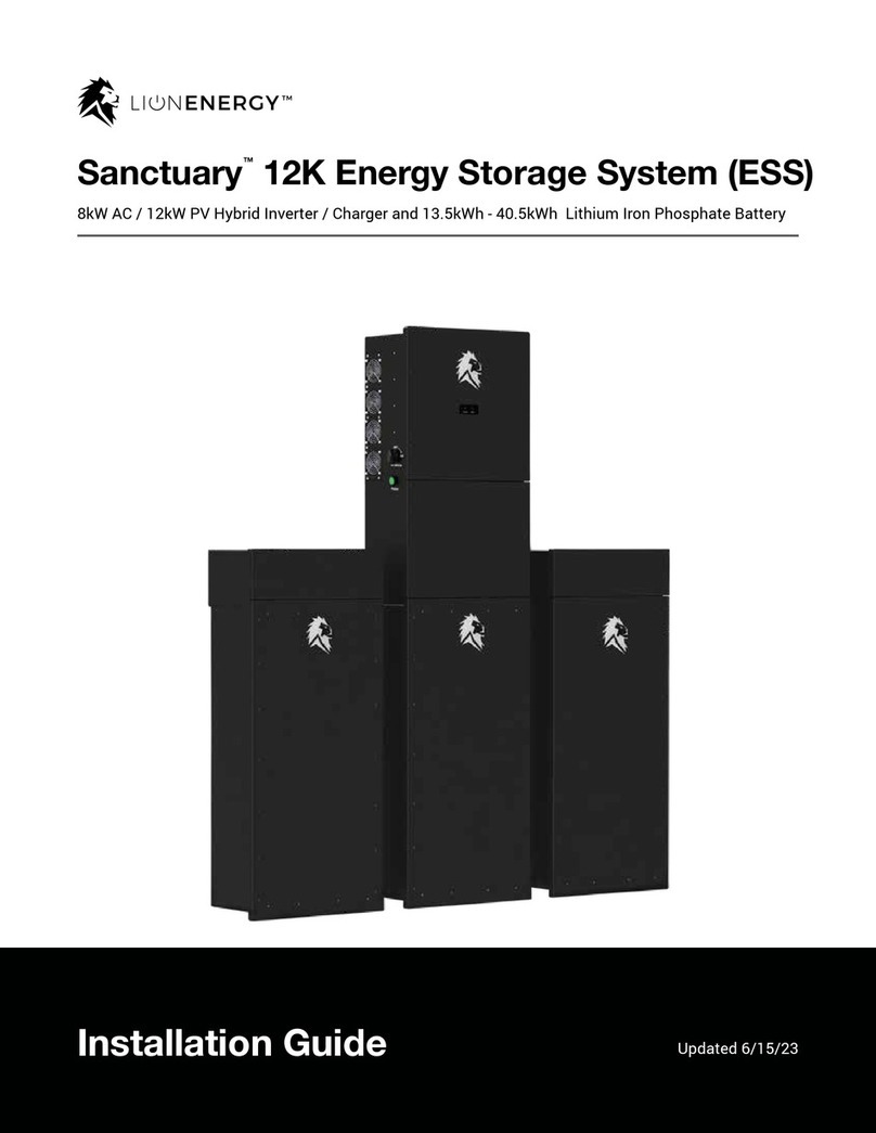
Lion Energy Sanctuary 8kW User manual

Sanctuary™Energy
Storage System
User Manual
8kW Hybrid Inverter / Charger & 13.5kWh Lithium Battery

2
USER GUIDE
This unit provides safe, silent, and renewable electric power. It is very important to carefully read this
user manual before using the product. Keep this manual for future reference. It can also be found at
www.lionenergy.com.
Carefully read and strictly comply with all safety directives. Otherwise, personal bodily injury or death
may result.
Follow these directives for safe use:
• Caution: Only qualied personnel/technicians can install and service this device with or without a
battery. Never charge a frozen battery.
• Before using the inverter, read the instructions and warning signs for the Lithium battery and all
relevant sections in the instruction manual.
• Do not disassemble the inverter. If you need maintenance or repair, take it to a professional
service center. Improper reassembly may result in electric shock or re and will void the warranty.
• To reduce risk of electric shock, disconnect all wires before performing maintenance or cleaning.
Turning off the unit alone does not reduce this risk.
• For optimum performance of the inverter, follow the specications when selecting the appropriate
cable size. It is very important to correctly operate the inverter.
• Be very cautious when using metal tools near the battery. Dropping a tool on or in the unit may
cause a spark or short circuit in the battery or other electrical parts, and may even cause an
explosion.
• Strictly follow the installation procedure when disconnecting the AC or DC terminals. Refer to the
Installation section of this manual for details.
• Grounding instructions: Connect the inverter to a permanent, grounded wiring system. Be sure to
comply with local requirements and regulations when installing the inverter.
• Never cause AC output and DC input to become short circuited. Do not connect to the mains when
there is a short circuit in the DC input.
READ THIS MANUAL IN ITS ENTIRETY
BEFORE OPERATING THE UNIT.

3
USER GUIDE
Table of Contents
04 Part Identication
05 Product Introduction
05 Product Features
05 Basic System Architecture
06 Installation
14 Operation
23 Fault Information and Processing
25 Technical Specications
28 Warranty

4
USER GUIDE
Part Identication
The Lion Sanctuary is a powerful solar inverter/charger and energy storage system. It is used to
harness the energy of the sun to provide power for your home, cabin, or houseboat. The diagram below
identies the parts for the inverter/charger components on the unit.
# #
1. 6.
2. 7.
3. 8.
4. 9.
5.
Part Part
High Voltage DC Disconnect PV Input with MPPT Connectors
On/Off Button Wi-Fi Adapter
Status Indicator Lights (Normal/Alarm) Earth Ground
Battery Input Connectors Grid, Generator and Load AC Input/Output
Communication Ports

5
USER GUIDE
Product Introduction
This is a multi-functional inverter, which combines the functions of an inverter, solar charger, and
battery charger to offer uninterruptible power supply. The Lion Sanctuary is operated with an app from
your smart device or computer. The app allows for customized settings and provides necessary data.
Product Features
The Sanctuary 8kW inverter offers an impressive array of features:
• 240V split-phase pure sine wave inverter, 208V three-phase pure sine wave inverter.
• Self-consumption mode and grid-tied net metering capable.
• Programmable supply priority for either the battery or the grid.
• Programmable multiple operation modes: On grid, Off grid, and UPS (Uninterrupted Power Supply
at 5 ms).
• Congurable battery charging current / voltage.
• Congurable AC / Solar charging priority.
• Compatible with main power or generator power.
• Overload, excessive temperature, and short circuit protection.
• Smart battery charger design for optimized battery performance.
• Prevents excessive power overow to the grid.
• Wi-Fi monitoring with two built-in sets of MPPT chargers (Maximum Power Point Tracker).
• Maximum 160A battery discharge, 7.6kW charging capacity.
• Customizable power output settings to account for time of use rate structures to maximize ROI.
Basic System Architecture
The gure on pg. 6 depicts the basic application of the Lion Sanctuary System. It requires a generator or
utility, solar panels and energy storage (Lithium battery) to have a complete running system.
The Lion Sanctuary System can provide power for residences, including appliances, communication
equipment, lights and other devices.
Consult with Lion Energy integrator for other possible system architectures to
accommodate your specic requirements.
Other architectures

6
USER GUIDE
Installation
Count Count
1 1
2 1
3
6
2
1
4
7
6
1
5
8
1
2
Part
Sanctuary 8kW Inverter / Charger
13.5kWh Lithium Battery
Stainless Steel Mounting Screws M4*12
This Manual
Stainless Steel Expansion Bolts M6*80
Wi-Fi Adapter
DC Fuse
Current Transformer (or use with optional anti-backow function)
Parts List

7
USER GUIDE
Installation Location
Before installing the Lion Sanctuary System (inverter/charger and battery), consider the following when
choosing a location for installation:
• Install the Sanctuary System in a climate controlled location, regulated temperature between 32º
to 86º F. The Sanctuary System is suitable for use in residential dwelling units where permitted.
This equipment meets the cell level performance criteria of UL 9540A.
• Be sure to keep other objects and surfaces away from the unit to permit adequate heat dissipation
and provide space for wiring access. For proper air circulation, provide a clearance of at least 20
inches to the side and at least 12 inches above the unit.
• Hardware not included (fasteners for specic wall mount). Installer may need to purchase
hardware for their specic mounting needs.
Brackets for Inverter Mounts
Brackets for Battery Mounts

8
USER GUIDE
A maximum of 36 panels can be connected.
They must be connected properly as
indicated below. To achieve proper
conguration with solar panels, loads must
be equalized between MPPTs and their
inputs. Each MPPT has two sets of inputs
that must be balanced as shown in the table
to the right.
Battery Connection
Before connecting any wires, remove the
metal cover by removing four screws as
shown in the gure below.
# of Panels
5
6
7
8
9
10
11
12
13
14
15
16
17
18
19
20
21
22
23
24
25
26
28
30
32
34
36
PV 1- A
5
6
7
8
9
5
6
6
7
7
8
8
6
6
6
7
7
7
8
8
8
7
7
8
8
9
9
PV 1 - B
-
-
-
-
-
5
-
6
-
7
-
8
6
6
6
7
7
7
8
8
8
7
7
8
8
9
9
PV 2 - A
-
-
-
-
-
-
5
-
6
-
7
-
5
6
7
6
7
8
7
8
9
6
7
7
8
8
9
PV 2 - B
-
-
-
-
-
-
-
-
-
-
-
-
-
-
-
-
-
-
-
-
-
6
7
7
8
8
9

9
USER GUIDE
Model Wire Size Torque Value
8kW 2AWG 17.7 in-lbs
Follow the steps below to connect the battery:
1. Choose a suitable battery cable connector which can t into the battery terminals.
2. Use a suitable screwdriver to unscrew the bolts and insert the battery connectors, then fasten the
bolt with the screwdriver. Be sure to tighten the bolts clockwise with a torque of 17.7 in-lbs.
3. Ensure that the polarity at both the battery and the inverter is correct.
4. Thread the wire through the weather resistant cable gland. Secure the wire connection, and attach
the wires to the strain relief device with cable ties.
All wiring must be performed by a professional electrician.
There will be high voltage in the unit; perform the installation with care.
Professional wiring installation
High voltage
Connecting the battery with a suitable cable is important for ecient operation of the
system.
Before making the nal DC connection or closing the DC breaker / disconnect, be sure the
positive (+) connects to positive (+) and negative (-) connects to negative (-).
Suitable battery cable (included)
Correctly connect positive and negative

10
USER GUIDE
Input / Output Connection
Before connecting to AC input power source, install a separate AC breaker (80A or less) between the
inverter and the AC input power source. This will ensure that the inverter is a safe 90A pass-through. It
also ensures that the inverter will readily disconnect during maintenance.
Observe that there are three terminal blocks with IN and OUT markings.
Model Wire Size Torque Value
8kW 6AWG 10.6 in-lbs
For system safety and ecient operation, it is very important to use an appropriate cable
for the AC input connection. To reduce risk of injury, use the correct cable according to the
information in the table below.
Use the correct cable
Be sure to disconnect all power sources before attempting to wire the unit.
If a power shortage occurs and recovers in a short time, it may cause damage to the
appliances you connect to the inverter. Appliances such as an air conditioner will need
at least 2-3 minutes to restart because there must be sucient time to balance the
refrigerant gas in the system. To prevent such damage, check the air conditioner manual
to learn if it is equipped with time-delay function. If not, this inverter may trigger an
overload fault and terminate all output to protect your appliance. However, this may still
cause internal damage to the air conditioner.
Disconnect the power source
Potential damage to appliances

11
USER GUIDE
Refer to the gures below and follow these steps to connect the AC input and output:
1. Before connecting the AC input and output, be sure to to rst disconnect all power sources,
including the DC disconnect.
2. Remove a 0.4” length of insulation sleeve, unscrew the bolts, and insert the AC input wires through
the cable glands according to the polarities indicated on the terminal block. Then tighten the
terminal screws. Ensure that the connection is complete.
3. Insert the AC output wires through the cable glands according to the polarities indicated on the
terminal block, then tighten the terminal screws. Be sure to connect the corresponding N wires
and PE (Ground) wires to related terminals. Make sure all connections are tightened to 10.6 in-lbs.
L1 L2 N Wiring AC Terminals
Weather Resistant Cable GlandsTerminal Block

12
USER GUIDE
PV Connection
Before connecting the unit to the PV modules, install a separate DC circuit breaker between the inverter
and PV modules. It is very important for system safety and ecient operation to use the appropriate
cables for the PV module connections. To reduce risk of injury, use the recommended cable size given
in the table below.
Model Wire Size Torque Value
8kW 1x12AWG 10.6 in-lbs
Use a PV junction box that provides surge protection. Otherwise, damage from a lightning
strike to a PV module may result in damage to the inverter.
Use surge protection
To avoid any malfunction, do not connect any PV modules with possible current leakage
to the inverter. For example, grounded PV modules will cause current leakage to the
inverter. When using PV modules, be sure there is no negative grounding.
Avoid PV modules with current leakage
Solar Input Wiring

13
USER GUIDE
Follow the steps below to connect the PV module:
1. Remove 0.4” of the insulation sleeve for positive and negative conductors.
2. Use a crimping tool to place bootlace ferrules on the ends of both the positive and negative wires.
3. Verify correct polarity of all wire connections for the PV modules and PV input connectors. Insert
the wires through the cable glands and connect the positive pole (+) of the connection wire to the
positive pole (+) of the PV input connector. Connect the negative pole (-) of the connection wire to
the negative pole (-) of the PV input connector. Close the switch and ensure the wires are secure.
Inverter Model Sanctuary 8kW
Maximum PV Array Open Circuit Voltage
PV Arrray MPPT Voltage Range
500 VDC
125 - 425 VDC
PV Module Selection
PV Module Wire Connection
When selecting suitable PV modules, be sure to consider the following (see table below):

14
USER GUIDE
Operation
Download the Solarman™ app for iPhone, Android or computer. Turn on the Sanctuary System by
pressing the ON/OFF button on the side.
NOTE: Solarman™ Pro App is required for installation and can be used for monitoring.
Solarman™ 2.0 App is for monitoring only.
Select local mode in the app and scan the QR code on the Wi-Fi adapter.
NOTE: “Local Mode” icon is the blue icon at the bottom right side.
Power ON / OFF
Local Mode
Local Mode App

15
USER GUIDE
Align the QR code on the Wi-Fi Adapter inside
the local mode window (right pic) to scan
theserial number of the Wi-Fi Adapter, then
press next.
Go to Wi-Fi settings and select the access
point with the Wi-Fi adapter serial number
(right pic), then enter the password on the
QR code sticker on the Wi-Fi adapter (shown
above).
Local Mode / QR Scan
Password
QR Scan
Wi-Fi Adapter Serial Number

16
USER GUIDE
Solar Data Screen
Realtime monitoring screen to see what is
going on with the solar and get feedback for
the day’s production.
Go back to the Solarman™ App local mode and proceed to program the inverter and to see the data.
This allows you to ensure the system is set up correctly and to customize settings.
1. There are 6 Realtime data analytic screens to aid in validating the system is working: Solar, Bat-
tery, Grid, UPSload, Inverter and Alerts (defaults to Realtime data/Solar)
2. There are 6 Setting screens to customize your settings depending on how you want to use the
stored energy:
Below are pictures of each of the 6 Realtime and 6 Setting screens.
Realtime Data Screens
Local Mode
Solar Instantaneous Power
MPPT Solar Input Voltage
MPPT Solar Input Current
Daily Solar Energy Production
Total Ongoing Solar
Energy Production
• Battery Setting
• System Work Mode
• Grid Setting
• Smart Load
• Basic Setting
• Advanced Function

17
USER GUIDE
Battery Data Screen
Grid Data Screen

18
USER GUIDE
Inverter Data Screen
UPS Load Data Screen
This is the Inverter data screen that provides
Realtime Data and allows for customization
of Settings.

19
USER GUIDE
Realtime Data Alert Tab
Battery Setting Tab
Warnings and errors will appear under the
“Alert” tab.
The Lion Sanctuary Energy Storage (13.5kWh
battery) has communication capability with
the inverterand it will self-congure the
inverter as shown in this image.

20
USER GUIDE
System Work Mode
System Work Mode settings are
customizable during install so you can
optimize based on how you want your battery
used to offset power consumption.
System Working Mode: Denes how the
inverter offsets power usage.
• Grid Sell: Allow the inverter to sell excess
power to the utility grid under the premise
that the battery bank is fully charged (it
depends on the set charge voltage point).
The amount sold to the grid can be set.
• Zero Export to Load: Inverter only outputs
the power required by the loads connected
to the inverter AC output.
• Zero Export to CT: Inverter only outputs
power to cover the loads on the panel to
which the CT censors are connected.
Solar Sell: Determines if the inverter sells
power back to the power company (Power
company net metering agreement required).
Time of Use: Allows you to offset the power
depending on the time of day. Useful if the
power costs differ depending on the time of
day it is used.
Max Sell Power: Allows you to limit the max
power the Inverter will output.
Energy Pattern: Allows you to direct the
power from solar to cover your home load
rst or to ll the battery rst.
Zero Export Power: Limits the max power the
inverter will provide to offset your usage from
the grid.
Selling Mode TimeX Grid Charge: Sets the
inverter to charge from the grid at a certain
time of day.
Selling Mode TimeX Gen Charge: Sets the
inverter to activate the generator start and
charges from the generator at a certain time
of day.
This manual suits for next models
3
Table of contents
Other Lion Energy Storage manuals
Popular Storage manuals by other brands

Renkforce
Renkforce 1428144 operating instructions

Eminent
Eminent EM4172 user manual

Sans Digital
Sans Digital Towerraid TR5M6G Quick installation guide

Western Digital
Western Digital WDBAAP0000NBK - TV Live Media Player Quick install guide

Seagate
Seagate Momentus 5400.3 ST9100828SB installation guide

GE
GE D400 Substation Data Manager user manual