Lion Energy SANCTUARY 99990814 User manual
SANCTUARY INSTALLATION GUIDE
1
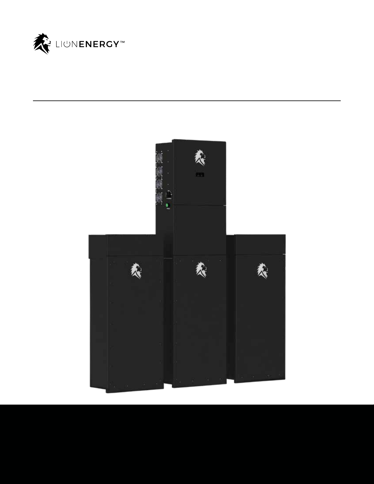
Sanctuary™12K Energy Storage System (ESS)
Installation Guide
8kW AC / 12kW PV Hybrid Inverter / Charger and 13.5kWh - 40.5kWh Lithium Iron Phosphate Battery
Updated 6/15/23

SANCTUARY INSTALLATION GUIDE
2
This unit provides safe, silent, and renewable electric power. It is very important to carefully read this
Installation Guide before using the product. Keep this guide for future reference.
Carefully read and comply with all safety directives. Otherwise, personal bodily injury or death may
result.
Follow these directives for safe use:
• Caution: Only qualied personnel/technicians can install and service this device with or without
a battery.
• Do not turn on the system until nal continuity check is performed.
• Before using the inverter, read the instructions and warning signs for the Lithium battery and all
relevant sections in the manual and commissioning guide.
• Do not disassemble the inverter. If you need maintenance or repair, contact a professional
service center. Improper reassembly may result in electric shock or re and will void the
warranty.
• To reduce risk of electric shock, disconnect all wires before performing maintenance or cleaning.
Turning off the unit alone does not reduce this risk.
• For optimum performance of the inverter, follow the specications when selecting the
appropriate cable size. It is very important to correctly operate the inverter.
• Be cautious when using metal tools near the battery. Dropping a tool on or in the unit may cause
a spark or short circuit in the battery or other electrical parts, and may even cause an explosion.
• Strictly follow the installation procedure when disconnecting the AC or DC terminals. Refer to the
Installation section of this guide for details.
• Grounding instructions: Connect the inverter to a permanent, grounded wiring system. Be sure to
comply with local requirements and regulations when installing the inverter.
• Do not connect to the mains when there is a short circuit in the DC input.
• This system includes heavy equipment. Use lifting assistance during installation.
READ THIS INSTALLATION GUIDE IN ITS
ENTIRETY BEFORE OPERATING THE UNIT.

SANCTUARY INSTALLATION GUIDE
3
Table of Contents
About the Sanctuary ..................................................................4-7
Sanctuary ESS Overview...................................................................................4
• Inverter Overview ..........................................................................................5
• Parts and Components..............................................................................6-7
Installation ................................................................................. 8-11
• Installation Location.....................................................................................8
• Location Preparation ....................................................................................9
• Mounting Brackets ............................................................................... 10-11
Wiring the Sanctuary ........................................................... 12-31
• Low Voltage DC Wiring ......................................................................... 12-15
• High Voltage DC Wiring ........................................................................ 16-17
• Rapid Shutdown..........................................................................................18
• Remote Shutdown Switch..........................................................................19
• AC Wiring .......................................................................................... 20-21
• CT Installation.............................................................................................22
• Generator Wiring................................................................................... 23-24
• Continuity Testing................................................................................. 25-27
• Parallel Inverter Connection.......................................................................28
• Inverter Communication Wiring .................................................................29
• BMS Communication Wiring......................................................................30
• Inverter Wiring Diagram..............................................................................31
Fault Information and Processing ................................ 32-35
Specications ................................................................................36
Warranty Information .................................................................37

SANCTUARY INSTALLATION GUIDE
4
Sanctuary ESS Overview
The Sanctuary is a multi-functional Energy
Storage System (ESS), which incorporates the
functions of an inverter, solar charger, battery
charger, generator (not included), and lithium
iron phosphate battery. The Sanctuary is
commissioned and monitored by way of Lion
App, available on smart phone and PC.
The Sanctuary ESS can be considered your
own personal power plant. Whether you are
covering essential loads or covering an entire
home, the correct sizing of the Sanctuary is
key for the system to function properly. Before
sizing, you must review the Sanctuary technical
specications.
To size the system, consider the loads you would
like the Sanctuary to cover. Typical essential
loads are refrigeration, furnace, lights, Internet,
and garage door.
Solar Power
Generator
Utility Home Appliances
Sanctuary Energy
Storage System
Basic System Architecture
This gure depicts the
basic application of the
Lion Sanctuary System.
Power is fed into the
system from the power
grid, solar power array
or generator to have
a complete running
system.
The Lion Sanctuary
Energy Storage
System can provide
power for residences,
including appliances,
communication
equipment, lights and
other devices.
Review your existing load center and identify
the breaker size for each of the loads you would
like to cover. Note - any load larger than a 30
amp breaker will require multiple inverters to
cover. Using the code compliant load calculation
method for your jurisdiction, determine the
number of continuous amps required to cover
the desired loads. Each Sanctuary system can
provide for 33.3AAC off-grid (stand alone),
anything more than this will require additional
Sanctuary system(s) to be placed in parallel
(please contact Lion Energy for more details).
Note that the Sanctuary is only sold with both
the inverter and battery as a system, as both are
required for full functionality of the unit. If paired
with solar, we recommend a minimum of 3kW
of PV input per 13.5kWh (per battery of energy
storage).
Essential loads panel
or main panel with
multiple inverters.
SANCTUARY INSTALLATION GUIDE
5
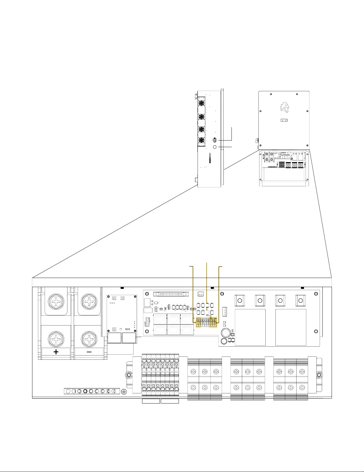
Inverter Overview
High
Voltage DC
Switch
Power
Comm
Port A Comm
Port B
BMS
Coms CT 2 CT 1
Invert
Coms
WCM
WiFi Control
Module
Ether
Coms
GENERATOR GRID INPUT LOAD OUTPUT
L1 L2 N
1 2 3 4
PV+ PV- L1 L2 N L1 L2 N
1 2 3 4
Ground Bar
Low Voltage DC
Remote
Shutdown Switch
Connection
Gen Signal
Start
12V DC Power Supply
location for Rapid
Shutdown
SANCTUARY INSTALLATION GUIDE
6
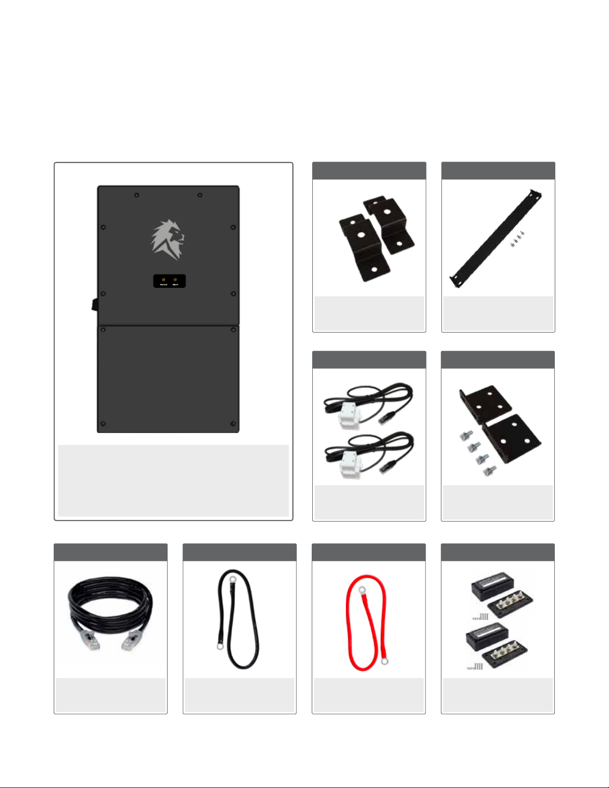
Inverter Parts and Components
12K Inverter
(#50170168)
Solar Power
Generator
Utility Home Appliances
Sanctuary Energy
Storage System
Cat5 Cable (10’)
(#90000136)
2 Per Inverter
CT Pair
1 Per Inverter
Inverter Standoff
Bracket Set
1 Per Inverter
AWG@ Black Eylet-Eyelet
Cable (24”)
(#90000516)
1 Per Inverter
AWG@ Red Eylet-Eyelet
Cable (24”)
(#90000517)
1 Per Inverter
Inverter
Wall Mount
1 Per Inverter
Inverter Wall mount
Bracket Set
(#50170168)
1 Per Inverter
Busbar Set
(#90000508)
1 Per Inverter
SANCTUARY INSTALLATION GUIDE
7
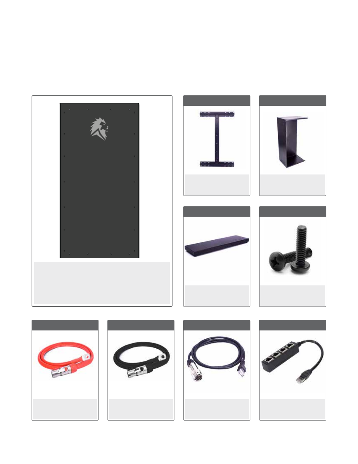
Battery Parts and Components
13.5kWh Battery
(#50170132)
Solar Power
Generator
Utility Home Appliances
Sanctuary Energy
Storage System
Wire Box Cover
(#90000506)
Wire Box Housing Bolts
(#90000518)
Battery Bracket
1 Per Battery
Freestanding Wire Box
(#90000504)
1 Per Battery
AWG2 Battery
Cable Red (55”)
(#90000501)
1 Per Battery
AWG2 Battery
Cable Black (55”)
(#90000500)
1 Per Battery
Battery COM Cable
(#90000508)
1 Per Battery
RJ45 4-Port Splitter
(#90000509)
1 Per Battery
1 Per Battery 4 Per Battery
SANCTUARY INSTALLATION GUIDE
8
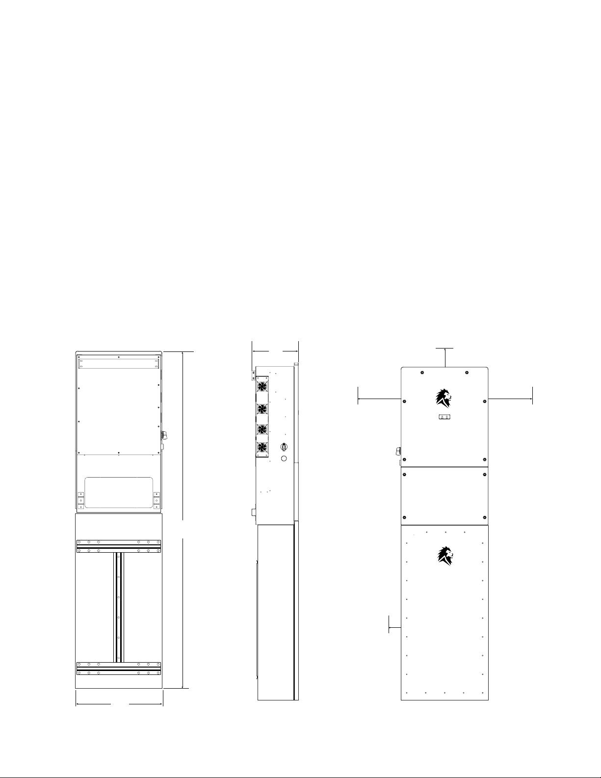
Installation Location
Before installing the Lion Sanctuary System (inverter/charger and battery), consider the following
when choosing a location for installation:
• Install the Sanctuary System in a climate controlled location, regulated temperature between 32º
to 86º F. The Sanctuary ESS cannot be installed in a living space. In other words, the Sanctuary
ESS needs to be installed in a garage or utility/storage room, not your family room.
• Be sure to keep other objects and surfaces away from the unit to permit adequate heat
dissipation and provide space for wiring access. For proper air circulation, provide a clearance of
at least 20 inches to the side and at least 12 inches above the inverter (Battery only requires 0.5”
clearance between batteries).
• To reduce installation costs, it is recommended to install the Sanctuary near existing electrical
panels when possible.
• Note that the inverter, fans, and other internal components emit sound at 60dB (slightly louder
than a standard computer fan).
20”20”
12”
10”
70 ⅝”
18 ½”
½”
Spacing
Between
Batteries
20”20”
12”
10”
70 ⅝”
18 ½”
½”
Spacing
Between
Batteries
20”20”
12”
10”
70 ⅝”
18 ½”
½”
Spacing
Between
Batteries

SANCTUARY INSTALLATION GUIDE
9
Location Preparation:
The Lion Sanctuary ESS battery is designed to be mounted on a wall using a French Cleat system, the
inverter is designed to be mounted to the top of the battery and directly to the wall. It is recommended
that you install a suitable material such as plywood onto an existing wall for anchoring. Before
mounting the brackets ensure the plywood itself is square and level.
After the plywood sheet has been rmly anchored to the wall, the next step will be to install the
mounting brackets.

SANCTUARY INSTALLATION GUIDE
10
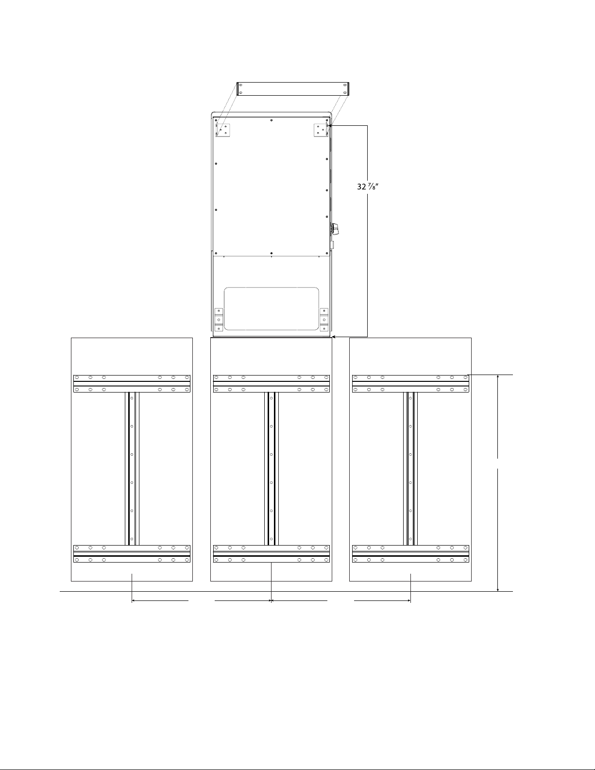
Mounting Brackets
Step 1: Mount Inverter standoff
brackets and Inverter wall mount
brackets to the back of the inverter.
Step 2: Measure a minimum of
30½” from the oor to the top of
the battery bracket and secure the
battery bracket to the wall.
Step 3: Mount battery on the battery
bracket.
Step 4: Measure 32 7/8” from the
top of the battery to the top of the
inverter wall-mount bracket. Mark
placement and secure inverter wall
mount.
Step 5: Mount inverter
Additional batteries should be
mounted at the same height as
mounted in step 1 and 2.
If mounting multiple inverters
follow the spacing guidelines
as previously mentioned
To provide proper airow you must space the inverters 20” from each other.
Multiple Inverter Setup
Floor
Inverter Wall Mount
Battery
Bracket
Inverter Standoff Brackets
Inverter Wall Mount
Brackets
SANCTUARY INSTALLATION GUIDE
11
Minimum battery spacing allowable is 0.5 inches as stated on UL Certicate.
32 ⅞”
30 ½”
Floor
22 ½”22 ½”
Optional Battery Optional Battery
(Yields a recommended 4”spacing between batteries for ease of installation)
Floor

SANCTUARY INSTALLATION GUIDE
12
Low Voltage DC Wiring: 1 Inverter
When wiring 1 inverter to 1 battery,
rst check the voltage of the Battery. It should be
between 45-55.6VDC. If it is not, contact LionESS
support at (435) 244-3352.
Connect the battery cables to the inverter rst. Now
connect the cables to the battery receptacles last.
Next, connect the BMS communication cable to the
port labeled RJ45 on the inverter and then connect
the 4-pin aviation connector to the battery.
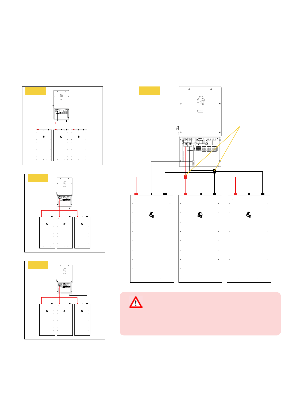
When wiring 1 inverter to multiple batteries,
Step 1: Connect the provided eyelet to eyelet battery
cables to the inverter rst, then to the provided
busbars.
Step 2: Using the provided battery cables, connect
all negative cables from the negative busbar to the
negative battery receptacles,
Step 3: Now connect the positive cables from the
positive busbar to the positive battery receptacles.
Step 4: Next, connect the provided BMS
communication cable splitter to the RJ45 port
labeled BMS Coms on the inverter. Connect each
battery BMS communication cable to each 4-pin
aviation connector on each battery.
+
+ + ++ +
SANCTUARY INSTALLATION GUIDE
13
++ +
++ +
Busbars
++ +
++ +
++ +
Step 1
Step 2
Step 3
Step 4
When connecting multiple batteries, check
voltage on each battery rst. Batteries must be
within 0.5V in order to connect in parallel.
Battery Voltage

SANCTUARY INSTALLATION GUIDE
14
Step 1: Mount busbars directly below each inverter. Connect
busbars to each other. Recommended to add 225A T-Fuse
to positive cable between busbars. (cables and T-Fuses not
provided).
Step 2: Using the provided eyelet to eyelet cables connect
each inverter to their corresponding busbar.
Step 3: Connect the negative (-) battery cables to the battery
receptacles.
Step 4: Connect the positive (+) battery cables to the battery
receptacles last.
Step 5: Connect the BMS Com Splitter to the bottom left RJ45
port labeled BMS Coms on the Parent Inverter. Next, connect
each battery BMS Coms cable to the BMS Com Splitter. Lastly,
connect the 4-pin Aviation end to each battery.
Low Voltage DC Wiring: Multiple Inverter
(3 Inverters, 6 Batteries)
When connecting multiple
batteries, check voltage on each
battery rst. Batteries must be
within 0.5V in order to connect
in parallel.
When connecting busbars
battery cables must be the
same length throughout the
entire system and have a
correct degree and voltage
rating.
Battery Voltage
Step 2
Step 1
+ + + ++
225A
+
225A
+ + + ++
225A
+
225A
For more detailed instructions on connecting the communication cables between
batteries see page 30-31

SANCTUARY INSTALLATION GUIDE
15
+ + + ++
225A
+
225A
Step 3
Step 4
+ + + ++
225A
+
225A
+ + + ++
225A
+
225A
Step 5

SANCTUARY INSTALLATION GUIDE
16
Comm
Port A Comm
Port B
BMS
Coms CT 2 CT 1
Invert
Coms
WCM
WiFi Board
Ether
Coms
GENERATOR GRID INPUT LOAD OUTPUT
L1 L2 N
1 2 3 4
PV+ PV-
L1 L2 N L1 L2 N
1 2 3 4
Ground Bar
Low Voltage DC
String
PV 1
String
PV 2
String
PV 3
String
PV 4
Min
150 VDC
Max
500 VOC
3kW PV
Min
150 VDC
Max
500 VOC
3kW PV
Min
150 VDC
Max
500 VOC
3kW PV
Min
150 VDC
Max
500 VOC
3kW PV
12V DC Power Supply
location for Rapid
Shutdown
High Voltage DC Wiring
The Sanctuary Inverter has 4 MPPT’s that are capable of 3kW of solar each, for a total of 12kW’s. The
minimum allowable voltage is 150VDC. The maximum allowable voltage is 500VOC. The max PV ISC
is 13ADC per MPPT. When conguring your PV strings, you must account for the panel wattage rating
and voltage. Refer to the Sanctuary technical specications for further detail.
All wiring must be performed by a licensed electrician.
Professional wiring installation
There will be high voltage in the unit so be careful while installing the system.
High voltage
Before making the nal DC connection or turning on the high-voltage DC switch /
disconnect, be sure the positive (+) connects to positive (+) and negative (-) connects to
negative (-).
Correctly connect positive and negative
SANCTUARY INSTALLATION GUIDE
17
PV Connection
It is important for system safety and ecient operation to use the appropriate cables for the PV
module connections. To reduce risk of injury, use the recommended cable size given in the table
below. The Sanctuary system accepts up to 10 AWG wire for PV connection.
Use a PV junction box that provides surge protection. Otherwise, damage from a
lightning strike to a PV module may result in damage to the inverter.
Use surge protection
To avoid any malfunction, do not connect any PV modules with possible current leakage
to the inverter. For example, grounded PV modules will cause current leakage to the
inverter. When using PV modules, be sure there is no negative grounding.
Avoid PV modules with current leakage
Verify correct polarity of all wire connections for the PV modules and PV input connectors. Insert the
wires and connect the positive pole (+) of the connection wire to the positive pole (+) of the PV input
connector. Connect the negative pole (-) of the connection wire to the negative pole (-) of the PV input
connector.
PV Module Wire Connection

SANCTUARY INSTALLATION GUIDE
18
Z7 Z6 Z8 Z14 Z10 Z12 Z16 Z13
DRYI_1B
DRYI_1
DRYO_2C
DRYO_2B
DRYO_2A
DRYO_1C
DRYO_1B
DRYO_1A
+12V_COM
GND_COM
Rapid Shutdown
The Sanctuary inverter has a built in 12 Volt DC power supply
for a rapid shutdown (RS) transmitter. The RS ransmitter is
polarity sensitive.
The 12 Volt supply is located as highlighted below:
SANCTUARY INSTALLATION GUIDE
19
Z7 Z6 Z8 Z14 Z10 Z12 Z16 Z13
DRYI_1B
DRYI_1
DRYO_2C
DRYO_2B
DRYO_2A
DRYO_1C
DRYO_1B
DRYO_1A
+12V_COM
GND_COM
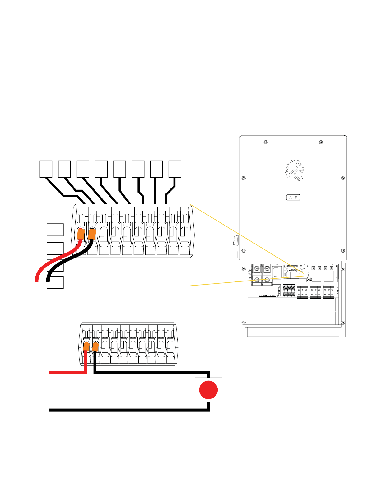
Remote Shutdown Switch
If you are installing a remote shutdown switch, remove the black wire on the 12 volt circuit board on
the inverter. Next, mate this wire and run one wire out to the remote shutdown switch. Then on the
other side of the switch, run one wire back and connect it into the contact where the black wire used
to be on the circuit board.
Remote
Shutdown
Switch

SANCTUARY INSTALLATION GUIDE
20
AC Wiring: 1 Inverter
For grid-tied installation, the Sanctuary is capable of up to a 90 Amp grid-supplied pass-through. The
grid input power must come from an appropriately sized circuit breaker. The maximum wire size the
inverter terminals can accept is 2 AWG copper.
Inverter to cover Essential Loads
Install two breakers into the Main Panel.
One breaker will be the grid input for the Sanctuary Inverter. The load output of the Sanctuary Inverter
will go to a 3-position manual transfer switch. The next breaker will go from the Main Panel directly to
the 3-position manual transfer switch. From the manual transfer switch, lines will go directly into the
Essential Loads Panel.
** Take note: A 3-position manual transfer switch is recommended but not required **
+
Essential Load Panel
Manual Transfer
Switch
Grid Input
Load Output
Grid Input
Main Panel
It is of vital importance that the grid input and load output phases on multiple breakers
match. Crossing phases WILL cause a catastrophic failure on the equipment See
continuity testing on page 27
L1 L2 PHASING
Not provided
by Lion
Energy
This manual suits for next models
2
Table of contents
Other Lion Energy Storage manuals


