Installation
Location
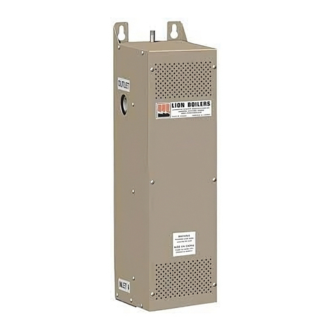
(1) The site selected for installation of your boiler should lea e at least 24” of clear space in
front of the unit. The sides require only enough room for plumbing and electrical
connections (see Fig. 2). The rear of the unit is considered as a “Zero Clearance” face
(see Fig. 2). If wall mounting is chosen ensure that the wall can withstand the weight of
the unit including water (approximately 115 lbs.). Two brackets are pro ided on top and
are drilled for 3/8” bolts or screws, these are for wall mounting. Optional “Mounting
Feet” are a ailable for oor mounting. Holes are also pro ided in these feet for oor
mounting.
(1) To install the optional feet, the two outside #10 screws at the bottom on each side are
remo ed. Each of the feet are then lined up with the holes, then the screws are
tightened back in place holding the feet in place.
(2) The space selected should be well entilated and kept normally below 77º F or 25º C. It
must be clean, and dry. The boiler must not be subjected to water leakage, drips,
splashes, or spray. Flammable materials must not be used or stored anywhere near the
boiler.
(3) Though the unit is suitable for oor or wall mount, only faces indicated as “Zero
Clearance” may be mounted against combustible surfaces.
(4) Units must be mounted straight as shown in Fig. 2 with the outlet at the top, and the
inlet on the bottom. See “Up Arrow” on label on side of boiler.
(5) The circulation pump should be connected to the outlet side of the boiler (see Fig. 3).
Mechanical Installation
(1) Refer to Fig. 3 for a typical system before installation.
(2) Packed with your boiler are the following.
a) Temperature & Pressure Gauge
b) Pressure Relief Val e
c) Air Vent
d) Outdoor Temperature Sensor
e) Necessary ttings.
(3) Mount unit as per instructions under “Location”
(4) Install Pressure Relief Val e and Pressure & Temperature Gauge. These must be
connected directly to the boiler as shown in Fig. 1
(5) A discharge line must be attached to the outlet of the pressure relief al e. The
discharge line will direct water or steam from the pressure relief al e should it open.
The discharge line must be as short as possible, not ha e any al es or restrictions, not
be smaller than the outlet of the pressure relief al e, slope downwards, and the end
must be open to the atmosphere. The discharge line should terminate at a drain 6 inches
abo e the oor le el.
(6) Install inlet and outlet piping.
7


